

Page 1
DUDLEY
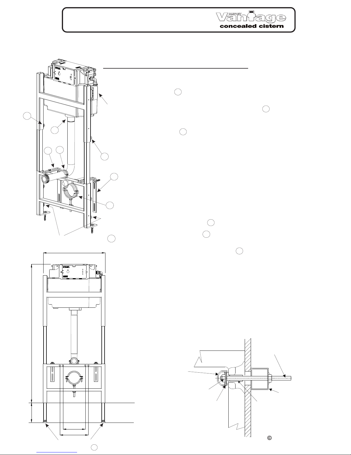
ILLUSION A WITH
Specifically designed for wall hung pans, can be sited on a flat wall, in a
corner or used within furniture.
INSTALLATION INSTRUCTIONS
230mm
180mm
820 - 1120mm
0 - 150mm
498mm
FLOOR LEVEL
FIXING LEVEL
Foot rotational locking screw
at end of adjustable leg
B
Notes -
- Pan outlet connector and soil pipe seal to be purchased
separately. Required diameter 110mm
Fig 1
PAN PROTECTION
BUSH SUPPORT
M12 FULL NUT,
& FLAT WASHER
DECORATIVE CAP
PAN
FRAME
M12 ALLTHREAD
DISHED WASHER
R325586 (11987 - ISSUE A)
Thomas Dudley Ltd. 2012.
1.
To adjust the height of the frame slacken off the bolts holding the adjustable
legs in frame . Adjust the lower section of the frame so that the WC pan
rim is 400mm above the floor level. Re-tighten the bolts clamping the
frame into position. The feet can be rotated, into any position to suit
installation, by using the screw at the foot of the leg . Adjust the top
section of the frame to the required height and re-tighten the bolts.
2. Fit wall straps to frame.
The wall straps can be adjusted and used in any orientation dependant
on the depth of installation required. Minimum depth is 150mm, maximum
depth is 370mm. Once positioned attach firmly to the frame using the M8
bolts, nuts and washers provided.
3. Fixing to wall and floor.
Attach frame securely to wall and floor using the plugs, washers and hex
head screws provided. See diagrams overleaf for corner fitting. It is the
responsibility of the installer to ensure that these fixings in the wall and floor
are strong enough to adequately support the load which will be applied to
the pan in use. It is recommended that fixings are as close as possible to the
horizontal part of the brackets.
4. Fitting flushpipe.
Cut the vertical section of the pipe to the required length, ensuring the pipe is
cut straight. Push the flushpipe onto the spigot of the Vantage cistern and
secure in place using clamp . Cut the horizontal section of the pipe to the
required length. When installing the frame at its maximum height use the
flushpipe extension piece supplied.
5. Fitting pan connector.
Fit a pan connector or soil pipe to clamp and position to suit the pan being
fitted. When in the correct position, complete plumbing to the soil piping.
6. Fitting Partition.
Fit Partition/Wall/Furniture prior to fitting Pan.
7. Fitting pan.
Ensure M12 allthread protrudes sufficiently for correct and secure installation
of the pan. See fig. 1 for installation detail.
Set frame height .
A
B
C
D
E
F
Clamping bolts at rear of uprights
Vantage
Mounting
Brackets
E
D
C
C
F
A
A
A
Page 2
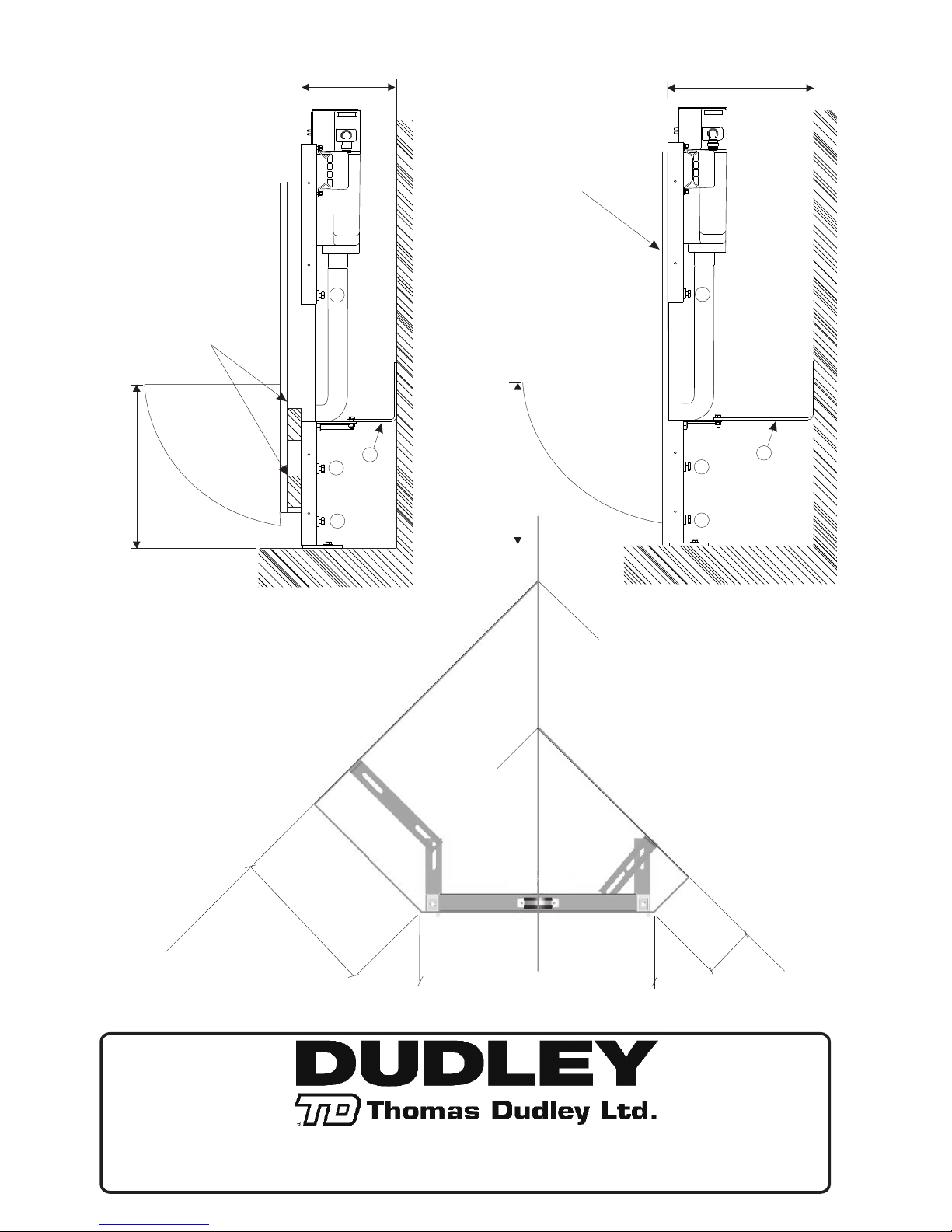
305mm max
500mm
95mm min
Plan view of
Corner Fitting
Note - These diagrams are for
illustrative purposes only. This
product should be fitted in line
with good plumbing and
installation practices.
Dauntless Works, P.O.Box 28, Birmingham New Road, Dudley,
West Midlands, DY1 4SN
Telephone: 0121 530 7000
Fax: 0121 557 5345
E-mail: sales@thomasdudley.co.uk
Built-in System
with dry wall
400 mm
150 - 370 mm
A
A
C
Panel
A
150 - 370 mm
Built-in System
in Furniture
Pan support batten’s
to compensate for
plinth recess
(not supplied)
400 mm
A
A
A
C
 Loading...