

Page 1
user
manual
Page 2

NOTE!
Please read this manual carefully before your first flight
Very important!
Before use it is vital to check in which configuration the steering lines and pulleys
are currently set (lower or upper hangpoints) and adjust them to your preferences if
necessary.
The risers have three points to fix the pulleys on – lengthened upper, lower, and
middle one (see risers on page 35). On each main steering line there are three
points marked, lower, upper and middle one, to fix the steering handle according to
position of the pulley.
Steering lines must not not push down the trailing edge when not operated – this
must be observed in all possible configurations of trimmers and speed-system.
Steering lines must have a couple of centimeters play before they engage affect
the canopy (see section 3.1 on the proper adjustment). For sake of safety it is
always recommended to set the brakes rather too loose than too tight. Make sure
they are set symmetrically, too.
Ill-adjusted steering lines may cause you to misinterpret the canopy’s
behaviour in flight, and in case of encountering turbulence in accelerated
flight dangerous collapses may occur (see page 20).
When flying at full speed (trimmers opened / trimmers opened and speedbar
pushed), especially in uneasy air, it is highly recommended to steer the paraglider
using alternative steering methods like TEA or ALC+ only.
With increasing speed an effect of „inverting” the profile when trailing edge is being
pulled down emerges (pulling the brakes, see page 20). That effect can cause
dynamic collapses, especially at full speed.
The safest way to change your course at high speeds is to use the TEA lines, or (in
the order of safety) the ALC+ handles. Any steering inputs should be smooth and
easy, without sharp and/or deep movements. Such actions can dynamically change
pressure distribution over the airfoil, leading to collapses.
These warnings affect every paraglider and Universal is no exception!
Page 3

TABLE OF CONTENTS
Page
1. Introduction......................................................................................2
2. The wing..............................................................................................3
2.1 Design
2.2 Structure
3. Flight operation............................................................................8
3.1 Steering lines and speed system adjustment
3.2 Free flying
3.2.1 Take-offt
3.2.2 Flight
3.2.3 Landing
3.2.4 Winching
3.3 Powered flights
3.3.1 Take-off
3.3.2 Flight
3.3.3 Landing
3.3.4 Golden rules
3.4 Quick descent methods
3.4.1 Big ears
3.4.2 Spiral dive
3.4.3 B-stall
3.5 Aerobatics
3.5.1 Wing over
3.6 Extreme manoeuvrese
3.6.1 One sided collapse
3.6.2 Frontal collapse
3.6.3 Full stall and negative spin
3.6.4 Deep stall
3.6.5 Line over and cravatte
3.6.6 Emergency steering
4. Paraglider care....................................................................................27
4.1 Packing & Storage
4.2 Cleaning
4.3 Repair
4.4 Deterioration - a few tips
5. Technical data......................................................................................29
6. Warranty, AeroCasco..........................................................................30
7. What have you bought.......................................................................32
8. Rigging tables and scheme ................................................................33
9. Risers - design and accessories ........................................................35
Page 4

1. INTRODUCTION
CONGRATULATIONS
We are pleased to welcome you among the growing number of DUDEK
PARAGLIDERS pilots. You've become a proud owner of recreational stateof-the-art paraglider, built according to recent trends in both free-flying and
paramotor wings.
Extensive development, application of the most modern methods and
thorough testing resulted in a friendly behaving paraglider, offering the pilot a
lot of fun combined with great performance.
We wish you many enjoyable and safe flying hours.
DISCLAIMER
Please read this Manual carefully and note following details:
= The purpose of this Manual is to offer guidelines to the pilot using the
paraglider and it is by no means intended to be used as a training
manual for this or any other paraglider.
= You may only fly a paraglider when qualified to do so or when
undergoing training at an accredited School or with an Instructor.
= Pilots are personally responsible for their own safety and their
paraglider's airworthiness.
= The use of this paraglider is solely at the user's own risk! Neither the
manufacturer nor dealer do accept any liability connected with this
activity.
= This paraglider on delivery meets all the requirements of the EN 926-1
and 926-2 regulations or has an airworthiness certificate issued by the
manufacturer. Any alterations to the paraglider will render its
certificates invalid.
NOTE
Dudek Paragliders warns that due to constant process of development the
actual paraglider may differ slightly from the one described in the manual.
2
Page 5

USER MANUAL
2. THE WING
For whom Universal?
Universal us the first paraglider ever to smoothly and efficiently merge two
aspects:
- nicely hadling free-flying paraglider (with EN/B certificate),
- full-blood paramotor canopy (conforming to DGAC standard).
Universal is dedicated for beginner and recreational pilots who fly:
- exclusively free (but want to benefit from moderate reflex ability)
- mostly free, sometimes with paramotor
- both free and paramotor
- mostly with paramotor, sometimes free
- exclusively paramotor (but appreciate better economy, easier launch and
nicer handling than in standard paramotor wing, like Synthesis2)
Universal is a great free-flying recreational paraglider, including cross-country.
Beginner XC pilots will surely appreciate exceptional comfort in uneasy thermals,
resulting from considerable amount of reflex traits present in the design.
On activating the trimmers and setting up the ALC+ steering, Universal becomes
a full reflex paramotor wing, good for both leisure and cruise flying, thermalling,
last but not least for initial paramotor training.
No matter what kind of flying you choose, the Universal has a perfect launch,
rigid canopy, is pretty agile, nicely handling and safe.
Important for instructors: Universal is perfect for initial PPG training
2.1 DESIGN
Exceptional versatility of the Universal is a result of its genesis. The wing
was born as a byproduct of the Synthesis2 development process. One of
the paths we've been following was creation of a relatively simple paramotor
wing, featuring better economy, agility, easy launch and low power demand.
Some of the prototypes did not stood up to legendary stability of the original
Synthesis, but demonstrated many other valuable traits we did not like to
drop. So, we've explored that path, employing both our long-time
experience, and state-of-the-art technologies.
Universal was built according to a new idea. That idea alleges bigger
increase in speed realized mainly with the trimmers, adapting their travel to
individual pilot’s skills and experience, as well as limited reflex capability in
lower part of operation so that the airfoil acquires shapes similar to those
used in our modern, highly efficient free-flying paraglider types. That idea is
augmented by many recent solutions, such as FET technology keeping the
desired shape of the leading edge during launch and flight, resulting in
Universal’s excellent launch performance even in no wind.
3
Page 6

Another novelty is the ALC+ (new version of the ALC steering system),
allowing safe and effective steering at fast trimmer settings withot using main
brakes. Additional improvement is possibility to fix the system to the risers
with magnetic clips, so that in will not get tangled. Ideally the system should
be installed only when the pilot graduates to use the other (faster) half of the
trimmers.
Our factory-installed TEA system allows for controlling the flight direction at
any time, with any speed – so far this is the safest way to preserve or change
the flight direction at high speeds.
Even as the Universal was designed in order to keep all features of the
classic paraglider, application of the reflex aerofoil adds more beneficiary
traits. First of all, using that profile means that the wing stability does not
depend exclusively on the pilot. It maintains a stable pitch attitude, rising and
falling through thermals while remaining stable above your head, without
need for so much pilot input. Generally speaking the reflex profile is a special
kind of aerofoil section. The specific static pressure distribution creates a
situation where at low attack angles, only the wing fore part (some 60% of the
chord) is producing lift, while the rear 40% of the chord creates an effective
stabiliser against excessive decrease of the attack angle. The trimmer system
allows for considerable raising the rear part of the airfoil, thus effectively
reducing its projected chord and surface area by some 30%, giving the
paraglider a higher wing loading and increasing its speed. The centre of
pressure also moves forward, adding enhanced pitch stability. Such a shift of
loading gives the Universal an exceptional tuck-resistance and increases its
projected aspect ratio, resulting resulting in much better performance,
especially at high speeds. When greater lift is needed, you close the
trimmers, thus modifying canopy to get airfoil operating on its entire chord.
The result of our work is a 100% reflex paramotor paraglider with perfect
performance, exemplary safety, and steering characteristics of classic
paragliders. We proudly present you with the exceptional Universal
paraglider, suitable for the beginner and recreational pilots, whether free of
paramotor flying.
2.2 STRUCTURE
The Universal 3D body was designed in our CSG (Canopy
Shape Guard) system, comprising many elements resulting
in exceptional coherence and stability of the shape. Below
you will find a short description of CSG subsystems.
Universal has an elliptical planform with slightly rearward swept tips. The cells
are divided with ribs additionally supported by diagonal VSS (V-shaped
supports) system. Such arrangement ensures a smooth top surface, exact
aerofoil reproduction across the entire wingspan and yet more importantly,
minimal number of suspension points.
4
Page 7
USER MANUAL
The lower surface has a RSS (Reinforcing Strap System) applied in the
wing’s interior. RSS is an ballooning-independent reinforcements system,
made entirely of paragliding fabric, stiffening and stabilizing entire canopy
structure.
Universal’ aerofoil is another product of our DRA (Dudek
Reflex Airfoil) technology. It was calculated with our
previous experiences in mind and thoroughly tested with
numerical methods.
Properties of a reflex airfoil were described above. The suspension points
areas are additionally reinforced with laminated fabric so that loads are
equally distributed on three planes: vertically (through the ribs), diagonally
through VSS system and level through the RSS.
All crossports have been prepared using OCD (Optimised Crossports
Design) technology. Carefully designed shapes of the openings and their
optimal placement between stress lines guarantee very efficient pressure
distribution in the canopy and its quick inflation. These openings are scaled
together with the ribs, so that their replicability is flawless and they do not
disturb the aerofoil in any way. The Universal leading edge is closed to
airflow, and its precise shape is guarded by reinforcements of laminated
fabric.
Another feature of the Universal is the Flexi-Egde
technology. The leading edge is closed to the airflow,
and its precise shape is kept with laminated cloth
reinforcements, incorporating synthetic rods. The rods
make the leading edge stiffer and smoother, bringing improvements in many
areas - from easier inflation, through stiffening the canopy in flight to
improved general airflow.
Cell openings are positioned on the undersurface in the vicinity of the
leading edge. Their exact placement was very carefully selected, so that
they got maximum ram effect in as many flight situations as possible.
On the wingtips we placed the ACS (Auto Cleaning Slots) dedicated slots automatically removing dirt from inside the
wing.
Careful selection of modern fabrics and design solutions brings about great
strength and durability of the Universal. All materials used come from
marked production batches, and each production step can be verified down
to identification of specific worker and controller.
Universal is manufactured under new technology, utilizing precision of the
laser cutter. All stages of production process take place
in Poland under strict supervision of the designer himself,
thus ensuring highest European quality.
5
Page 8

Fabric
The upper surface is made of 41-gram Dominico
Tex cloth. Lower surface is made of 34-gram
Dominico Tex cloth, contributing to low weight of
the canopy. The ribs must be as rigid and stretchresistant as possible. We found these qualities in
Dominico 41 Hard cloth.
All suspension points and leading edge reinforcements are made of Porcher
SR-Scrim fabric.
Rigging system
All of the Universal suspension lines are sheathed
by a coloured polyester layer which is covering a
brownish Technora core. Low number of lines required such composition,
featuring high strength and stretch-resistance of the lines.
The rigging system consists of individual lines looped and stitched at each
end. The upper level lines start at the attachment points.Cascade-wise they
are joined by twos or threes to middle layer lines. These in turn connect by
twos or threes to main suspension lines, which are attached to the risers
with triangular quick links (maillons). To prevent their slipping off, the lines
are kept together with a rubber 'O ring'.
All the maillons are made of corrosion resistant, polished
stainless steel, ensuring excellent strength and durability.
We use only the best quality, certified maillons by Peguet.
Stabilo lines run from the outer suspension points to the
maillons through consecutive cascades as well. The same story goes for the
steering lines. They run from the trailing edge through several layers to the
main steering lines, which are lead through the pulleys connected to the rear
risers and then fixed to the brake handles. Steering lines do not carry any
load.
Some of the steering lines of the upper level are additionally led through
rings sewn into the trailing edge, shortening it when the brake is applied, so
that steering becomes lighter and more effective.
All the lines are distinguished by colours depending on their strength:
= 2,3 mm; strength: 420 daN; colour: celadon (willow green),
= 1,8 mm; strength: 280 daN; colour: red and orange (the latter for
pulling big ears),
= 1,5 mm; strength: 190 daN; colour: violet,
= 1,3 mm; strength: 140 daN; colour: green,
= 1,2 mm; strength: 90 daN; colour: blue.
(given colours are subject to slight changes).
6
Page 9
USER MANUAL
THE RISERS
For the Universal we have chosen four-way risers equipped with:
=
ELR (Easy Launch Riser) system. This is an
specially marked A riser (yellow ribbon),
=
speed-system affecting A, B and C risers when
engaged, featuring ball-beared pulleys and special
line;
=
trimmers of red tape with right scale , designed for
quick and easy replacement in case of deterioration;
=
various levels of the pulleys, to be used depending
on the hangpoint level;
=
ALC+ allows for effective turns even at high speed,
without distorting reflex profile too much. Steering is
done with dedicated handle with red balls, fixed on
the risers with a magnetic clip (prior to the start).
=
TEA -Torque Effect Adjuster – allowing for
eliminating the effect of engine torque, tending to
turn the paraglider in the direction opposite to the
propeller's rotation. The system can be adjusted to match your specific
combination of paramotor/propeller.
For quick and easy recognition in emergency, some of the risers are
distinguished with coloured band as follows:
A - yellow (used for launching)
A' - blue (used for big ears)
B - red (used for B-stall)
D - grey (needed to keep the glider down in strong wind – aborted
launch).
Main A row suspension lines connect to an A riser (yellow) and A' (blue). B
row and stabiliser lines go to B riser (red), C lines go to C riser (black
neoprene) and D lines to D riser (grey), as well as steering lines (through
their pulleys).
Brake handles are attached to the steering lines at optimal point,
guaranteeing safe and effective operation. On the main brake line there are
three points marked, high, low and middle, to be used depending on the
harness hangpoint level.
On adjusting the steering lines see chapter 3.1.
Our newest brake handle used in Universal besides its attractive, light
design, features:
= a swivel – preventing possible twisting of the
steering line,
= TCT (Triple Comfort Toggle) system,
= EK (Easy Keeper) system – see further pages
7
Page 10

3. FLIGHT OPERATION
3.1 STEERING LINES AND SPEED SYSTEM ADJUSTMENT
We strongly advise following actions to be supported by an instructor or at
least an experienced pilot.
The Universal risers are shorter than in most paragliders, thus alleviating
potential problem with different hangpoints. There are three places to fix the
steering lines pulley – lengthened upper, lower, and middle (see risers
diagram on p. 36). On the main steering line there are three points marked as
well – higher, lower and middle one, indicating where to fix steering handle
depending on pulley placement.
CAUTION! Before first use check whether steering lines and pulleys are set
for higher or lower hangpoint, and adjust them to your preferences if
necessary.
For free flying you shouls fix the pulley on the end of the extending loop,
placed at the upper hangpoints, and the steering handles on upper positions
marked on the steering lines (so that steering lines are effectively shortened).
This is the factory setting of the paraglider (unless ordered otherwise).
See adjusting the pulley and steering line marks according to the hangpoints
on p. 36.
Generally speaking, upper hangpoints require longer steering lines, while the
lower hangpoints – shorter lines.
Before you will take on powered flight it is recommended to try the setup out.
Hang up the entire PPG unit with ropes, sit in the harness and have someone
pull up the risers. You must make sure that in flight you will always be able to
reach the brake handles, even if the airflow blows them away. Being
suspended in this way you have a perfect opportunity to adjust the speed
system too. The speedbar should not be pulling pull its lines nor risers when
not applied. Neither should it be too loose, for it could catch the propeller. An
additional way to check the whole configuration out is to visit the take-off site
in steady winds of 3-4 m/s. With the engine off, inflate the wing and take it up
over your head. When it stabilises, check that the brakes are loose and do not
pull the trailing edge. There should be a spare inch or so before they activate.
Remember that it is always safer to set the margin of play too big than too
small. And, most importantly, the setting must always be symmetrical.
3.2 FREE FLYING
The main difference between the Universal and other paragliders is that due
to its increased tuck-resistance (both during launch and flight) and greater
speed range (when using the trimmers) it can be safely flown in strong
conditions too.
8
Page 11
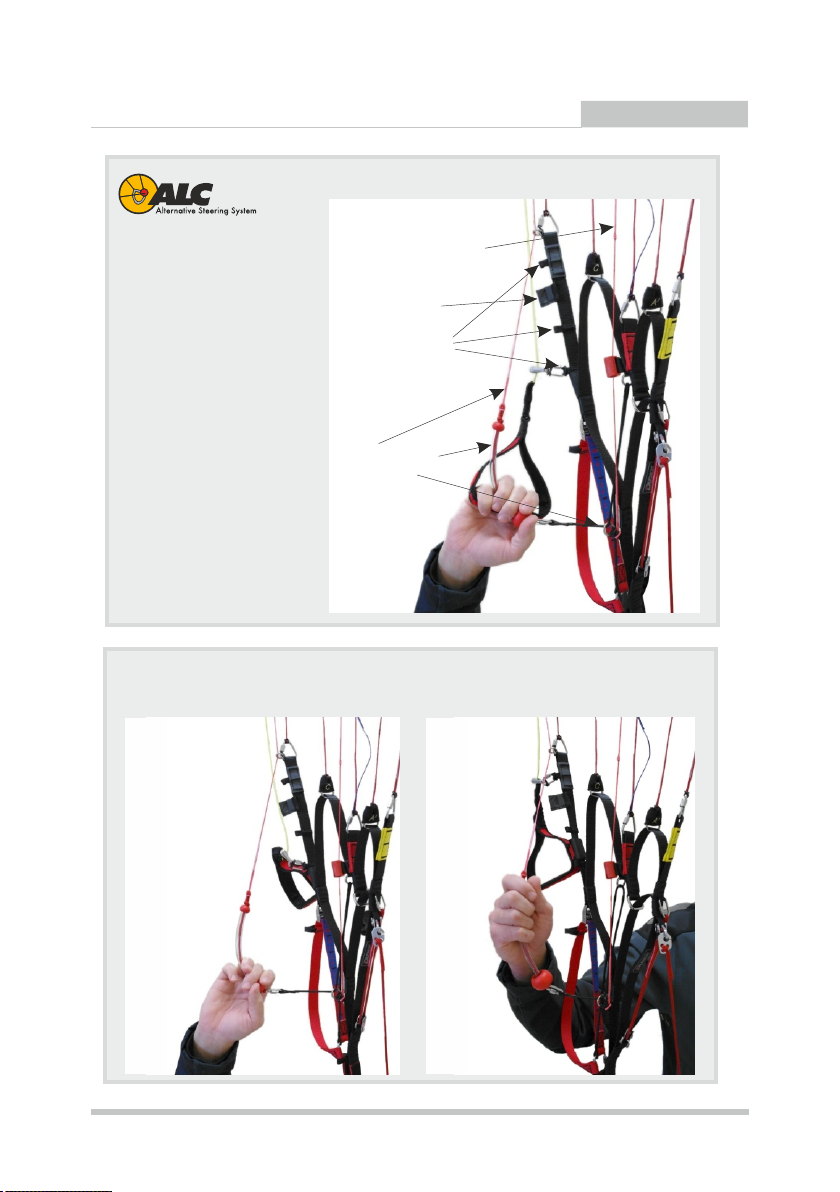
+
USER MANUAL
ALC+ allows for aggressive
TEA - Torque Effect Adjuster
turns even on full speed,
without modifications of
the reflex profile.
This is of special
importance when flying in
Magnetic lock
of the ALC+ handle
three pulley locations
turbulences with open
trimmer and speed system
engaged. Additionaly it is
important for bigger
canopy sizes, without
special solutions
demonstrating problems
associated with big
ALC+:
- line
- handle with ball
- elastic band
steering forces and low
agility.
The steering handle here is
the red ball, easily adjusted
to match personal
preferences.
Two examples how to handle ALC+
9
Page 12
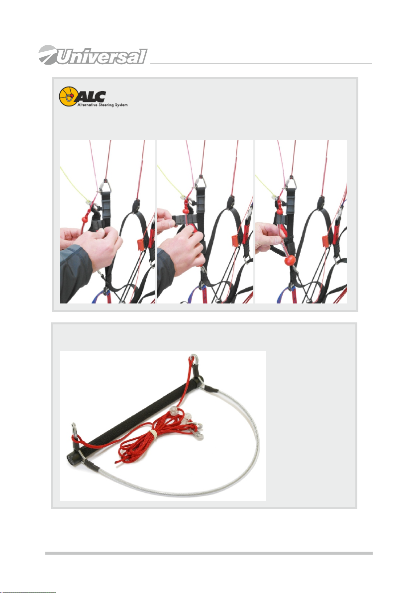
+
Using the magnetic lock of the ALC+ handle
Easy Catch
"Easy Catch"
speedbar is a
godsend for those
who have problems
catching the bar
after taking off. The
speedbar is
designed to stay
always in front of
the speedsystem
lines. Its finish is
very robust, so
long-term service is
guaranteed.
10
Page 13

Triple Comfort Toggle
USER MANUAL
Neodymium magnet of the
Easy Keeper
exchangeable insert
Swivel protects
the steering line
against twisting
slit of the rod
half-rigid
PVC tube
The most soft handle is obtained when no
rigid plastic rod
insertion is used.
Addressing different needs of our clients we have created a TCT system - Triple
Comfort Toggle, making it possible to have your brake handles in rigid, half-rigid
or soft configuration without need to purchase additional handles.
Easy Keeper
Main Steering
Handle (TCT)
- swivel
- Easy Keeper
- TCT
Easy Keeper is our indigenous way to hold the brake handles at the risers by
using strong neodymium magnets. It keeps the handles firmly at the risers, while
both attaching and releasing goes smoothly and easily. The system allows for
easy placing the brake handles on risers during flight, when they are not used,
thus minimalizing danger of getting them into running propeller.
Especially in turbulent air use only the ALC+ system (usage of the main brakes
considerably increases possibility of collapses ).
11
Page 14

WHICH HARNESS?
You can use any certified harness with hang point between 35 cm and 49
cm from the seat (the safest distance being 40 cm).
Width between carabiners should be somewhere between 37 cm and 45 cm,
still in this case the best option is 40 cm too.
Please note that any modification of seat/hang point distance changes the
position of the brakes in relation to the pilot's body. You must remember that
in each harness your typical steering range will be different.
PRE-FLIGHT CHECK
A thorough pre-flight check is essential for any aircraft and the Universal is
no exception.
Having unpacked and laid out the paraglider (in a horseshoe directed
against wthe wind) following checks must be made:
= canopy, lines and risers condition. Do not launch if the slightest
damage is noticed,
= the paraglider should be arranged so that the centre section A-lines
(yellow risers) will strain earlier that the outer ones (A’ - blue risers).
This ensures easy and symmetrical launch,
= cells of the center section must be handled with special care, so that
leading edge stays taut and even,
= all lines and risers should be separated. Make sure they are not
tangled and pay special attention to the A-lines, which should run free
from the A (yellow band) and A’ risers (blue band) to the canopy,
= it is equally important to untangle the brake lines so that they will not
catch anything on the ground during launch. They must be firmly
attached to the brake handles and run freely through the pulleys to
the trailing edge,
= make sure the risers are not twisted,
= it is very important to check that no lines are looped around the
canopy. The so-called ”line-over” may have disastrous consequences
during take off.
Always put on and fasten your helmet before clipping in to the harness.
Check quick links (maillons). Sometimes they can unscrew, especially
when the wing is new.
Check main carabiners. They must be properly mounted, closed and
locked.
12
Page 15

USER MANUAL
3.2.1 LAUNCH
Classic (forward) launch (should be used with little or no wind).
Facing the wind place the risers over your shoulders (A riser must lay on top).
Clip it into carabiners and lock them. Grip the brake handles and A-risers
(marked with yellow band), holding them at the stitching, just under the quicklinks. Spread out your slightly bent hands, keeping them down and back. All
risers but the A should be placed near your elbow joints.
Apply some tension to check if the A risers stay on top and the lines are not
tangled. Take a step back, bow down a little and run forward. After the initial
inflation smoothly move the hands with the risers up and over your head until
the wing will be directly above you. Check the wing and let the A risers loose.
Pump out possible faults and keep an eye on position of the paraglider.
Side drift is corrected best by moving yourself always under center of the
canopy (launch space permitting). In order to keep wing in the air the
suspension lines must stay taut all the time, so in light winds you will have to
run forward. With stronger winds you can control the wing while standing still.
When leaving the ground apply some brakes, then release it after gaining
some distance from the ground. Keep your hands relaxed.
Reverse launch
To be used when wind speed exceeds 3 m/s. After clipping the risers into
carabiners as for the forward launch, turn back to face the wing, moving one
riser group over your head. As a consequence, you will have the risers
crossed.
Unclip the brake handles from rear risers and grip it outside of the risers
without crossing your arms. In this way you steer the right side with you left
hand and left side with your right hand. Now take corresponding A risers on
both sides (still keeping brake handles in your hands).
Make sure that the wing inflates symmetrically and the lines are not tangled.
Building up tension with a few steps back and simultaneously lifting the A
risers (do not pull them towards you) will make the paraglider rise. When it
arrives over your head, stabilize it with the brakes, check again if all lines are
clear and the cells inflated.
When turning into wind, remember to turn the right way (hint: always do it the
same direction) and to keep the lines taut (loaded) at all times. The turn itself
should be quick and smooth. After turning check if the canopy is correctly
inflated, lines and brakes are free & there is free space to launch - off you go,
running into wind with light braking when taking off.
CAUTION: when deflating the canopy in strong winds (e. g. aborting a
launch), use the D risers, not the brakes. Using the brakes in strong wind can
lift the pilot up and drag him/her back.
13
Page 16

3.2.2 FLIGHT
The increased speed range of Universal (in case of trimmers operation) may
demand some attention in flight. Nevertheless, once you have mastered
these additional assets, flying will become pure fun. Good handling will let
you make best use of thermals, and increased speed on transitions means
that your presence in sinking air will be shorter. To avoid stalls when braking
with closed trimmers, their movement is restricted by the tape sewing (Note:
it is possible to push the sewn tape through the buckle with both hands to
replace it, but normal operation range is restricted by said place!).
TURNS
Universal is an agile wing, with smooth reactions to the steering inputs.
Handling is actually easy and forces grow proportionally to position of the
brakes. Adding some weight shift will make the paraglider turn really quick
and tight.
The combined technique (weight shifting and brake input) is by far the most
efficient method.
Turn radius is determined by the amount of inside brake used and weight
shift. Additional application a little outside brake after initiating the turn with
maximum weight shift increases turn efficiency and the outboard wing’s
resistance to collapse (in turbulence, the edge of a thermal etc).
In case of necessary turning in confined area at slow speed (e.g. slope
soaring), it is recommended to steer the decelerated canopy by loosening
the brake at the outside of the turn while applying just a little more brake on
the inside.
NOTE: when entering a turbulent area you should brake a little to put
up the tension. It will allow you to react instantly in case of a problem.
CAUTION: Too hard or too quick pulling of one brake can cause the
wing to enter a spin.
THERMALLING AND SOARING
When flying the Universal minimum sink is reached with slight brake
pressure applied (10 to 15 cm, depending on pilot’s weight).
In turbulent conditions the canopy should be flown with a small amount of
brake applied. This improves overall stability by increasing the angle of
attack of the canopy. The canopy should neither rock back nor surge
forwards, but always stay above the pilot. In order to achieve it, the pilot
should accelerate the canopy by letting off the brakes when entering a
thermal (according to its strength) and brake it on exiting. This is part of
basic active flying that can spare you many potential collapses.
14
Page 17

USER MANUAL
When soaring the slope, minimum height of 50 m above the ground is
recommended for safety reasons. It is important to comply with air traffic
rules, especially when many pilots share airspace close to the hill. The
avoidance manoeuvres often happen to be impossible in such conditions.
FLYING WITH SPEED SYSTEM ENGAGED
When flying into head wind or through sink it is advisable (for the sake of
best glide angle) to increase speed, as long as conditions are not too
turbulent.
Full application of the speed system increases flight speed by some 30%. In
contrast to most paragliders it does not decrease wing stability, in fact the
Universal seems to counter the turbulences even better.
Still, if you meet some serious trouble, it is advisable to release the
speedbar. With application of the speed system the brake forces increase,
and brake effectiveness decreases.
At maximum speedbar and fully opened trims we strongly recommend
steering with ALC system (or TEA lines). Turns executed in this way will
be slightly wider, but strength needed to initiate the turn will be smaller and
there will be no decrease in speed.
3.2.3 LANDING
The Universal is easy to land. Just make sure that last turn into the wind is
done with sufficient altitude, since prior to touch down you should build up
speed, fully releasing the brakes. Then flare out at 1 meters over ground by
gently braking. The glider may climb again for a while gaining some height, if
too much brake is used.
When landing n strong wind you can partly release the trimmers, in order to
have better forward speed.
Strong wind landings hardly require braking, if any at all! Use D-risers
(coloured grey) to deflate the canopy after landing. Using the brakes will
probably result in pilot being lifted and dragged backwards.
The final glide of the landing approach should be straight and smooth. Steep
or alternating turns can result in a dangerous pendulum effect near the
ground.
3.2.4 WINCHING
A lot of successful winches on Universal have been made. Experience
shows that it can be done, but proper attention must be paid.
CAUTION
During start, especially winched or with a motor, always remember to bring
the wing directly over your head. The aerofoil and its angle of attack were
arranged so as to give maximum lift coefficient with relatively high safety
15
Page 18

level. As a result it can stay behind a pilot, if he neglects bringing it directly
over head during launch.
3.3 POWERED FLIGHTS
NOTE: Before each start it is necessary to have a thorough check of the
paraglider,harness and power unit.
In powered flight most of the wing characteristics remain as described
above (chapter 3.2). Still there is additional information needed, concerning
power output, proper matching of the wing/engine/propeller etc. Dudek
Paragliders cannot take responsibility for all possible combinations, but if
you contact us we are always ready to help.
First flights
In order to get familiar with your wing we recommend flying with closed
trimmers first, because in this configuration Universal behaves like a classic
paraglider. Flying like that try pulling the brakes some until you feel
resistance, usually it will be at about 1/4 of the brake travel. Once you feel
confident with your wing, you can start experimenting with faster trim
settings and speed system. Learn to use all of the additional speed and
safety of the Universal.
3.3.1 TAKE-OFF
Classic launch with no wind
Even when it seems that there is no wind at all, it is rarely so. Therefore
always be careful in determining the conditions, since in PPG flying it is
most important that the launch and initial climb are performed with a head
wind (the danger of losing your airspeed while crossing the the wind
gradient is greatly reduced). Special attention must be paid to trees, power
lines and other obstacles, including the possibility of emerging rotors.
Paraglider preparation
Lay out the paraglider downwind of the power unit, with all suspension lines
taut and pointing toward center of the power unit. The risers are to be laid
on the ground. Set the trimmers completely closed. In conditions faster
settings can be advised. Make sure that you warm up the engine while
standing windward of the wing. Stop the engine before clipping in the risers.
Now have a quick check if:
= the helmet is on and locked,
= the risers are clipped in the carabiners,
= the trimmers are properly set,
= the ALC+ handles are fitted to the risers by magnetic lock
= nothing will get in propeller's way,
= speed system is running without problems,
16
Page 19

USER MANUAL
= steering lines and handles are free and not twisted,
= the engine delivers full power,
= take off area is clear of obstacles and free to use.
When you are sure everything is OK, you can clip in the wing and execute
launch as described in paragraph 3.2.1.a.
From now on you should steer the paraglider facing forward, without looking
back over your shoulder (when the wing is low behind you, turning can cause
some lines to get in the propeller). Still, possible fall on your back and
damaging the propeller is dangerous (and costly!) so it should be avoided at
any price, even that of some damaged lines!
During take-off, when you feel the strain on both risers to be equal, make sure
the canopy is overhead, open up full power and lean back to counter the
engine thrust, so that it can push you forward rather than towards the ground.
The best option is not to use the brakes, allowing the paraglider to rise as it
was laid out. If it starts to swerve from its course, just pull the opposite riser
and run under the centre of the wing while preserving starting direction. If the
wind suddenly drops, give a stronger pull on the risers. If the paraglider falls to
one side or back too far to be lifted again - kill the engine, interrupt launch and
check the conditions once again.
As the wing rises, the forces grow lighter and it should stabilise above your
head without overshooting. This is the best moment to check if it is inflated
well and the lines are not tangled, but do so neither stopping nor turning. Once
you feel the forces on the risers decrease, run faster and let go of the risers.
See if there is already any opposition on the brakes and, if necessary, use
them to correct direction or to increase lift at take-off.
Remember:
= If the cage of your power unit is not stiff enough, the risers strained
during launch can deform it to the extent of collision with the propeller.
Before giving it full power, see that the cage does not catch any lines.
= Any brake operation (or steering inputs in general) should be smooth
and gentle.
= Do not try to take off until you have your wing overhead. Hitting power
before that can cause dangerous oscillations.
= Do not sit in the harness until you are sure you are flying!
= The faster the trim setting is, the more brake input is required to take off.
= The lower the hangpoints of your power unit are, the easier is the launch.
Reverse launch in strong wind
Reverse launch can be executed holding in one hand both A risers and one
brake, with throttle and the second brake in the other hand. With a decent
17
Page 20

wind it is by far the best way. In weaker wind it is better to prepare a classic
launch, as running backwards with an engine on your back is not an easy thing
to do.
It is reasonable not to pull the wing up until you are really determined to
launch, especially when it is clipped in.
Lay down the rolled paraglider with its trailing edge against the wind. Unfold the
wing enough to find the risers and check that no lines are looped over the
leading edge. Stretch the risers against the wind, separating the right and left
one.
We suggest that you lay the risers in the same way as you will be turning during
reverse launch, and place one riser over the other, with rear risers upmost. It
should be done this way because once you clip in, the cage of your power unit
will make turning on your own practically impossible. Now run the pre-launch
checklist.
After warming up the engine put the power unit on, turn to face the wing, go to
the risers and clip them in the appropriate carabiners. Pulling on the front and
rear risers open the cells. It is a good idea to pull up the wing briefly in order to
check that the lines are not tangled. Holding the risers, brakes and throttle as
described above, pull the front risers and raise the canopy over your head.
On most occasions you won’t have have to brake it, especially if the trimmers
are partly released. Perhaps it does not agree with your experience, but in this
trimmer setting Universal’s reflex profile stabilizes the wing and does not allow
it to surge forward. Once you have it overhead, turn around, open the throttle
and take off.
As with the classic launch, in this case too you have to find such combination
of trimmers, brakes and throttle settings that will give you the best speed and
rate of climb.
Remember:
= You are launching with your hands crossed. You have to really master this
technique before trying it with a running engine on your back.
= Any brake operation (or steering inputs in general) should be smooth and
gentle.
= Do not try to take off until you have your wing overhead. Hitting the gas
pedal before that can cause dangerous oscillations.
= Do not sit in the harness until you are sure you are flying!
= The faster the trim setting is, the more brake input is required to take off.
When clipping in the crossed risers, you can find proper connection of the
speed system particularly hard. Be careful not to confuse the risers!
18
Page 21

USER MANUAL
Climbing
Once you took off safely, continue heading against the wind, using brakes to
correct rate of climb. Do not try to climb too steeply - attempts to increase climb
rate by pulling the brakes will have an adverse effect - due to the additional
drag actual rate of climb will worsen, and with the throttle fully opened open
even a stall can happen. In powered flight the Universal behaves more like an
aeroplane than a paraglider, and it is good idea to regard it as such. If there are
no obstacles present, it is by far safer (and more impressive for the spectators)
to fly level for a while after take-off and gain some speed before converting it to
height with a brief pull on the brakes. Another reason not to try climbing too
steeply is the risk connected with engine failure at low altitude. Even as
Universal in a steep climb does not stay behind as much as conventional
paragliders do, the low speed is more likely to cause a stall. Besides, you
should always be able to land safely in case of engine malfunction, so it’s
better not to take unnecessary chances and always fly with a safe margin of
speed. Depending on the power unit geometry, it is possible that after take-off
you will notice a propeller torque (turning moment). It will try to turn you around,
so be counter-steer it with a brake or harness cross-bracing. In Universal there
is our TEA system present, making possible to counter the torque in case there
is no cross-bracing. To make TEA work properly you should assembly the line
on proper side (as of propeller direction) and adjust the blocking knot
accordingly to torque force. When climbing steeply with slow trim settings and
high power output beware of the possibility of stall. Due to typical PPG feature considerable vertical distance between thrust axis and wing chord - the range
of safe power operation is closely connected to your skills and equipment.
Power-unit induced oscillations
Certain configurations of engine weight, output and propeller diameter can
cause serious oscillations, during which the pilot is being lifted to one side by
the torque effect, swings down due to his weight, then is lifted again and so on.
To avoid this you can:
= change the throttle setting and/or
= adjust the cross bracing to counteract the torque, if there is one present
and/or
= use the TEA, pulling down the knot through the tube, simultaneously
blocking it in the slit and/or
= shift yourself to the other side of the harness and/or
= change the trimmer setting.
The best method is to fasten opposite cross-bracing, or apply some weightshift. Such oscillations usually occur at full power - the greater the engine
output and propeller diameter, the bigger the swings. In addition there are often
19
Page 22

too late or wrong pilot reactions, increasing the problem instead of solving it. In
this case the safest way to deal with this question is to close the throttle and
release the brakes.
Especially less-experienced pilots tend to overreact. This is called a pilotinduced oscillation, and proven solution is to leave the brakes alone.
3.3.2 LEVEL FLIGHT
Once you have gained safe height after take-off and wish to go for a route, you
can turn onto the right direction, fully open the trimmers and let off the brakes. If
the conditions are turbulent, it can look foolhardy, but this is the essential
feature of the reflex profile - the faster you fly, the the safer your wing is. That's
why it’s truly possible to release the brakes and enjoy your flight.
CAUTION: Some pilots with previous free-flying experience may have a
well-grounded habit of keeping the brakes slightly applied at all times.
Such a technique, while quite reasonable on a free-flying wings as it
allows for quick pilot reactions and decreases sink, is not advisable on
reflex-profile paragliders. When you pull the brakes, the Universal profile
loses its reflex characteristics (see next page).
If you have a variometer or altimeter aboard – watch it. In level flight it is very
easy to start climbing unintentionally. The instruments will help you optimise
speed and fuel economy.
Of course each flight will depend on current configuration of your gear, but due
to its ability to fly safe without constant piloting the Universal will let you adjust
everything to the best effect. Good knowledge of weather conditions (e.g. wind
at different altitudes and smart use of thermals or dynamic lift will help you
greatly reduce fuel consumption and increase flight range. Of course the
engine is always there to bring you in the right place.
Do not hesitate to lead the Universal into tight thermalling in order to win some
altitude and spare fuel. In order to make the best of the thermal, completely
close the trimmers.
Trimmers and speed-system operation
The reflex wing airfoil enables the Universal pilot to use a wide range of
trimmers and speed-system action. You are free to experiment with all possible
settings, as long as you are on safe altitude. Fully opened trimmers increase
the speed and stability of the wing, and with it also its ability to cope with
turbulences and overall penetration. As forces on the brakes grow at high
speeds, the weightshifting or steering with ALC+ system becomes increasingly
effective.
ALC+ system can be used in all trimmers and speed system settings, also
in combination with main steering handles when trimmeri is closed. At
maximum speedbar and/or fully opened trims we strongly recommend
steering with ALC+ system or TEA system, especially in rough air.
20
Page 23

USER MANUAL
Influence of classic steering on the reflex profile
Pilots used to classic paragliders tend to fly "active" style, with their brakes constantly tensioned.
Flying a reflex wing like that is ineffective and can possibly be dangerous.
Basic rule of reflex paramotoring says: the more turbulent it is, the more trims should be
released and classic steering should be limited, especially with speed system engaged.
In such moments paraglider is much more effectively steered by TST or ALC+ systems, designed
specifically for that reason.
Problem is illustrated by following drawings:
Released trims without brakes
Typical setting for fast and safe flying. Center of
pressure of the aerofoil moves forward, practically
excluding collapses. Pitching moment induced by
the reflex aerofoil increases angle of attack.
Released trims with brakes applied
Even slight brakes application (especially on full
speed bar) shifts the center of pressure back, and
due to lack of reflex on trailing edge, pitching
moment now decreases angle of attack.
Additionally turbulence behind the wing occurs. In
some circumstances this can lead to a collapse.
Using the brakes can be sometimes necessary for
heading corrections, still you should keep your
brakes free when flying ahead, otherwise the reflex
feature doesn't work.
Closed trims
In this configuration brakes are the normal and
prescribed steering system. Slow trim is used for
launching in nil wind and thermalling. The canopy
behaves similar to classic profile paragliders, with
slightly increased tuck resistance.
lift
speed
sink
pitching moment
center of pressure
Turns executed in this way will be slightly wider, but strength needed to initiate
the turn will be smaller and there will be no decrease in speed.
Please note the wide operational speed envelope of the Universal achieved by
trimmers only. Due to such wide range we’ve decided to introduce capability of
restricting that range (before the launch) by the pilot according to his skills and
preferences. Even when the trimmer range is restricted by half, applying the
speedbar in urgent needs allows for almost maximum speed. Restricting the
trimmer range is shown in „Adjusting the trimmers” appendix in this manual.
At slower trimer settings both the sink and steering forces decrease, so it is
possible to efficiently use the thermals. Study drawings of trimmers and speedsystem adjusting and setting, as well as their influence on the wing shape.
21
Page 24

When flying in slow configuration turns can be much tightened and more
effective by means of differential brake operation. Slight use of the outer
brake (with considerable amount of the inner one) will diminish the loss of lift
in turn. Turns can be much improved by additional use of throttle, speedsystem etc.
Once with growing experience you will master these techniques, you will be
able to execute fully coordinated and effective turns, bringing to mind the
aeroplane handling.
REMEMBER:
=
Trimmer setting is another part of the pre-start check list!
=
If it will be asymmetric, the wing will be turning all the time. And if you
will inadvertently set them off, the reflex profile of the Universal will
keep the wing level, so after opening the throttle you'll start to descend
with increased speed instead of climbing.
3.3.3 LANDING
In PPG flying there are two kinds of landing: with and without power.
Power off landing
At an altitude of 50 metres switch the engine off and glide as you would on a
conventional paraglider. It reduces the chances of damaging the propeller on
landing, but on the other hand there is only one attempt possible - so it has
to be done right! With or without power Universal better copes with
turbulence on partly open trimmers (i.e. some 6 cm, position ‘6’). So, if the
conditions are rough, better make an approach with greater speed, plan a lot
of free space (as for a hangglider) and wear that speed off before touching
down. Universal preserves the energy well, so there is a long float
necessary, exchanging the abundant speed for lift with your brakes.
If the landing field is not big enough and you have to land on the spot, we
advise you to set the trimmers in slower settings. It will increase lift
coefficient of the wing, effectively decreasing its sink rate and speed. Such
an action is especially important when flying with high surface loading.
Powered landing
Make a flat approach with the engine idling, then level out and lose the
speed before final flare. Immediately after touchdown switch off the engine.
The main advantage of this procedure is of course the possibility of a
repeated approach if anything goes wrong. Still, if you forget to switch off the
ignition before the wing falls down, there is a considerable risk of damaging
propeller, catching lines in it or even suffering injuries connected with falling
on your running engine.
Remember:
=
Whenever possible, get to know the landing field before taking off.
22
Page 25

USER MANUAL
=
Check the wind direction before planning the approach.
=
Landing with power off requires much less space.
=
In case of any doubt, practice the landing until you feel totally safe.
3.3.4 GOLDEN RULES!
=
Never place the power unit downwind of the paraglider.
=
Check, double check and then check once again if there is no fuel
leakage.
=
Do you have enough fuel for the flight? It is always better to have
toomuch than too little!
=
Check if there is nothing loose in the harness, that could possibly contact
the propeller in flight.
=
Whenever you encounter a problem, fix it AT ONCE however small it is!
=
Always put on and lock the helmet before getting in the harness.
=
Before each launch run a full pre-flight inspection.
=
After landing, control the wing facing the direction of flight, as on turning
you always risk getting lines in the propeller. Turn only if there is danger
of falling on your back.
=
Do not ask for trouble - do not fly over water, between trees or power lines
and other places where engine failure will leave you helpless.
=
Mind the turbulence caused by other gliders or even by yourself,
especially when flying low.
=
It is not reasonable to let go of the brakes below 100 meters, because a
possible power unit malfunction may require immediate attention.
=
In general never trust your engine, as it can stop at any moment. Always
fly as if it’s exactly what it's going to do.
=
Unless it is absolutely necessary (e.g. collision avoidance), do not
execute tight turns against the torque direction. Especially when climbing
you can easily enter a stall and consequent negative spin.
=
Do not fly with tail wind at low altitudes, as it pretty much narrows your
options !
=
Do not wait for the problem to grow - any change of engine sound or a
vibration can indicate troubles. You'll never know until you land and check
it out!
=
Be certain of your navigation
=
Remember that not everyone is fond of your engine noise. Do not scare
the animals.
23
Page 26

3.4 QUICK DESCENT METHODS
3.4.1 BIG EARS
In order to get the big ears you have to pull down the outer lines of the A' risers
(distinguished by blue sheath) by some 20-50 cm. While inducing big ears you
should never let the brakes out of your hands.
After tucking the tips in, Universal will continue to fly straight with increased sink
rate (up to 5 m/s). You can steer the wing pretty efficiently by weight-shifting.
After releasing lines, the paraglider will usually open up on its own or you can
assist it with a long stroke of the brakes. For the sake of safety (the possibility of
a parachutal stall) it is reasonable to engage speed system after pulling big ears
in order to lessen the angle of attack of the wing centre. Executing big ears with
opened trimmers is very difficult due to reflex profile stabilisation.
CAUTION: See the PARACHUTAL STALL chapter.
Never try to pull big ears during powered climb, as the increased drag can
lead to increase of the angle of attack and a parachutal stall.
Besides, pulling the ears while climbing is pointless anyway.
3.4.2 SPIRAL DIVE
Universal is a very agile paraglider, so entering spiral dive happens very quickly
and can be surprising for the less experienced pilot. A spiral dive is characterised
by reaching the highest sink rates possible. Significant G-forces, however, make
it difficult to sustain a spiral dive for long, as will place high loads on both pilot
and glider to degree of losing consciousness by the pilot. Never do this
manoeuvre in turbulence or at too high bank angles. Control the dive and do not
exceed 16 m/s sink. If the dive is not stopping after releasing the brake,assist the
glider with the outer one.
NEVER DO BIG EARS IN A SPIRAL! In this manoeuvre smaller number of
lines is carrying an excessive load mulitplied by the centrifugal force, what
can lead to damage of the lines or even the paraglider itself (load of a
single line can be much higher than passed in certification trials (i.e. 8 G).
3.4.3 B-STALL
B-stall can be executed only with fully closed trimmers (i.e. pos. ‘0’).
To enter a B-stall, simultaneously pull down both B-risers (red tape) by 10 – 15
cm. The canopy will collapse across the entire span along its B-row, the airflow
over top surface will break and canopy surface will be decreased. Forward
movement will be almost completely stopped. Further pulling B-risers is not
advised, as tests have shown it to increase wing instability. If the canopy forms a
horseshoe with both wingtips in front of the pilot, gently apply both brakes to
recover.
24
Page 27

USER MANUAL
To exit a B-stall, the risers should be released in a smooth and decisive
manner. On quick and symmetrical releasing B-lines the airflow will be
reinstated and the wing will surge forward, returning to normal flight. In
contrast to standard paragliders, in case of Universal there is no need to
counter this surge with brakes - yet another asset of the reflex profile!
CAUTION: See the PARACHUTAL STALL chapter. All rapid descent
techniques should be practiced in smooth air and only with sufficient
altitude only ! Full stalls and spins are to be avoided as recovery
procedures, of the extreme manoeuvres, since irrespective of paraglider
type they may have dangerous consequences!
BY FAR THE BEST TECHNIQUE IS SAFE AND CORRECT FLYING, SO
THAT YOU WILL NEVER NEED TO DESCEND RAPIDLY!
3.5 AEROBATICS
Universal was not designed to do any aerobatics.
3.5.1 WING OVER
You make a wingover by performing a series of consecutive, alternating turns
with growing bank angle. Too much banking connected with some flaws in coordination and execution can evoke pretty dynamic collapse.
CAUTION: Steep turn with bank angle over 60 degrees is a prohibited
aerobatic manoeuvre!
3.6 EXTREME MANOEUVRES
CAUTION! EXTREME FLYING MANOEUVRES SHOULD ONLY BE
CARRIED OUT DURING SAFETY TRAINING COURSES (SIV, INSTABILITY
TRAINING) UNDER PROPER GUIDANCE! WHILE PROVOKING OR
EXITING REAL SITUATIONS THERE IS DANGER THAT YOUR ACTIONS
WILL PROVE TOO QUICK OR TOO STRONG, SO YOU SHOULD ALWAYS
EMPLOY GOOD JUDGMENT, STAY CALM AND TAKE MEASURED
ACTIONS.
Since all actions required to exit or prevent dangerous situations on
Universal are typical and pilots flying this wing should already have
proper experience, we are going to describe only the characteristic
features of the Universal. Description of standard methods dealing with
extreme situations can be found in textbooks.
3.6.1 ONE SIDED COLLAPSE
Even when the trimmers are fully opened or the speed system is engaged,
collapses practically do not occur and can be induced only by a very strong
turbulence.Still, if it happens, a little counter-steering is enough to keep the
Universal on course. Under normal conditions with collapses up to 50% of the
25
Page 28

wingspan, Universal will reinflate instantly and spontaneously. If it will not
happen, you should aid this process by application of brake on the collapsed
side.
3.6.2 FRONTAL COLLAPSE
The reflex profile of the Universal makes it practically impossible, especially at
higher speeds. During tests we succeeded in creating this situation only with
fully closed trimmers and using special measures. Such forced collapses can
lead to extremely deep collapses, so recovery will require decisive pilot action
(short and equal application of both brakes).
3.6.3 FULL STALL AND NEGATIVE SPIN
Practically do not occur, may happen only as a result of serious neglect or
intentional action of the pilot. You have to be careful when flying at low speeds
until fully familiar with brake operation. Wing recovers spontaneously in initial
phase of stall, otherwise use standard procedures.
3.6.4 DEEP STALL
Under normal conditions does not occur. If you want to prevent it happen at all,
simply stick to a couple of rules:
=
after B-stall, release the risers quickly and evenly. Don’t be afraid Universal does not jump forward excessively.
=
after big ears execution, engage the speed system. This will increase both
the sink rate and safety margin, as big ears constitute an aerodynamic
brake with significant loss speed.
Nevertheless, if such a parachutal stall happens e.g. due to strong turbulence,
simply apply some pressure on speed bar and/or push the A risers forward. You
can release the trims too.
3.6.5 LINE OVER AND CRAVATTE
Universal is a modern wing which, in order to decrease drag, has fewer
suspension lines and greater distances between them. Therefore it's always
possible that after a tuck one of the stabilisers may tangle in the lines. Usually a
couple of pulls with a brake settles the matter.
If it's not enough, try to untangle it with big ears or a stronger pull on the
risers.In case of any doubts you should seriously consider a rescue chute. It is
there as a normal equipment part, not just an ornament.
3.6.6 EMERGENCY STEERING
In case of any malfunction that renders normal steering impossible, you can
safely steer and land Universal using the D-risers (grey marking) or stabilo
lines.
26
Page 29

USER MANUAL
4. PARAGLIDER CARE
Proper looking after your paraglider will prolong life of your Universal.
4.1 FOLDING AND STORAGE
Universal features a number of recent technologies, like tensioning the leading
edge with a plastic string. That's why the paraglider should be folded with care
in order to keep it healthy during transport and storage.
Basic rules to be observed when folding:
1. We fold the canopy together on rib-to-rib, cell-to-cell basis (like a
harmonium). We don't break the wing in halves, taking the stabilizers towards
centre.
2. After creating a package along the maximum chord, we don't roll it, but fold
two to three times (depending on the chord length) from trailing to the leading
edge.
3. Leadin edge stays on top of the folded canopy.
Store the paraglider in a dry place, away from chemicals and UV exposure.
Never pack or store the glider when wet.
Remember that the wing becomes damp also while lying on green grass in
direct sunlight.
A good precaution to avoid dampness and/or UV when you have to wait in a
start queue is to use quick-pack after rigging up.
Always dry the glider thoroughly before packing and/or storage. Never pack you
paraglider too tightly.
While drying, never expose your paraglider to direct sunlight operation.
Please note that with frequent kiting/groundhandling exercises your paraglider
will deteriorate faster due to its repeated rising, falling and being dragged on the
ground.
4.2 CLEANING
Clean the paraglider with water and a soft sponge. Do not use any chemicals or
alcohol, as these can permanently damage the fabric.
4.3 REPAIRS
Repairs should only be carried out by the manufacturer, authorised distributor or
authorised workshop. It is acceptable to fix minor cloth damage with the selfadhesive patches included in the package.
4.4 DETERIORATION: A FEW TIPS!
The Dudek Universal is made mainly of nylon - a fabric which, like any other
synthetic material, deteriorates through excessive exposure to UV rays that
come with the sunlight. Hence it is recommended to reduce UV exposure to a
minimum by keeping the paraglider packed away when not in use. Even when
packed in a bag, it should not remain in the sun for long.
27
Page 30

Universal’ suspension lines consist of Technora inner core and polyester
sheath. Submitting them to excessive loads in flight should be avoided, as it
can cause irreversible damage.
Keep the paraglider clean, since getting dust in the lines and fabric will reduce
their durability.
Be careful to keep snow, sand or stones from entering the cell openings: their
weight can slow or even stall the glider, and sharp edges can damage the
cloth.
Prevent lines from catching anything, as they can overstretch or tear. Do not
step on the lines.
Uncontrolled strong wind takeoffs or landings can result in the leading edge of
the canopy hitting the ground hard, which may seriously damage the ribs,
sewing and surface material.
Knots can chafe suspension and/or brake lines.
Check line lengths after tree or water landings, as they can stretch or shrink.
A line plan is included in this manual or may be obtained from the dealer when
needed. After landing in water you should check the wing fabric as well, since
the wave forces can cause the fabric to distort in some areas. When taking
the wing out of the water, always do this by trailing edge, so that water can
flow out freely. After a sea landing, rinse the paraglider with fresh water. Since
salt crystals can weaken the suspension lines even after rinsing in fresh
water, you should replace the lines with new ones immediately after contact
with salt water.
Every second year Universal should undergo technical inspection by
the manufacturer or authorised distributor.
28
Page 31

USER MANUAL
5. TECHNICAL DATA
Universal 23 25,5 28 31 34
Certification EN
Number of cells
Surface area (flat) [m2]
Surface area (projected) [m2]
Span (flat) [m]
Span (projected) [m]
Aspect Ratio (flat)
Aspect Ratio (projected)
Sink rate [m/s] min = 1,1; trim = 1,3 - 2,2; max = 3,0
Speed [km/h] min = 23; trim = 37 – 52; max = 57
Max. cord [cm]
Min. cord [cm]
Distance pilot to wing [m]
Total line lenght [m]
Weight range EN [kg]
Weight range DGAC [kg]
Weight [kg]
Lines Technora: 1,2 & 1,3 & 1,5 & 1,8 & 2,3
Fabric Dominico tex 34 & 41 g/m2
Risers
B B B B -
50 50 50 50 50
23,00 25,50 28,00 31,00 34,00
19,83 21,98 24,14 26,72 29,31
10,83 11,40 11,95 12,57 13,17
8,71 9,17 9,61 10,11 10,59
5,10
3,83
261,20 275,10 288,20 303,30 317,60
60,10 63,30 66,30 69,80 73,10
6,82 7,18 7,53 7,92 8,29
344,01 362,82 380,74 401,20 420,70
60-75 70-95 90-115 110-140 135-170
60-95 70-115 90-140 110-170 135-215
6,1 6,6 6,9 7,5 7,8
Dominico Tex Hard 40 g/m
SR Scrim, SR Laminate 180 g/m
PASAMON - Bydgoszcz, Polska
2
2
29
Page 32

6. WARRANTY AND AEROCASCO
Purchase of a new paraglider is a serious expense for any pilot. That is why
we cover our paragliders with extensive warranties and additionally offer an
AeroCasco insurance against damage and repair costs.
WARRANTY
Dudek Paragliders guarantees free of charge repairs caused by the material
or production faults along following scheme:
For the free-flying paragliders warranty covers
36 months (3 years) or 300 flight hours (depending on
what comes first).If the paraglider is used for powered
flights, every hour spent in the air should be counted
as two (does not apply to dedicated PPG canopies).
For the PPG paragliders warranty covers 24 months
(2 years)/200 flight hours (depending on what comes
first).
For the mountaineering (MPG) and speedflying wings
as well as school and profit users warranty covers
18 months (1.5 year)/150 flight hours (depending on
what comes first).
WARRANTY DOES NOT COVER:
= canopy colour fading
= damage caused by chemicals or salt water
= damage caused by incorrect use
= damage caused by emergency situations
= damage resulting from accidents (airborne or not)
= WARRANTY IS ONLY VALID IF:
= flight hours are correctly registered in the logbook of the owner (and
possible earlier owners), distinctly marking PPG flights,
= the paraglider is handled in accordance with the operating manual,
= the purchaser has not carried out any repair by him/herself (excl.
minor repairs with self-adhesive patches),
= carried out any modifications,
= the paraglider can be unmistakably identified
= the paraglider was being inspected according to prescribed timetable.
If you have ought your paraglider second-hand, ask its previous owner of the
paraglider for a logbooks copy (total of flying hours since the date of first
purchase).
30
Page 33

USER MANUAL
When repairs or inspection is necessary, please contact your dealer. He will
assess the situation and advise on further actions (consulting us when
necessary).
AEROCASCO
Normal warranty does not cover repairs of damages
caused by the user or a third party. As costs of such
repairs can be considerable, Dudek Paragliders offer an
AeroCasco insurance. It covers a one-off repair of any
mechanical damage, no matter how big and whoever
inflicted them.The only expenses the purchaser has to
pay are shipping costs and so-called share-of-cost
amount.
AeroCasco can be purchased only for a brand new
paraglider (at the paraglider purchase). Its cost is 50 euro.
NOTE: AeroCasco is not available for all paragliders (check this before
purchase). It can be obtained for privately used wings only.
AeroCasco applies only to damages that took place during take-off, flight or
landing. Obviously, all faults in the material and manufacturing flaws are
covered by normal warranty.
When handing the paraglider for the repair you have to present a card
confirming its AeroCasco status. After the repair you will have to cover only
the share-of-cost value of 50 euro.
AeroCasco is valid for one repair only.There is a possibility to extend
AeroCasco for one more year. To do this you have to send your paraglider
for inspection not later than a year after the date of purchase. Extension fee
is 75 euro (incl. inspection).
Remember to attach the AeroCasco confirmation on expedition.
AeroCasco does not apply to any of the following: theft, colour fading,
damage caused by incorrect storage or transport, damage caused by
chemicals, salt water and force majeure.
31
Page 34

7. WHAT HAVE YOU BOUGHT
The Dudek paraglider that you bought should have the following items:
= the paraglider itself (canopy, lines and risers)
= transport bag (with compression strap)
= Duralight - backpack
= FastBag (quick-pack)
= a speed system with Easy Catch bar
= a windsock
= a pocket with paper work and repair wallet including:
= A piece of self-adhesive fabric (10 cm x 37.5 cm) for small repairs.
Note that even small tears located in the vicinity of stitches have
to be repaired by an authorised service
= A looped and stitched suspension line longer than the longest line
used in the paraglider that is to be used as a temporary
replacement. Do not cut it if you have to replace a shorter line,
just tie it at the length needed
= A paraglider passport with entered date of purchase and valid
technical inspection (please check the serial number with the
sticker on the wing tip)
= The User Manual you are reading
= Small gifts.
32
Page 35

USER MANUAL
SUMMARY
If you respect the rules of safe flying and proper glider care, you will enjoy
many years of pleasant airtime. Still, you must be aware of possible dangers
and face them wisely. You must accept the fact that all air sports are
potentially dangerous and your actual safety depends solely on you.
We insist that you fly safely, and this concerns both the weather choice and
safety margin during all manoeuvres.
FLYING THE PARAGLIDER IS ALWAYS YOUR OWN RESPONSIBILITY.
SEE YOU IN THE AIR!
8. RIGGING SCHEME
Rigging (suspension lines) scheme is on the next page, while tables of lines'
lengths are published in Service Documents on our website www.dudek.eu
33
Page 36

34
Page 37

USER MANUAL
9. RISERS: DESIGN AND ACCESSORIES
Figure 1 Risers in lower hangopint configuration (steering line is led through one
pulley only).
steering
line
upper
pulley for low
hangpoints
swivel
magnetic lock
of the ALC+ handle
adjustable Easy
Keeper magnet
ALC+
handle
brake
handle
trimmer buckle
plastic trimmer lock
D
ALC+
line
C A'
B
A
TEA cord
TEA lock
middle and lower
pulley locations
– high hangpoints
speed
system
hook
trimmer
handle
exchangeable
trimmer strap
additional inner loop
elastic band
speed
system
pulleys
carabiner
35
Page 38

Figure 2
Low hangpoint (steering line is led
through a pulley in upper position).
Magnetic clip is also placed high.
Figure 3
High hangpoint (steering line is led
through a pulley in lower position).
Magnetic clip is also placed low.
36
Page 39

USER MANUAL
Figure 4 TEA cord inactive (a) and engaged (b)
a
Figure 5
You can reduce drift of the paraglider (contrary to propeller rotation) with TEA or
the additional inner loop in the risers hangpoint, visible nearby. Bear in mind
though, that with TEA you can set a knot exactly where it’s needed to compensate
torque accurately, while simple loop does not have any adjustment.
b
knot
37
Page 40

Figure 6
Steering systems
scheme
Here is a simple guide
to find your way in a
maze of risers and
their various handles.
Classic brakes
operate along entire
trailing edge, ALC+
system is active on
the outer parts of the
trailing edge, and the
TEA affects stabilizer
only.
With this arrangement
the pilot has full range
of steering systems at
his disposal and can
freely choose between
them, according to his
needs and current
situation.
TEA
line
TEA lock
Magnetic lock of the
ALC+ handle
ALC+ handle
38
Additional pulley
locations
Brake handle
(classic brake)
Adjustable Easy Keeper
magnet
elastic band
Page 41

Figure 7 Trimmers influence on the wing profile
USER MANUAL
Trimmers closed
Minimal speed and
minimal sink
Take-off position
neutral configuration
risers length:
A, A': 460 mm
shortening [mm]:
Trimmers in “6”
position
Risers of equal length.
Transitional position
neutral configuration
risers length:
A, A’, D: 460 mm
B, C: 465 mm
Trimmers fully opened
Maximum speed
neutral configuration
risers length:
A, A': 460 mm
lengthening [mm]:
70 70 4565 40 15
D C B A’ AD C B A’ AD C B A’ A
39
Page 42

Figure 8 Trimmer settings influence on speed-system action
Lengthening and shortening values are given in respect to neutral risers length: 460 mm
Full acceleration with closed trimmers:
good speed, easy steering, decreased
stability. Classic speed-system action.
shortening [mm] shortening [mm]lengthening [mm]
Full acceleration with opened trimmers:
small angle of attack, maximum speed.
Great stability and hard steering.
Advised use of ALC+ system or TEA.
130 50 30 8065 70 75 80
D C B A’ AD C B A’ A
40
Page 43

Trimmer operation tips
USER MANUAL
rimmer
T
strap
Launch
Thermalling
Brakes/ALC
TEA as TST
SLOW
FAST
closed released
MODIFIED
REFLEX
AIRFOIL
Brakes
Torque effect adjuster can be used for correcting flight
direction in fast configurations too (trimmers/speed
system). It works the same way as the TST used in our
Main brakes and the ALC can be used both simultaneously
and/or alternatively. The brakes will be more effective at
slow settings, while the ALC at faster ones.
FULL REFLEX
AIRFOIL
older paragliders..
ALC
Thermalling is most effective at closed trimmers. In
case of strong turbulence it is advisable to partly open
the trims, thus increasing overall stability.
In nil wind conditions the launch is easiest at completely
closed trims. The stronger the wind, the more you can open
the trimmers. Nevertheless, launch on fast trim settings will
be hard or outright impossible (depending on wind speed).
41
Page 44

Leading
edge
Trailing edge
Cell
Main
suspension
lines
Stabilizer
Fot. Iwona Dudek
Risers
Page 45

MADE IN
EUROPE
V 20.10.2014
 Loading...