

Page 1
user manual
Page 2

NOTE!
Please read this manual carefully before your first flight
Very important!
Before use it is vital to check in which configuration the steering lines and pulleys
are currently set (lower or upper hangpoints) and adjust them to your preferences if
necessary.
The risers have three points to fix the pulleys on – lower, middle and upper one
(see risers on page 11). On each main steering line there are points marked,
to fix the steering handle corresponding to the middle position of the pulley. Position of
the handles should be adjusted according to your pulley setting.
Steering lines must not not push down the trailing edge when not operated – this must
be observed in all possible configurations of trimmers and speed-system. Steering lines
must have a couple of centimeters play before they engage affect the canopy (see
section 3.1 on the proper adjustment). For sake of safety it is always recommended to
set the brakes rather too loose than too tight. Make sure they are set symmetrically, too.
Ill-adjusted steering lines may cause you to misinterpret the canopy’s
behaviour in flight, and may cause dangerous collapses in accelerated flight
when set too short.
Speed system of these risers is by default integrated with the Power Attack system.
During numerous tests it turned out that in case of certain slalom tasks it is better to
restrain the trimmer a bit, so that it won't become totally released when acting jointly
with speed. Such settings make it possible to use the main brakes for steering in
accelerated flight, without collapsing tips.
Correct operaiton of the Power Attack requires releasing the trimmers beforehand by at
least 6 cm and not more than 9 cm.
Using the speed system combined with Power Attack results in big surge of the sink.
This can surprise an unexperienced pilot, causing dangerous situation when close to
the ground.
If you intend to operate the trims independently of the Power Attack system, you have
to disengage the hooks joining the PA and the trimmers.
DO NOT USE THE SPEED SYSTEM WITH CLOSED TRIMMERS OR THE POWER
ATTACK SYSTEM BLOCKED! SUCH ACTION MAY CAUSE VIOLENT COLLAPSES!!
CORRECT SPEED SYSTEM OPERATION REQUIRES
RELEASING TRIMMERS BY AT LEAST 6 CM!
When flying at full speed (trimmers opened / trimmers opened and speedbar
pushed), in rough air, it is highly recommended to steer the paraglider using alternative
steering methods like TCL ( (Tip Control line) and conected TST toggle .
With increasing speed an effect of „inverting” the profile when trailing edge is being
pulled down emerges. That effect can cause dynamic collapses, especially at full
speed.
The safest way to change your course at high speeds is to use the TST and TCL lines,
or (in the order of safety) the outer lines of the 2D steering system. Any steering inputs
should be smooth and easy, without sharp and/or deep movements. Such actions can
dynamically change pressure distribution over the airfoil, leading to collapses.
These warnings affect every paraglider and the Snake XX is no exception!
Page 3

Page
TABLE OF CONTENTS
2. The wing..............................................................................................5
2.1 Design
2.2 Structure
3. Flight operation............................................................................10
3.1 Steering system
3.2 Before you fly
3.3 Take off
3.4 Level flight
Free flying
3.7.1 Take-off
3.7.2 Flight
3.7.3 Landing
3.7.4 Winching
3.8 Quick descent methods
1. Introduction......................................................................................4
3.5 Landing
3.6 Golden rules
3.7
3.8.1 Big Ears
3.8.2 Spiral dive
3.8.3 B-stall
3.9 Extreme situations
3.9.1 Side collapse
3.9.2 Symetric collapse
3.9.3 Full stall and negative spin
3.9.4 Deep stall
3.9.5 Line over and cravatte
3.9.6 Emergency steering
4. Canopy care........................................................................................32
4.1 Storage
4.2 Cleaning
4.3 Repairs
4.4 Deterioration - a few tips
5. Technical data......................................................................................35
6. Warranty, AeroCasco..........................................................................36
7. What have you bought.......................................................................38
8. Rigging scheme ..................................................................................39
Page 4

1. INTRODUCTION
CONGRATULATIONS!
We are pleased to welcome you among ever growing community of pilots
flying DUDEK PARAGLIDERS. You’ve become a proud owner of state-ofthe-art sport PPG wing.
Intensive development, application of the most modern production methods
and thorough testing resulted in a friendly behaving paraglider, offering the
pilot a lot of fun combined with great performance.
With many years of experience we are confident to pronounce Snake XX to
be the best paraglider in its class.
We wish you many enjoyable flight hours under your new Snake XX!
DISCLAIMER
Please read this manual carefully and note following points:
■ The purpose of this Manual is to offer guidelines to the Snake XX pilot
and it is by no means intended to be used as a training manual for this
or any other paraglider.
■ You may only fly a paraglider when qualified to do so or when
undergoing training at an accredited school or with an instructor.
■ Pilots are personally responsible for their own safety and their
paragliders’ airworthiness.
■ The use of this paraglider is solely at the user's own risk! Neither the
manufacturer nor dealer do accept any liability connected with this
activity.
■ This paraglider on delivery meets all the requirements of the EN 926-1
and 926-2 regulations or has an airworthiness certificate issued by the
manufacturer. Any alterations to the paraglider will render all its
certificates invalid.
NOTE
Dudek Paragliders warns that due to constant process of development the
actual paraglider may differ slightly from the one described in the manual.
Possible differences will not affect the fundamental design parameters:
technical data, strength and flight characteristics. In case of any doubts
please contact us.
4
Page 5

2. THE WING
For whom the Snake XX?
This is a demanding wing for demanding pilots.
Highest performance available for fast slalom courses, with possibly best agility. It's
truly a champion's wing.
Despite highest aspirations we did our best to preserve legendary stability, known
from our other reflex paragliders.
2.1 DESIGN
Development of the Snake XX was focused on improving canopy
performance. Shark nose profile gives better airflow on the leading edge and
higher air pressure within canopy at any angle of attack. The leading edge
features synthetic rods (Flexi Edge Technology), considerably improving
launch characteristics and protecting against collapses at high speeds.
Additionally, front part of the canopy is further stabilised with the LE2R
technology (Leading Edge Double Reinforcements). Higher aspect ratio, a bit
more cells and modified arc gives result in better economy and agility of the
wing.
Snake XX is a 4-row canopy. Only in such configuration full range of aerofoil
geometry can be successfully achieved, combining trimmers, speed and
Power Attack systems.
B riser is anchored on additional pulley on the B riser, minimalizing drag during
speed-system operation (previously it was a simple quicklink).
Main suspension lines comes with a polyester sheath, covering Technora fiber
core. All lines of the upper level are unsheathed.
The Snake XX as standard is equipped with 2D steering system
consists of two main steering going out of one handle, i.e. inner
line, led through the pulley and affecting central 2/3 of the trailing
edge, and the outer one, connected directly to the outer 1/3 of the
canopy.
Due to such division, experienced pilot can modify steering progression
according to his own preferences. Everything depends on the pilot’s wit and
experience. Those, for whom the Snake XX is intended, will be able to tune
the steering system in their own style.
Fundamental feature of a good PPG canopy should be its great stability and
tuck-resistance. When this is achieved, user does not have to concentrate all
the time on piloting in turbulent air, thus saving energy for navigation, taking
pictures or simply enjoying the flight. In addition the faster and safer your
paraglider is, the more often you can fly. While the Snake XX was designed to
5
Page 6
retain features of a classic paraglider, the application of a reflex aerofoil
section added several new qualities. First of all, using that profile means that
the wing stability does not depend exclusively on the pilot. It maintains a
stable pitch attitude, rising and sinking through thermals while remaining
stable above your head, without need for so much pilot input.
Generally speaking, the reflex profile is a special kind of aerofoil section. The
specific static pressure distribution creates a situation where at low attack
angles only the fore wing part (some 60% of the chord) is producing lift, while
rear 40% of the chord creates an effective stabiliser against excessive
decrease of the attack angle.
The trimmer system allows for considerable raising the rear part of the airfoil,
thus effectively reducing its projected chord and surface area by some 15%,
giving the paraglider a higher wing loading and increasing its speed. The
centre of pressure also moves forward, adding enhanced pitch stability. Such
shift of loading gives the Snake XX an exceptional tuck-resistance and
increases its projected aspect ratio, resulting in much better performance
especially at high speeds.
Reduced „reflexivity” of the Snake XX (on closed trims) is in part
compensated by its smaller size at maximum take-off weight, possible due to
increased wing loading factor.
2.2 STRUCTURE
The body of the Snake XX was designed in our CSG (Canopy Shape Guard)
system, comprising many elements resulting in exceptional coherence and
stability of the shape. Below you will find a short description
of CSG subsystems.
Snake XX has an elliptical planform with slightly rearward
swept tips. The cells are divided with ribs additionally
supported by diagonal VSS (V-shaped supports) system.
Such arrangement ensures a smooth top surface, exact aerofoil reproduction
across the entire wingspan and yet more importantly, better load distribution
and minimal number of suspension points.
The lower surface has a RSS (Reinforcing Strap System) applied inside the
canopy. RSS is a ballooning-independent reinforcements system, made
entirely of paragliding fabric, stiffening and stabilizing entire canopy structure.
Snake XX’s aerofoil is another product of our DRA (Dudek Reflex Airfoil)
technology. It was calculated with our previous
experiences in mind and thoroughly tested with
numerical methods. It is a reflex aerofoil, with all its
properties described above.
The suspension points areas are additionally reinforced
6
Page 7

with laminated fabric so that loads are equally distributed on three planes:
vertically (through the ribs), diagonally through VSS system and level
through the RSS.
All crossports have been prepared using OCD (Optimised Crossports
Design) technology. Carefully designed shapes of the openings and their
optimal placement between stress lines guarantee very efficient pressure
distribution in the canopy and its quick inflation. These openings are scaled
as an entity with the ribs, so that their replicability is flawless and they do not
disturb the aerofoil in any way.
Another major innovation is Snake XX’s use of the
Flexi-Egde technology. The leading edge is closed
to airflow, and its precise shape is guarded by
reinforcements of laminated fabric with synthetic
rods added. Their presence significantly improves the inflation and launch
quality, as well as additionally guards the canopy against deformations when
flown at high speeds.
The air intakes are placed on the lower surface close to
the leading edge, placed so that max pressure point
remains in the area at possibly many states of flight.
They are designed and executed in Shark-nose
technology, meaning specific, concave shape of the reinforced profile area at
its leading edge (the name comes form the very shape, reminding shark's
nose). Due to such shape the intakes can be smaller and moved a bit back,
so that leading edge remains undisturbed and offers smooth airflow. The
internal pressure of the canopy stays stable within wide speed range. In
everyday flying this results in greater resistance to stalls (e.g. when
thermalling) and front collapses at high speeds.
On the wingtips we placed the ACS (Auto Cleaning
Slots) - dedicated slots automatically removing dirt
from inside the wing.
Careful selection of modern fabrics and design solutions brings about great
strength and durability of the Snake XX. All materials come from marked
production batches, and each production step can be verified down to
identification of specific worker and controller.
Snake XX is produced in new technology, utilizing
capabilities of precise laser cutter. All stages of the
production process take place as our Polish plant under close supervision of
the designer himself, thus ensuring highest European quality.
Fabric
Each kind of cloth has its own special qualitites. We merged them so that
they blend into a perfect composition.
7
Page 8

The upper surface is made of 38-gram Porcher cloth.
Basically it's a nylon material, covered with PU
impregnate. Such covered fabric is not very stiff and
- what's most important - has increased tear, stretch
and UV resistance. It is not siliconised, so minor
repairs can be easily made with self-adhesive strips.
Lower surface is made of 34-gram Dominico Tex cloth, contributing to low
weight of the canopy.
The ribs must be as rigid and stretch-resistant as possible. We found these
qualities in Porcher Sport 40 g/m2 (Hard Finish). All suspension points and
leading edge reinforcements are made of SR-Scrim fabric.
Rigging system
All of the Snake XX suspension lines are sheathed by a
coloured polyester layer which is covering a brownish
Technora core. Lines directly under the canopy are left as bare cores.
The rigging system consists of individual lines looped and stitched at each
end.
The upper level lines start at the attachment points. They run from the
trailing edge through several layers to the main steering lines, which are lead
through the pulleys connected to the rear risers and then fixed. Main lines
are attached to the risers with triangular quick links (maillons). To prevent
their slipping off, the lines are kept together with a rubber 'O ring' twisted in
eight.
All maillons are made of corrosion resistant, polished
stainless steel, ensuring excellent strength and
durability. We use only the best quality, certified
maillons by Peguet.
Stabilo lines run from the outer suspension points to the maillons through
consecutive cascades as well. The same story goes for the steering lines.
They run from the trailing edge through several layers to the main lines,
which are lead through the pulleys connected to the rear risers and then
fixed to the brake handles.
Risers
For the Snake XX we have chosen four-way risers equipped with:
■ ELR (Easy Launch Riser) system. This is an specially marked A riser
(red ribbon).
■ Speed-system affecting A, B and C risers when
engaged, featuring ball-beared pulleys and special
line.
8
Page 9
■ Additional pulley on the B riser, minimalizing drag during speed-system
operation.
■ Trimmers of red band with visible scale, designed for quick
and easy replacement in case of deterioration.
■ PA (Power Attack) system – combines the trimmers with
regular speed system, so that pushing your speedbar
automatically and simultaneously releases the trimmers.
■ Multiple pulley positions, to be used depending on the hangpoint level.
■ TCL (Tip Control Line) allows for heading adjustments
and turns even at high speed, without distorting reflex
profile too much. Steering is done with dedicated red
line, fixed to the corresponding stabilo steering line.
■ TST - (Tip Steering Toggle) additional mini handles for
stabilo steering, connected to TCL line.
■ TEA - (Torque Effect Adjuster) – allowing for
eliminating the effect of engine torque, tending to turn
the paraglider in the direction opposite to the
propeller's rotation. The system can be adjusted to
match your specific combination of paramotor/propeller.
For quick and easy recognition in emergency, some of the risers are
distinguished with coloured band as follows:
A - red (ELR riser used for launching)
A' - black neoprene (used for big ears)
B - yellow (used for B-stall)
D - blue (needed to keep the glider down in strong wind – aborted
launch).
Main A row suspension lines connect to an A riser (red) and A' (black
neoprene). B row and stabiliser lines go to B riser (yellow), C lines to C riser
(black neoprene) and D lines to D riser (blue), as well as steering lines
(through their pulleys).
Brake handles are attached to the steering lines at optimal point,
guaranteeing safe and effective operation. On adjusting the steering lines
see chapter 3.
Our sports steering handle for Snake XX, besides its attractive, light design,
features:
■ a swivel – preventing possible twisting of the steering
line,
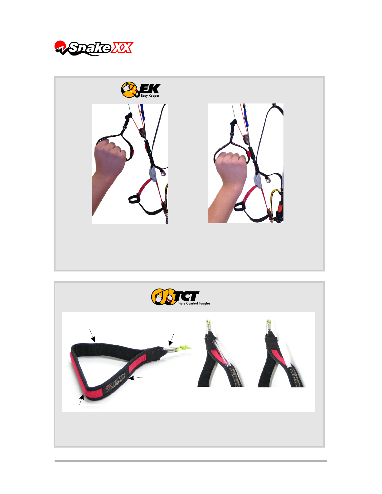
■ soft neoprene cover TCT,
■ EK (Easy Keeper) system – see further pages
9
Page 10

3. FLIGHT OPERATION
3.1 STEERING SYSTEM
Steering system consist of following parts:
1. 2D - multifunctional brake system (regular steering handles) – more details
on page 22;
2. TCL (Tip Control Line);
3. TST (Tip Steering Toggle) - additional mini toggles connected to TCL line,
for stabilo steering;
4. TEA (Torque Effect Adjuster) - in this case it’s a TCL line going through a
cleat, with a knot near the TST handle. For correct system operation the
exact position of the blocking knot must be adjusted, depending on the
torque;
5. traditional trimmers;
6. traditional speed system;
7. PA - Power Attack System.
Some of those part can act much the same way as ALC and TST systems
known from our other designs:
ALC - an outer 2D line fixed to the steering handle – you can use it alone, by
grabbing just this line above the handle (the handle itself can stay in hand,
can be fixed at docking station or even hang free)
TST - it is a TCL line fitted with a TST (Tip steering toggle), running from the
riser to according steering line towards the wing tip. You can use it for
steering by grabbing the line and pulling it outside, or just using the TST
handle.
Both the TST and entire TCL line can be dismantled for some of the slalom
tasks where it will remain practically unused, but may require some additional
attention.
Steering lines, pulleys and speed system adjustment
There are as many as three positions for the pulleys provided (picture on next
page).
Originally it is mounted on the risers in the middle position.
On the main steering lines there are points marked for fixing the brake
handles corresponding to the middle position of the pulley. Position of the
handles should be adjusted according to your pulley setting.
In practice moving the pulley from the middle (2) to highest position (1) does
not require any adjustment of the steering lines. Moving the pulleys to the
lowest position (3) will definitely require lengthening of the steering lines by
distance between positions (2) and (3).
10
Page 11
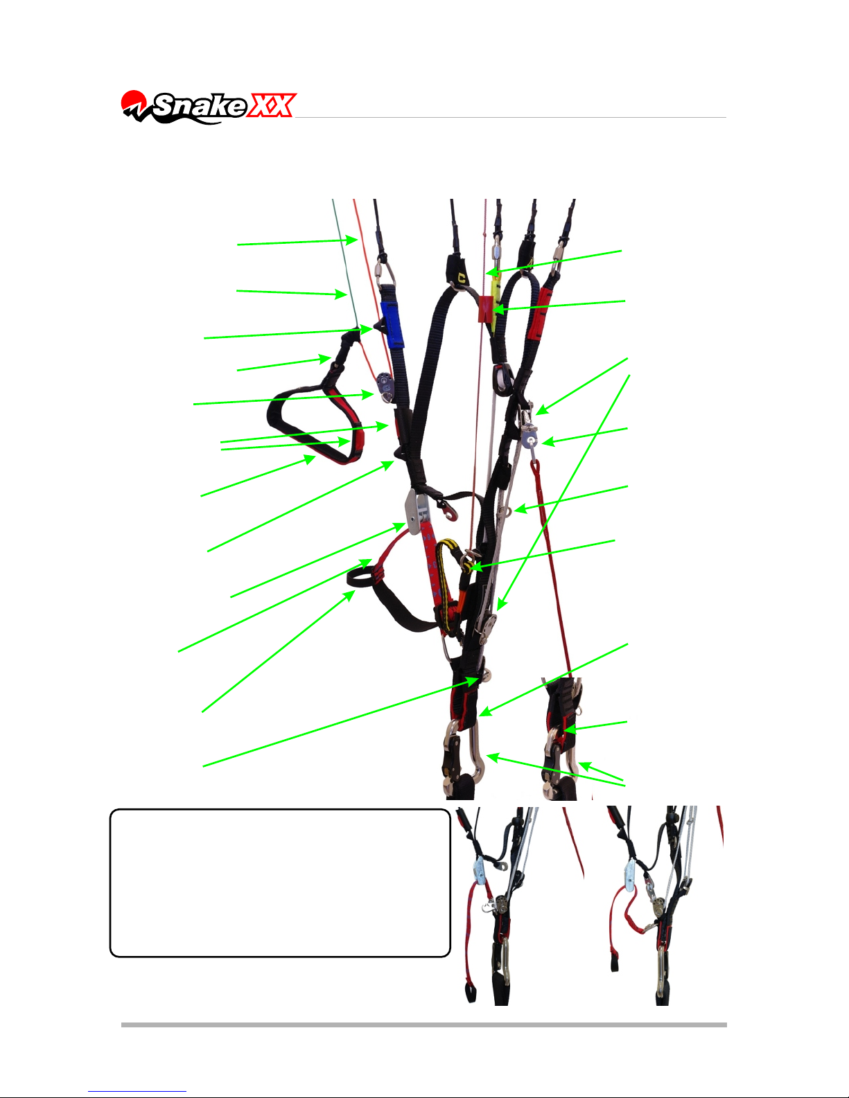
11
Risers in lower hangpoint configuration (pulley in the middle)
The PA system combines speed system
with trimmers, resulting in automatic,
smooth trimmer release on pressing the
speedbar. In order to activate the system,
you have to connect Power Attack hooks to
the trimmer and accordingly release
trimmer tape, restricting its movement.
trimmer buckle
pulley position (1)
trimmer
strap
inner 2D line
swivel
trimmer
handle
speed
system
pulleys
TEA lock
steering handle
Easy Keeper
magnets
pulley position (2)
pulley position (3)
PA system pulley
carabiner
speed
system
hooks
outer 2D line
speed
system
stop
higher point
for carabiner
lower point
for carabiner
TCL line
D
A
B
C
A'
TST handle
Page 12
12
Easy Keeper
Easy Keeper is our indigenous way to hold the brake handles at the risers by
strong neodymium magnets. It keeps the handles firmly at the risers, while both
attaching and releasing goes smoothly and easily. The system allows for easy
placing the brake handles on risers when they are not used in flight, thus
minimalizing danger of getting them into running propeller.
Triple Comfort Toggle
Addressing different needs of our clients we have created a TCT system - Triple
Comfort Toggle, making it possible to have your brake handles in rigid, half-rigid
or soft configuration without need to purchase additional handles.
Swivel protects
the steering line
against twisting
Neodymium magnet of the
Easy Keeper
exchangeable insert
slit of the rod
half-rigid
PVC tube
rigid plastic rod
The most soft handle is obtained when no
insertion is used.
Page 13
13
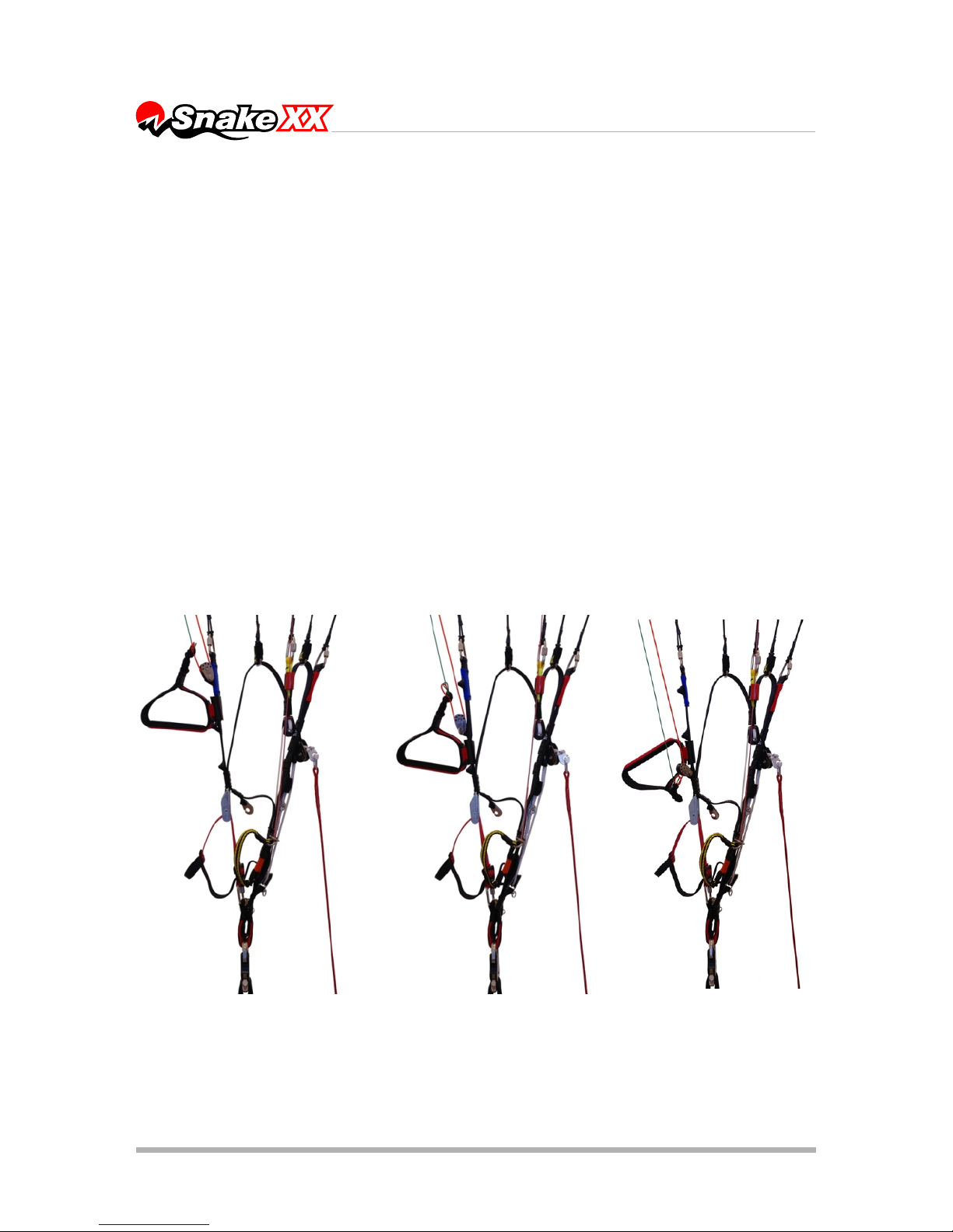
With all these changes it is possible to adjust placement of the Easy Keeper
magnets too. With highest position of the pulley, the magnet is at its highest
too, and with lower pulley positions the magnet is mounted lower position as
shown on the picture.
The length of the steering lines must to be adjusted so that at maximum
speed configuration (opened trimmers and full speeed bar) the brakes are
loose and do not pull the trailing edge.
Progression of the steering lines, i.e. difference in length between the central
steering line (going through the pulley) and the outer one (green) is set as
standard and some pilots can regard it as not aggressive enough. You can
adjust it to your own preferences, but please observe +/- 5 cm range and
safety rules mentioned above.
Before you will take on powered flight it is recommended to try the setup out.
Hang up the entire PPG unit with ropes, sit in the harness and have
someone pull up the risers. You must make sure that in flight you will always
Pulley in second (highest)
position; EK magnet placed
above the middle pulley
position
Pulley in middle position; EK
magnet placed above the
trimmer buckle
Pulley in first (lowest)
position; EK magnet placed
above the trimmer buckle
Page 14

14
be able to reach the brake handles, even if the airflow blows them away.
Being suspended in this way you have a perfect opportunity to adjust the
speed system too. The speedbar should not be pulling pull its lines nor risers
when not applied. Neither should it be too loose, for it could catch the
propeller then.
An additional way to check the whole configuration out is to visit the take-off
site in steady winds of 3-4 m/s. With the engine off, inflate the wing and take
it up over your head. When it stabilises, check that the brakes are completely
loose and do not affect the trailing edge. There should be a spare inch or so
before they activate.
Remember that it is always safer to set the margin of play too big than too
small. And, most importantly, the setting must always be symmetrical.
3.2 BEFORE YOU FLY
Powered flight
NOTE: Prior to each start a thorough check of the canopy, harness and
paramotor is necessary.
Correct matching of the canopy and paramotor belongs to the pilot. Dudek
Paragliders cannot take responsibility for all possible combinations, but we
are always there to help you – just contact us.
First flights
In order to get familiar with your wing we recommend flying with closed
trimmers first (or slightly opened, up to 3 cm), because in this configuration
Snake XX behaves more like a classic wing. For the starters it’s strongly
recommended to inactivate the Power Attack system. In order to do that you
have to unhook PA and the trimmers.
Once you feel confident with your wing, you can start experimenting with
faster trim settings and speed system. Learn to use all of the additional
speed and dynamics of the Snake XX.
3.3 TAKE-OFF
Classic launch with no wind
Even when it seems that there is no wind at all, it is rarely so. Therefore
always be careful in determining the conditions, since in PPG flying it is most
important that the launch and initial climb are performed with a head wind
(the danger of losing your airspeed while steep crossing of the wind gradient
is greatly reduced then). Special attention must be paid to trees, power lines
and other obstacles, including the possibility of emerging rotors.
Page 15

Paraglider preparation
Lay out the paraglider downwind of the power unit, with all suspension lines
taut and pointing toward center of the power unit. The risers are to be laid on
the ground. Set the trimmers as completely closed (0) or slightly opened up to
3 cm, depending on your preferences and weight (the scale is marked every 3
cm). In stronger conditions faster settings can be advised. Make sure that you
warm up the engine while standing windward of the wing. Stop the engine
before clipping in the risers.
Now have a quick check if:
■ the helmet is on and locked,
■ the risers are clipped in the carabiners,
■ the trimmers are properly set,
■ nothing will get in propeller's way,
■ speed system is running without problems,
■ steering lines and handles are free and not twisted,
■ the engine delivers full power,
■ take off area is clear of obstacles and free to use.
When you are sure everything is OK, you can clip in the wing. Move forward,
evenly pulling on the A risers. The canopy has practically no tendency to
overshoot, so it is hard to encounter. Instead the canopy kind of waits for you
to catch up with it.
From now on you should steer the paraglider facing forward, without looking
back over your shoulder (when the wing is low behind you, turning can cause
some lines to get in the propeller). Still, possible fall on your back and
damaging the propeller is dangerous (and costly!) so it should be avoided at
any price, even that of some damaged lines!
During launch, when you feel the strain on both risers to be equal, open up full
power and lean back to counter the engine thrust, so that it can push you
forward rather than towards the ground. The best option is not to use the
brakes, allowing the paraglider to rise as it was laid out. If it starts to swerve
from its course, just pull the opposite riser and run under the centre of the wing
while preserving starting direction. If the wind suddenly drops, give a stronger
pull on the risers.
If the paraglider falls to one side or back too far to be lifted again - kill the
engine, interrupt launch and check the conditions once again.
As the wing rises, the forces grow lighter and it should stabilise above your
head without overshooting. This is the best moment to check if it is inflated OK
and the lines are not tangled, but do so neither stopping nor turning. Once you
feel the forces on the risers decrease, run faster and let go of the risers. See if
there is already any opposition on the brakes and, if necessary, use them to
correct direction or to increase lift at take-off.
15
Page 16

Remember:
■ If the cage of your power unit is not stiff enough, the risers strained
during launch can deform it to the extent of collision with the propeller.
Before giving it full power, see that the cage does not catch any lines.
■ Any brake operation (or steering inputs in general) should be smooth
and gentle.
■ If the cage of your paramotor is too soft, risers strained during launch
can distort it so that the propeller will hit it. Before increasing power
make sure the cage is free of lines.
■ All steering inputs should be smooth and gradual
■ Do not try to take off until you have your wing overhead. Hitting power
before that can cause dangerous oscillations.
■ Do not sit in the harness until you are sure you are flying!
■ The faster the trim setting is, the more brake input is required to take off.
■ The lower the hangpoints of your power unit are, the easier is the
launch.
Reverse launch in strong wind
Reverse launch can be executed holding in one hand both A risers and one
brake, with throttle and the second brake in the other hand. With a decent
wind it is by far the best way. In weaker wind it is better to prepare a classic
launch, as running backwards with an engine on your back is not an easy
thing to do. It is reasonable not to pull the wing up until you are really
determined to launch, especially when it is clipped in.
Lay down the rolled paraglider with its trailing edge against the wind. Unfold
the wing enough to find the risers and check that no lines are looped over the
leading edge. Stretch the risers against the wind, separating the right and left
one.
We suggest that you lay the risers in the same way as you will be turning
during reverse launch, and place one riser over the other, with rear risers
upmost. It should be done this way because once you clip in, the cage of
your power unit will make turning on your own practically impossible (with the
canopy lying still).
Now run the pre-launch checklist.
After warming up the engine put the power unit on, turn to face the wing, go
to the risers and clip them in the appropriate carabiners.
Pulling on the front and rear risers open the cells. It is a good idea to pull up
the wing briefly in order to check that the lines are not tangled. Holding the
risers, brakes and throttle as described above, pull the front risers and inflate
the canopy. Snake XX comes up easily and sometimes it may require a dab
on the brakes to keep it over your head.
16
Page 17

Once the paraglider is stabilized and checked, you turn around, open the
throttle and take off. As with the classic launch you have to find such
combination of trimmers, brakes and throttle settings that will give you the
best speed and rate of climb.
Remember:
■ You are launching with your hands crossed. You have to really master
this technique before trying it with a running engine on your back.
■ Any brake operation (or steering inputs in general) should be smooth
and gentle.
■ Do not try to take off until you have your wing overhead. Hitting the
gas pedal before that can cause dangerous oscillations.
■ Do not sit in the harness until you are sure you are flying!
■ The faster the trim setting is, the stronger brake input is required to
take off.
■ When clipping in the crossed risers, you can find proper connection of
the speed system particularly hard. Be careful not to confuse the
risers!
Climbing
Once you took off safely, continue heading against the wind, using brakes
to correct rate of climb. Do not try to climb too steeply - attempts to increase
climb rate by pulling the brakes will have an adverse effect, as due to
additional drag the actual rate of climb will worsen and with the throttle fully
opened even a stall can happen.
In powered flight the Snake XX behaves more like an aeroplane than a
paraglider, and it is good idea to regard it as such. If there are no obstacles
present, it is by far safer (and more impressive for the spectators) to fly
level for a while after take-off and gain some speed before converting it to
height with a brief pull on the brakes. Another reason not to try climbing too
steeply is the risk connected with engine failure at low altitude. Even as
Snake XX in a steep climb does not stay behind as much as conventional
paragliders do, the low speed always can lead to a stall. Besides, at any
time you have to be prepared for engine malfunction, so it's better not to
take unnecessary chances and always fly with a safe margin of speed.
Depending on the power unit geometry, it is possible that after take-off you
will notice a propeller torque (turning moment). It will try to turn you around,
so be ready to counter-steer it with a brake or harness cross-bracing.
Risers of the Snake XX’a are equipped with two carabiner loops, higher and
lower one. Asymmetric use of those will help you fight the torque in case
when there is no cross-bracing present.
When climbing steeply with slow trim settings and high power output
beware of the possibility of stall.
17
Page 18

Due to typical PPG feature - considerable vertical distance between wing
chord and thrust axis - the range of safe power operation is closely related to
your skills and equipment.
Power-unit induced oscillations
Certain configurations of engine weight, output and propeller diameter can
cause serious oscillations, during which the pilot is being lifted to one side by
the torque effect, swings down due to his weight, then is lifted again and so
on.
To avoid this you can:
+change the throttle setting and/or
+adjust the cross bracing to counteract the torque, if there is one present
and/or
+use the TEA, pulling down the knot through the tube, simultaneously
blocking it in the slit and/or
+shift yourself to the other side of the harness and/or
+change the trimmer setting.
+while on the ground, attach the risers asymmetrically, using optional
carabiner loops.
The best method is to fasten opposite cross-bracing or apply some weightshift. Such oscillations usually occur at full power - the greater the engine
output and propeller diameter, the bigger the swings. In addition there are
often too late or wrong pilot reactions, increasing the problem instead of
solving it. In this case the safest way to deal with this question is to close the
throttle and release the brakes.
3.4 LEVEL FLIGHT
Once you have gained safe height after take-off and wish to
go for a route, you can turn onto right direction, fully open
the trimmers and let off the brakes. If the conditions are
turbulent, it can look foolhardy, but this is the essential
feature of the reflex profile - the faster
you fly, the safer your Snake XX is.
That's why it's really possible to
release the brakes and enjoy your
flight.
CAUTION: Some pilots with previous free-flying
experience may have a well-grounded habit of
keeping the brakes slightly applied at all times. Such
18
Page 19

technique, while quite reasonable on a free-flying wings as it allows for
quick pilot reactions and reduces sink, is not advisable on reflex-profile
paragliders. When you pull the brakes, the Snake XX profile loses its
reflex characteristics.
If you have a variometer or altimeter aboard – watch it. In level flight it is very
easy to start climbing unintentionally. The instruments will help you optimise
speed your and fuel economy.
Good knowledge of weather conditions (e.g. wind at different altitudes) and
smart use of thermals, convergence or other kinds of lift will help you greatly
reduce fuel consumption and increase flight range.
Trimmers and speed-system operation
The reflex wing airfoil enables the Snake XX pilot to use a wide range of
trimmers and speed-system action. You are free to experiment with all
possible settings, as long as you keep safe altitude.
Speed system of these risers is by default integrated with the Power Attack
system. If you intend to operate the trims independently of the Power Attack
system, you have to disengage the hooks joining the PA and the trimmers.
DO NOT USE THE SPEED SYSTEM WITH CLOSED TRIMMERS OR THE
POWER ATTACK SYSTEM BLOCKED! SUCH ACTION MAY CAUSE
VIOLENT COLLAPSES!!!
CORRECT SPEED SYSTEM OPERATION REQUIRES RELEASING
TRIMMERS BY AT LEAST 6 CM! (especially in lower part of the weight
range)
Trimmer and reflex profile
In the Snake XX, use of trimmer affects the aerofoil geometry. Closed
trimmers result in a profile featuring increased lift and reduced reflexivity (as it
is in Nucleon). Releasing the trimmers increases the reflex characteristics
proportionally.
To avoid stalls when braking with closed trimmers, their movement is
restricted by the tape sewing (Note: it is possible to push the sewn tape
through the buckle with both hands to replace it, but normal operation range
is restricted by said place!).
Speed system alters the attack angle. In contrast to the trimmers, it does not
affect the profile geometry. If the trimmers remain closed, speed system will
act more like in a classic paraglider, inclining the whole profile (with one
difference of not having a stay between A and B risers).
19
Page 20

Speed configurations
Basically we can discern three speed configurations, depending on trimmer
settings and speed-system operation:
a) Slow mode (trimmers closed): - steering with regular brakes
b) Accelerated mode (trimmers opened):
- steering with regular brakes possible (although that may require some
strength),
- it will be more effective to use just the outer (green) 2D steering line
connected to the brake handle, by grabbing it above the handle without letting
go of the toggle – thus increasing the progression,
- when the TST/TCL system is present you can leave your brakes at
corresponding docking stations and control the wing with TST handles.
c) Full speed mode (trimmers opened and speed-system engaged):
- pilot should never use neither main brakes, nor the outer (green) 2D steering
line,
- steering must be done with TST handle or TCL line only!
These are the basic guidelines only. As a whole, the combined 2D/TST/TCL
system is very versatile and every pilot will find his own way to use it. However,
we strongly collect at least several flight hours first, in order to get fully
acquainted with the Snake XX.
Flight - trimmers closed (slow mode): Steering is done with main brake
handles. You can pull them straight down along your body or sideways, away
from your body, thus differentiating the progression and bank angle.
1. Straight down along your body - bigger progression, sharper turns.
2. Away from your body - lesser progression, turns with less banking.
3. Combined technique - "inner" hand along the body, "outer" hand moves
away to keep central part of the canopy solid and stay ready for
necessary corrections.
Flight - trimmers off (accelerated mode): In general, steering is the same as
described above. However, a lot more force is needed, so you should consider
grabbing the outer steering line above the handle. In this way you will be
steering mainly via the outer part of steering system (much like ALC).
While on long routes, it is definitely recommended to steer using only the TST
handle or TCL (Tip Control Line).
Flight - trimmers off and speed-system engaged (full speed mode):
Due to relatively high aspect ratio of the Snake XX and consequent short
aerodynamic chord of the wingtips, steering the paraglider with main brake
handles at full speed configuration becomes impossible – all attempts to use
the main brakes will have no effect other than evoking collapses. As such, this
is not dangerous, it will even hardly alter the flight path (given that pilot won't
20
Page 21

21
Steering with a TST
(recommended in accelerated
mode, definitely required in full
speed mode):
When fully accelerated you should
be steering the canopy ONLY with
the TST handle or TCL line. Such
steering does not deform the reflex
aerofoil, guarantees safety and stays
effective.
Various steering modes with PA activated and deactivated
Steering with main brake toggles
only (slow or accelerated mode)
The toggle has different effects when
pulled down vs. away (details on next
page).
Main toggle + outer line (accelerated mode)
Variable steering progression depending on degree of operation.
Steering with outer line only (accelerated mode)
Main steering toggles can be docked on the magnets or let free.
Page 22

2D steering system – examples of operation
Below you can find basic modes of steering with 2D system. Demonstrated examples
are by far not a complete catalogue – there is a lot of interim configurations and only
the pilot will choose what kind of steering is the best in given situation.
2D steering is considerably different than the classic steering system. The possibilities
it offers are of special value for competition pilots. On one hand the 2D system offers
much more precise control of he canopy, but on the other it requires learning new
(different) reflexes and reactions. Pilot must spend some time exploring the system and
perfecting his own technique before flying 2D in demanding environment of the
competitions.
pulley
Conventional turn - pull down vertically on one toggle
1
ALC line
Conventional slow-down - pull down verticaly on both
toggles
2
Extreme slow-down with central part - pull inner lines
down
Deep turn - pull down the inner brake handle and
the outer toggle a little bit aside
6
4
Strong slow-down with central part - pull both toggles sidewise
Tight turn - pull down the outer ALC line
5
3
22
Page 23

be keeping the brakes down for long). However, this phenomenon is
undesirable, unpleasant and - most of all - not effective as a means of
directional corrections.
It follows that steering at full speed should be done only with the TST handle
or TCL line. Those systems do not distort the reflex profile, guaranteeing
safety and efficiency of operation.
Every pilot should find out for himself how much trimmer can be let out before
steering with main brakes at full speedbar becomes impossible, or alternatively - how much speedbar can be used with trimmers fully opened.
This will depend on a number of factors, including size of the canopy.
Finding that range is especially important in case of slalom competitions.
Flying slaloms with PA (Power Attack) system:
The PA system combines speed system with trimmers,
resulting in automatic, smooth trimmer release on
pressing the speedbar. In order to activate the system,
you have to connect Power Attack hooks to the trimmer
and accordingly release trimmer tape, restricting its
movement.
From this moment pilot can use entire range of the
aerofoil geometry, as well as attack angle (as far as the
trimmer tape has been released).
CAUTION
You have to remember that effects of the PA system can be pretty
dramatic, directly influencing your speed and sink rate. For the less
experienced pilots it can be a big surprise, being potentially dangerous.
In slalom flying common technique calls for flying at specific speedbar and
trimmer settings, enabling good canopy control without any collapses. When
exiting sharp turns the speedbar has to be pressed too, since not doing so will
result in rapid climb on dangerously high attack angle, with associated risk of
losing lift and entering stall or deep stall.
Multiple tests have shown that Power Atack system acts best with the trimmer
released by at least 6 cm and not more than 9 cm. Such settings allows to use
main steering handles for heading adjustment in accelerated flight, without
fear of tips collapsing.
Whenever you fly at high speed - be it on open trimmers or speedbar, or both
combined via PA system - smooth steering inputs are recommended. In
accelerated flight of the reflex canopy the last rows of suspension lines often
happen to be slack. Abrupt pulling on the steering handle causes immediate
23
Page 24

24
change of pressure & trimming of the aerofoil, resulting with rapid collapse.
At slower trim settings both the sink and steering forces are reduced, so that
effective thermalling becomes possible.
Please study pictures illustrating trimmers and speed-system operation on the
next page. They explain the influence of various settings on the profile shape.
Remember:
■ Trimmer setting is another thing to include in your pre-flight check list!
■ If the setting is not symmetrical, the paraglider will turn in flight. And if you
inadvertently release the trimmers, reflex profile of the Snake XX will keep
your wing level, so after hitting the gas you will descend with increased
speed instead of intended climbing.
Released trims without brakes
Typical setting for fast and safe flying. Center of
pressure of the aerofoil moves forward, practically
excluding collapses. Pitching moment induced by
the reflex aerofoil increases angle of attack.
Released trims with brakes applied
Even slight brakes application (especially on full
speed bar) shifts the center of pressure back, and
due to lack of reflex on trailing edge, pitching
moment now decreases angle of attack.
Additionally turbulence behind the wing occurs. In
some circumstances this can lead to a collapse.
Using the brakes can be sometimes necessary for
heading corrections, still you should keep your
brakes free when flying ahead, otherwise the reflex
feature doesn't work.
Closed trims
In this configuration brakes are the normal and
prescribed steering system. Slow trim is used for
launching & landing in nil wind, as well as
thermalling. Due to decreased speed of the
paraglider its steering characteristics remain similar
to classic profile paragliders (with increased tuck
resistance).
center of pressure
lift
speed
sink
pitching moment
Influence of classic steering on the reflex profile
Pilots used to classic paragliders tend to fly "active" style, with their brakes constantly tensioned.
Flying a reflex wing like that is ineffective and can possibly be dangerous.
Basic rule of reflex paramotoring says: the more turbulent it is, the more trims should be
released and classic steering should be limited, especially with speed system engaged.
In such moments paraglider is much more effectively steered by TST or ALC systems, designed
specifically for that reason.
Problem is illustrated by following drawings:
Page 25

25
Slow mode
Accelerated mode Full speed mode
Trimmers and speed-system influence on the aerofoil
Trimmers fully closed (0)
Speed-system inactive
Slowest speed,
Minimum sink.
Launch configuration
Trimmers fully opened
Speed-system inactive
(alternatively speed-system
engaged with closed trims)
Increased speed
Trimmers fully opened
Speed system engaged
Maximum speed
C
D
C
DBD A
C
A' B AA'B AA'
risers neutral:
A - 505
A’ - 505
B - 505
C - 457,5
D - 410
Trimmer:
A - 505
A’ - 505
B - 505
C - 532,5
D - 560
Trimmer + Speed:
A - 290
A’ - 340
B - 390
C - 475
D - 560
Speed:
A - 290
A’ - 340
B - 390
C - 400
D - 410
length of the risers (with maillons)
- length tolerance +/- 5mm
length of the risers (with maillons)
- length tolerance +/- 5mm
length of the risers (with maillons)
- length tolerance +/- 5mm
Page 26

3.5 LANDING
In paramotor flying there are two kinds of landing: with and without power.
Power off landing
At an altitude of 50 metres switch off the engine and glide as you would on a
conventional paraglider. It reduces the chances of damaging the propeller on
landing, but on the other hand there is only one attempt possible - so it has to
be done right!
Set the trimmers as fully closed (0) or slightly released (2 to 3 cm), depending
on individual preferences and weight of the pilot (same position as you would
for launching).
Since wing loading of the Snake XX is usually higher than of our other
paragliders, landing with slowed-down canopy with little speed should be
definitely avoided. In contrast, a full-speed landing with flare is recommended.
Snake XX is very efficient at converting airspeed for lift, so you can glide a long
way slowing down with gradual increase on the brakes. Finally the level flight
is stopped and soft touch-down ensues.
Powered landing
Make a flat approach with the engine idling, then level out and lose the speed
before final flare. Immediately after touchdown switch off the engine.
The main advantage of this procedure is of course possibility of repeated
approach if anything goes wrong. Still, if you forget to switch off the ignition
before the wing falls down, there is considerable risk of damaging propeller,
catching lines in it or even suffering injuries connected with falling on your
running engine.
Remember:
■ Whenever possible, get to know the landing field before taking off.
■ Check the wind direction before planning the approach.
■ Landing with power off requires much less space.
■ In case of any doubt, practice the landing until you feel totally safe.
3.6 GOLDEN RULES
■ Never place the power unit downwind of the paraglider.
■ Check, double check and then check once again if there is no fuel
leakage.
■ Do you have enough fuel for the flight? It is always better to have too
much than too little!
■ Check if there is nothing loose in the harness, that could possibly contact
the propeller in flight.
■ Whenever you encounter a problem, fix it AT ONCE however small it is!
■ Always put on and lock the helmet before getting in the harness.
26
Page 27

■ Before each launch run a full pre-flight inspection.
■ After landing, control the wing facing the direction of flight, as on turning
you always risk getting lines in the propeller. Turn only if there is danger of
falling on your back.
■ Don't ask for trouble - do not fly over water, between trees or power lines
and other places where engine failure will leave you helpless.
■ Mind the turbulence caused by other gliders or even by yourself, especially
when flying low.
■ It is not reasonable to let go of the brakes below 100 meters, because a
possible power unit malfunction may require immediate attention.
■ In general never trust your engine, as it can stop at any moment. Always fly
as if it's exactly what it's going to do.
■ Unless it is absolutely necessary (e.g. collision avoidance), do not execute
tight turns against the torque direction. Especially when climbing you can
easily enter a stall and consequent negative spin.
■ Do not fly with tail wind at low altitudes, as it pretty much narrows your
options!
■ Do not wait for the problem to grow - any change of engine sound or a
vibration can indicate troubles. You'll never know until you land and check it
out!
■ Be certain of your navigation
■ Remember that not everyone is fond of your engine noise. Do not scare
the animals.
3.7 FREE FLYING (NO PARAMOTOR)
Even as the Snake XX was designed as a fast PPG paraglider, it displays
surprisingly good behaviour as a classic paraglider and can be used as such
without any modifications.
It is forbidden to use the PA system while free-flying. If you plan on such flights,
you have to deactivate it. In order to do that, unhook PA and the trimmers.
The main difference between Snake XX and other paragliders is that due to
increased resistance to collapses (during launch as well as the flight) and wide
range of operational speeds it can be safely flown in stronger conditions too. In
general the faster you fly, the safer your paraglider is.
3.7.1 Take-off
In case of forward launch we recommend that after spreading the canopy all
lines be taut. Snake XX is launched A risers only. The optimal setting of the
trimmers is completely closed (slow), in case of strong wind they can be
released a bit. Now move forward, evenly pulling on both A risers. The paraglider
practically does not overshoot, so you will rarely encounter frontstalls (quite
often otherwise). Instead the canopy kind of waits for you to catch up with it.
27
Page 28

Reverse launch – we recommend the trimmers to be set as described above.
Due to no overshooting tendency the launch is easy, requiring only minimal
brake application before turning. Reverse launches can be executed even with
wind as weak as 1,5 m/s.
IMPORTANT!
Always during launch you have to pull your wing over your head. The
reflex aerofoil used in Snake XX has inherent tendency to increase the
angle of attack, so the paraglider can stay behind the pilot if he will not
careful at this point.
3.7.2 Flight
Snake XX's enlarged speed range may initially demand some attention.
However, once you have mastered these additional aspects, flying will become
pure pleasure. Good handling will let you make the best use of thermals, and
increased speed on glides means that your presence in sinking air will be
shorter.
To avoid stalls when braking with closed trimmers, their movement is restricted
by the tape sewing (Note: it is possible to push the sewn tape through the
buckle with both hands to replace it, but normal operation range is restricted by
said place!).
When the trims are fully opened the wing becomes faster and stiffer, increasing
its stability even more. The brake forces grow too, as well as the distance to
the stall point. The radius and bank angle in turns increase proportionately to
the growing brake forces.
When flying at full speed (trimmers opened / trimmers opened and speedbar
pushed), in rough air, it is highly recommended to steer the paraglider using
alternative steering methods like TST/TCL.
With increasing speed an effect of „inverting” the profile when trailing edge is
being pulled down emerges. That effect can cause dynamic collapses,
especially at full speed.
Speed system operation
Full application of the speed system increases flight speed by some 30%. In
contrast to most paragliders it does not decrease wing stability, in fact the
Snake XX seems to counter the turbulences even better. Still, if you meet
some serious trouble, it is advisable to release the speedbar. With application
of the speed system the brake forces grow, while brake effectiveness
decreases considerably.
At maximum speedbar and fully opened trims we strongly recommend
steering with TCL system. Turns executed in this way will be slightly wider,
but strength needed to initiate the turn will be smaller and there will be no
decrease in speed.
28
Page 29

It is recommended to use the speedsystem with trimmers opened
completely of by half. Using the speedsystem with closed trimmers can
result in a frontal collapse (especially in lower part of the weight range).
3.7.3 Landing
With closed trimmers (slow mode) Snake XX lands like any other paraglider.
The brake forces, initially low, are growing proportionally through entire range,
giving ample warnings before possible stalling. Nevertheless, you should
always be careful when flying very slow, until fully familiar with brake operation.
When landing with trims set fast (above "0" point), bleeding off speed can
require more space than usual. The paraglider has lots of kinetic energy and
careless application of brakes may even cause the wing to climb.
Most pilots get to know the wing relatively fast and quickly gain enough trust to
fly it in stronger conditions than they ever did. Still, you should always be
careful when flying low. Remember that Snake XX flies faster than ordinary
paragliders and sometimes it can be of importance (e.g. landing on a slope).
After landing in strong wind the paraglider can be safely put down with B risers,
or with a strong pull on the rear D risers.
3.7.4 Winching
Snake XX was not designed for winching. The reflex aerofoil used in this
paraglider has inherent tendency to increase the angle of attack. While in
normal flight such a disposition makes it safer, it can be dangerous during
winch start. Nevertheless, a lot of successful winches on have been made.
To sum it up: winching can be done, but proper attention must be paid.
3.8 QUICK DESCENT METHODS
3.8.1 Big Ears
In order to get the Big Ears you have to pull down the outer lines of the A'
risers (distinguished by neoprene sheath) by some 20-50 cm. While inducing
big ears you should never let the brakes out of your hands. After tucking the
tips in, paraglider will continue to fly straight with increased sink rate (up to 5
m/s). You can steer the wing pretty efficiently by weight-shifting.
After releasing lines, the paraglider will usually open up on its own or you can
assist it with a long stroke of the brakes.
For the sake of safety (the possibility of a parachutal stall) it is reasonable to
engage speed system after pulling big ears in order to lessen the angle of
attack of the wing centre. Executing big ears with opened trimmers is very
difficult due to reflex profile stabilisation.
CAUTION: See the PARACHUTAL STALL chapter.
29
Page 30

Never try to pull big ears during powered climb, as the increased drag
can cause excessive angle of attack and a parachutal stall.
Besides, pulling the ears while climbing is pointless anyway.
3.8.2 Spiral dive
Snake XX is a very agile paraglider, so entering spiral dive happens very
quickly and can be surprising for the less experienced pilots.
A spiral dive is characterised by reaching the highest sink rates possible.
Significant G-forces, however, make it difficult to sustain for long, as it will
place high loads on both pilot and glider to degree of losing consciousness by
the latter. Never do this manoeuvre in turbulence or at too high bank angles.
Control the dive and do not exceed 16 m/s sink. If the dive is not stopping after
releasing the brake, assist the paraglider with the outer one.
NEVER DO BIG EARS IN A SPIRAL! In this manoeuvre smaller number of
lines is carrying an excessive load multiplied by centrifugal force, what
can lead to damage of the lines or even the paraglider itself (load of a
single line can be much higher than tested in certification trials (i.e. 8G).
3.8.3 B-STALL
B-stall can be executed only with fully closed trimmers (i.e. pos. ‘0’).
To enter a B-stall, simultaneously pull down both B-risers (yellow tape) by 10 –
15 cm. The canopy will collapse across the entire span along its B-row, the
airflow over top surface will break and projected canopy surface will be
decreased. Forward movement will be almost completely stopped.
Further pulling B-risers is not advised, as tests have shown it to increase wing
instability. If the canopy forms a horseshoe with both wingtips in front of the
pilot, gently apply both brakes to recover.
To exit a B-stall, the risers should be released in a smooth and decisive
manner.
On quick and symmetrical releasing B-lines the airflow will be reinstated and
the wing will surge forward, returning to normal flight. In contrast to standard
paragliders, in case of Snake XX there is no need to counter this surge with
brakes - yet another asset of the reflex profile!
CAUTION: See the PARACHUTAL STALL chapter. All rapid descent
techniques should be practiced in smooth air and with sufficient altitude
only ! Full stalls and spins are to be avoided as recovery procedures,
since irrespective of paraglider type they may have dangerous
consequences!
BY FAR THE BEST TECHNIQUE IS SAFE AND CORRECT FLYING, SO
THAT YOU WILL NEVER NEED TO DESCEND RAPIDLY!
30
Page 31

3.9 EXTREME SITUATIONS
CAUTION: Due to high resistance of the Snake XX against both side and
front collapses, we strongly recommend not to provoke such situations
during safety trainings. Inducing collapses can be very hard to
impossible in standard way, while unconventional attempts can result in
extremely violent and dynamic behaviour.
PROVOKING EXTREME SITUATIONS SHOULD TAKE PLACE ONLY
DURING SAFETY TRAININGS UNDER SUPERVISION OF A QUALIFIED
INSTRUCTOR!
WHILE UNDER EXTREME CIRCUMSTANCES THERE IS HIGH
PROBABILITY OF TOO STRONG OR TOO HASTY STEERING INPUTS.
THAT'S WHY YOU SHOULD ALWAYS EMPLOY GOOD JUDGMENT, STAY
CALM AND TAKE MEASURED ACTIONS!
Since all actions required to exit or prevent dangerous situations are
typical and pilots flying Snake XX should already have proper
experience, we are going to describe only the characteristic features of
the Snake XX. Description of standard methods dealing with extreme
situations can be found in textbooks.
3.9.1 Side collapse
When the trimmers are fully opened or the speed system is engaged,
collapses practically do not occur and can be induced only by a very strong
turbulence.
Still, if it happens, a little counter-steering is enough to keep the canopy on
course. Under normal conditions with collapses up to 50% of the wingspan,
Snake XX will reinflate instantly and spontaneously. If not, you should aid this
process by application of brake on the collapsed side.
3.9.2 Symmetric collapse (frontstall)
The reflex profile of the Snake XX makes it practically impossible, especially
at higher speeds.
During tests we succeeded in creating this situation only with fully closed
trimmers and using special measures. Such forced collapses can lead to
extremely deep collapses, so recovery will require decisive pilot action (short
and equal application of both brakes).
3.9.3 Full stall and negative spin
May happen only as a result of serious neglect or intentional action of the
pilot. You have to be careful when flying at low speeds until fully familiar with
brake operation.
Wing recovers spontaneously in initial phase of stall, otherwise use standard
procedures.
31
Page 32

3.9.4 Deep stall
Under normal conditions does not occur. If you want to prevent it happen at
all, simply stick to a couple of rules:
■ after B-stall, release the risers quickly and evenly. Don't be afraid -
Snake XX does not jump forward excessively.
■ after big ears execution, engage the speed system. This will increase
both the sink rate and safety margin, as big ears constitute an effective
aerodynamic brake with significant loss speed.
Nevertheless, if such a parachutal stall happens e.g. due to strong turbulence,
simply apply some pressure on speed bar and/or push the A risers forward.
You can release the trims too.
3.9.5 Line over (cravatte)
Snake XX is a modern wing which, in order to decrease drag, has fewer
suspension lines and greater distances in between. Therefore it's always
possible that after a tuck one of the stabilisers may tangle in the lines. Usually
a couple of pulls with a brake settles the matter. If it's not enough, try to
untangle it with big ears or a stronger pull on the risers.
In case of any doubts you should seriously consider a rescue chute. It is there
as a normal equipment part, not just an ornament.
3.9.6 Emergency steering
In case of any malfunction that renders normal steering impossible, you can
safely steer and land Snake XX using the D-risers (blue marking) or stabilo
lines.
4. PARAGLIDER CARE
Proper looking after your paraglider will prolong the life of your Snake
XX
4.1 STORAGE
Snake XX's design incorporates newest technologies, including nylon lines in
the leading edge. That's why the paraglider should be carefully packed, with
proper conditions ensured for transport and storage.
Basic rules to be followed when folding the canopy:
1. Fold it accordion-wise rib to rib (cell by cell). Do not fold it by halves,
placing the stabilizers at the centerline.
2. When a compact package is crated on the longest chord do not roll it, but
32
Page 33

fold three to four times, from trailing edge towards the leading one.
3. The leading edge reamins on top of folded canopy.
Store the paraglider in a dry place, away from chemicals and UV exposure.
Never pack or store the glider when wet.
Remember that the wing becomes damp also while lying on green grass in
direct sunlight.
A good precaution to avoid dampness and/or UV when you have to wait in a
start queue is to use quick-pack after rigging up.
Always dry the glider thoroughly before packing and/or storage. Never pack
you paraglider too tightly.
While drying, never expose your paraglider to direct sunlight operation.
Please note that with frequent kiting/groundhandling exercises your paraglider
will deteriorate faster due to its repeated rising, falling and being dragged on
the ground.
4.2 CLEANING
Clean the paraglider with water and a soft sponge. Do not use any chemicals
or alcohol, as these can permanently damage the fabric.
4.3 REPAIRS
Repairs should only be carried out by the manufacturer, authorised distributor
or authorised workshop. It is acceptable to fix minor cloth damage with selfadhesive patches included in the package.
4.4 DETERIORATION - A FEW TIPS
The paraglider is made mainly of nylon - a fabric which, like any other
synthetic material, deteriorates through excessive exposure to UV rays that
come with the sunlight.
Hence it is recommended to reduce UV exposure to a minimum by keeping
the paraglider packed away when not in use. Even when packed in a bag, it
should not remain in the sun for long.
Snake XX's suspension lines consist of Technora inner core and polyester
sheath. Submitting them to excessive loads in flight should be avoided, as it
can cause irreversible damage.
Keep the paraglider clean, since getting dust in the lines and fabric will reduce
their durability.
Be careful to keep snow, sand or stones from entering the cell openings: their
weight can slow or even stall the glider, while sharp edges can damage the
cloth.
33
Page 34

34
Prevent lines from catching anything, as they can overstretch or tear. Do not
step on the lines.
Uncontrolled strong wind takeoffs or landings can result in the leading edge of
the canopy hitting the ground hard, which may seriously damage the ribs,
sewing and surface material.
Knots can chafe suspension and/or brake lines.
Check line lengths after tree or water landings, as they can stretch or shrink.
Measurement should be taken at the manufacturer or authorised workshop.
After landing in water you should check the wing fabric as well, since the
wave forces can cause the fabric to distort in some areas.
When taking the wing out of the water, always do this by trailing edge, so that
water can flow out freely. After a sea landing, rinse the paraglider with fresh
water. Since salt crystals can weaken the suspension lines even after rinsing
in fresh water, you should replace the lines with new ones immediately after
contact with salt water.
Every second year Snake XX should undergo technical inspection by
the manufacturer or authorised distributor. Strength of the unsheathed
lines should be controlled after every 100 flight hours, after 200 hrs or
two years complete line set should be replaced.
Page 35

5. TECHNICAL DATA
35
Snake XX 15 16 18 20 22 28
DGAC DGAC DGAC DGAC DGAC DGAC
60 60 60 60 60 60
15,00 16,00 18,00 20,00 22,00 28,00
12,94 13,81 15,53 17,26 18,98 24,16
9,40 9,71 10,30 10,86 11,39 12,85
7,62 7,86 8,34 8,79 9,22 10,41
5,90
4,48
min = 1,3 + - 0,2
1966,00 2030,00 2154,00 2270,00 2381,00 2686,00
449,00 464,00 492,00 519,00 544,00 614,00
5,64 5,83 6,18 6,52 6,83 7,71
251,41 260,00 276,43 291,96 306,74 347,43
90 - 135 95 - 145 130 - 170 160 – 230
4,40 4,60 4,90 5,60 5,80 6,35
PASAMON - Bydgoszcz, Polska
Certification
Number of cells
Surface area (flat) [m2]
Surface area (projected) [m2]
Span (flat) [m]
Span (projected) [m]
Aspect Ratio (flat)
Aspect Ratio (projected)
Sink rate [m/s]
Speed [km/h] min = 30; trim = 46-60; max = 75 + - 5
Max. cord [mm]
Min. cord [mm]
Distance pilot to wing [m]
Total line lenght [m]
Weight range [kg] 110 - 150 120 - 160
Weight [kg]
Lines Edelrid A-8000U: 050; 090; 130 / Liros TSL: 090 & 140 & 190 & 280
Fabric Porcher Sport 38 g/m
2
Dominico tex 34 g/m
2
Porcher Sport Hard 40 g/m
2
SR Scrim, SR Laminate 180 g/m
2
Risers
Page 36

6. WARRANTY AND AEROCASCO
Purchase of a new paraglider is a serious expense for any pilot. That is why
we cover our paragliders with extensive warranties and optionally offer an
AeroCasco insurance against damage and repair costs.
WARRANTY
Dudek Paragliders guarantees free of charge repairs caused by the material
or production faults along following scheme:
For the free-flying paragliders warranty covers 36
months (3 years) or 300 flight hours (whichever
comes first). If the free-flying paraglider is used for
powered flights, every hour spent in the air should be
counted double (does not apply to dedicated PPG
canopies).
For the PPG paragliders warranty covers 24 months
(2 years)/200 flight hours (whichever comes first).
For the mountaineering (MPG) and speedflying wings
as well as school and profit users warranty covers 18
months (1.5 year)/150 flight hours (whichever comes
first).
WARRANTY DOES NOT COVER:
WARRANTY IS ONLY VALID IF:
■ fading or other colour changes of the canopy
■ damage caused by chemicals or salt water
■ damage caused by incorrect use
■ damage caused by emergency situations
■ damage resulting from accidents (airborne or not)
■ flight hours are correctly registered in logbook of the owner (and
possible earlier owners), distinctly marking PPG flights,
■ the paraglider is used in accordance with operating manual,
■ the purchaser has not carried out any repair by him/herself (excl. minor
repairs with self-adhesive patches),
■ the purchaser has not modified the paraglider in any way,
■ the canopy can be correctly identified with nameplate data,
36
Page 37

If you have bought your paraglider second-hand, ask its previous owner of
the paraglider for a logbook copy (it's total of flying hours since the date of
first purchase that counts most).
AEROCASCO
Normal warranty does not cover repairs of damages
caused by the user or a third party. Since costs of such
repairs can be considerable, Dudek Paragliders offers an
AeroCasco insurance. It covers a one-off repair of any
mechanical damages, no matter how big and whoever
inflicted them.
The only expenses of the purchaser is shipping and socalled share-of-cost amount.
AeroCasco can be purchased only for brand new paragliders (at the
paraglider purchase). Its cost is 50 euro.
NOTE: AeroCasco is not available for all paragliders (check this before
purchase). It can be obtained for privately used wings only.
AeroCasco applies only to damages which took place during take-off, flight
or landing. Obviously, all faults in the material and manufacturing flaws are
covered by normal warranty.
When handing the paraglider for the repair you have to attach a card
confirming its AeroCasco status. After the repair you will have to cover only
the share-of-cost value of 50 euro.
AeroCasco is valid for one repair only.
There is a possibility to extend AeroCasco for one more year. To do this you
have to send your paraglider for inspection not later than a year after the
date of purchase. Extension fee is 75 euro (incl. inspection). Remember to
attach the AeroCasco confirmation when shipping the paraglider. Note:
aditional inspection does not extend the full inspection validity.
AeroCasco does not apply to any of the following: theft, colour fading,
damage caused by incorrect storage or transport, damage caused by
chemicals, salt water and force majeure.
37
Page 38

7. WHAT HAVE YOU BOUGHT
The Dudek paraglider you've purchased should have the following items:
■ the paraglider itself (canopy, lines and risers),
■ transport bag (with compression strap),
■ MotoBag backpack with quickpack,
■ speed system with Easy Catch bar,
■ a windsock,
■ a pocket with paper work and repair wallet including:
4A piece of self-adhesive fabric (10 cm x 37.5 cm) for small repairs.
Note that even small tears located in vicinity of the stitches have to
be repaired by an authorised service,
4A looped and stitched suspension line longer than the longest used
in paraglider, which is to be used as a temporary replacement. Do
not cut it if you have to replace a shorter line, just tie it at the length
needed,
4A paraglider passport with entered date of purchase and valid
technical inspection (please check the serial number with the
sticker on the wing tip),
4The User Manual you are reading,
■ Small gifts.
38
Page 39

SUMMARY
If you will respect the rules of safe flying and proper glider care, you will
enjoy many years of pleasant airtime. Still, you must be aware of possible
dangers and face them wisely. You must accept the fact that all air sports are
potentially dangerous and your actual safety depends solely on you.
We insist that you fly safely, and this concerns both the weather choice and
safety margin during all manoeuvres.
FLYING THE PARAGLIDER IS ALWAYS YOUR OWN RESPONSIBILITY.
SEE YOU IN THE AIR!
8. RIGGING SCHEME
Rigging (suspension lines) scheme is on the next page, while tables of lines'
lengths are published on our website www.dudek.eu
Lengths are measured with a specialised, computer-operated device. All
lines are stretched with a 5 kg load before cutting. Thanks to
abovementioned device and proper procedures, final tolerance of line
lengths does not exceed +/- 10mm.
CAUTION!!! Distances given below are to be understood as distances
between connection points. When cutting a line for repair, 20 cm extra must
be added as at each end a 10 cm stitch is required to fix the loop. The only
exception is the main steering line (brmain), which is looped only at the
upper end, while there is 30 cm left on the lower end for fastening brake
handle (this means for this line extra 40 cm is needed).
39
Page 40

40
Page 41

V 28.05.20154
Dudek Paragliders
ul. Centralna 2U
86-031 Osielsko, Poland
tel. (+48) 52 324 17 40
export@dudek.eu
www.dudek.eu
MADE IN
EUROPE
 Loading...