

Page 1

Installation Guide
U-Track
Thank you for selecting a DuctSox System. This guide will be helpful for the installation of a U-Track
System. Sections of fabric will be labeled, assembled, bagged, and boxed for shipping. More
complicated systems will include a CAD detail of the system identifying what is in each package.
Overview
Inventory
The rst step on any installation project is to read through this guide thoroughly and review the
components that need to be installed. The best way to do this is to review the drawings of the project
while reading the guide, including the CAD detail if applicable.
Shipping/Receiving
In some cases the DuctSox support system is delivered to the job site ahead of the DuctSox fabric
sections. Depending on the size of a project or order, a DuctSox system will be shipped by common
courier in a single brown box or several boxes. Larger orders will be shipped in crates by a common
freight courier. Each DuctSox length should be packaged into individual plastic bags and labeled
according to size and number of pieces. Other markings or labeling may also be incorporated for
larger or more complicated systems. Be sure you have determined all boxes are accounted for.
Unpacking
Inspect shipment carefully and make sure all pieces are accounted for. Account for everything by
emptying the box and examining all contents. Note any missing or damaged pieces listed on the Bill of
Lading.
Labeling
Each DuctSox section will be marked with the size and section number either inside the belt of the
inlet or on a tag inside the DuctSox near the zipper. The marking shall be the diameter, section length
and total length. If custom labeling has been used, locate an identication sheet that will be included
with the delivery.
Equipment Required:
• Drill/driver and magnetic #2 Phillips driver bit
• Level
• #2 Phillips screwdriver
• Tape measure
• Marker or pencil
• Wrenches for cable-to-track connection (7/16” and 7/32” or pliers)
• Flat (standard) screwdriver
• Cable cutter
1
Installation Guide:
U-Track
Page 2
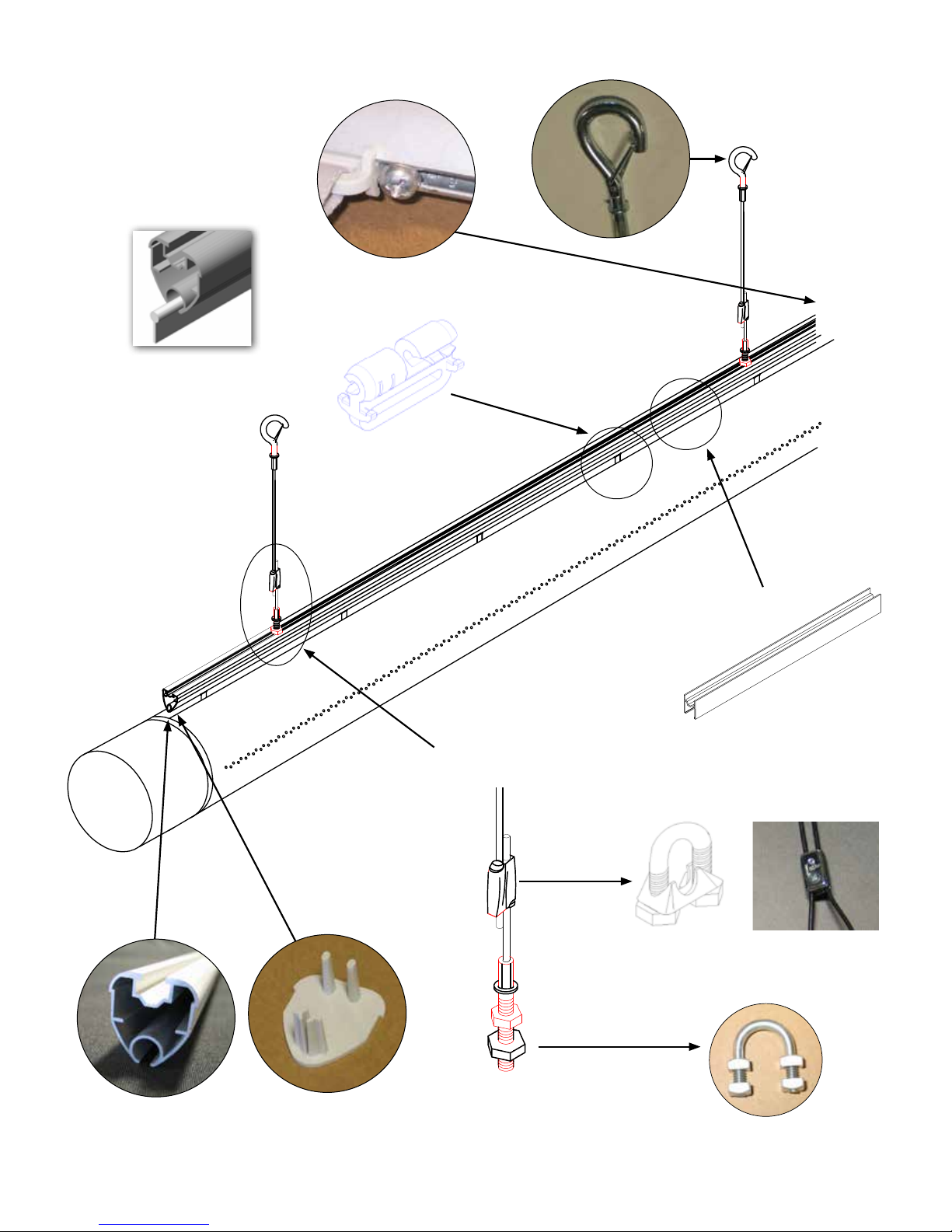
Component Details
Optional:
Cord-In Attachment
may be used as an
alternative to Gliders
Glider Attachment
Hook of Cable Support
Track Stop
Quick-Connection and
Stud Cable End
Cable Clamp for
U-Bolt option
U-Track
Coupler
Alternate clamp for
Pool applications
Aluminum
U-Track
U-Track Endcap
2
U-Bolt for
U-Bolt option
Installation Guide:
U-Track
Page 3
Installation Steps
1. Review materials in box, including the CAD drawing and installed location of the DuctSox
2. Prepare metal inlet collar for fabric connection
3. Mark placement of track. (1 Row, 2 Row, and 3 Row Style) Install track (with couplers and track supports
OR surface mount clips)
4. Install and assemble DuctSox components
5. Start up AHU
6. Balance airow
Step 1
Review materials in box, including the CAD drawing and installed location of the DuctSox. READ
INSTRUCTIONS THOROUGHLY BEFORE BEGINNING.
Step 2
Prepare metal inlet collar for fabric connection.
• Conrm inlet air supply location.
• Conrm inlet air supply size.
• DuctSox inlets are manufactured 1/2” (12mm) larger than
specied to t over metal inlet collar.
• Metal collar length should be 6”–10” (150 to 250cm) for
secure fabric attachment.
• Edge Guard (provided) should be installed on the edge of
the metal collar to reduce fabric wear from the metal edge.
6”–10”
(150 – 250cm)
Edge Guard
(Supplied)
Step 3
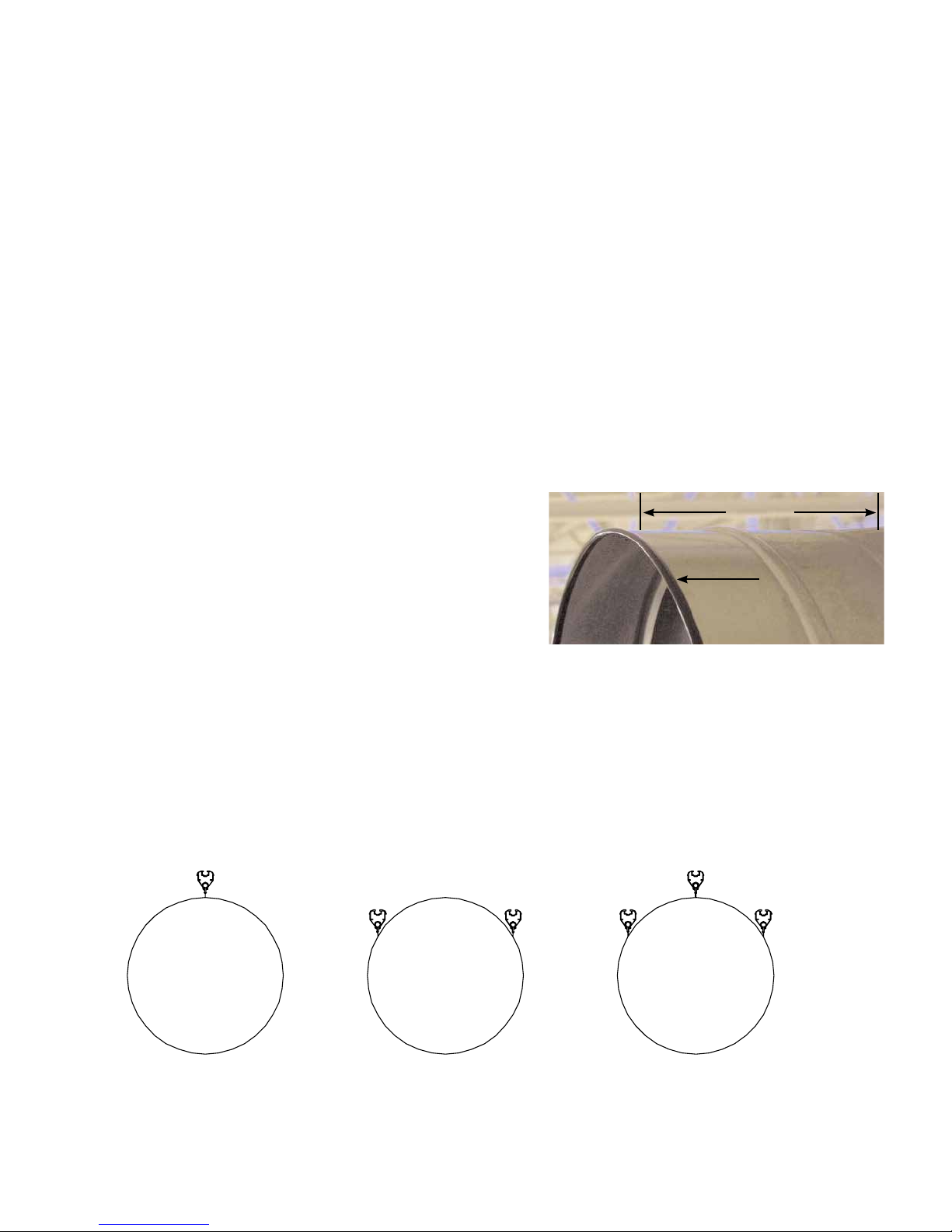
Mark Placement of Track. Step 3 is broken into three types of suspension points: 1 Row, 2 Row, and 3
Row. One job may use multiple styles.
Step 3 – 1 Row Style Step 3 – 2 Row Style Step 3 – 3 Row Style
10 and 2 O’clock 10, 2, and 12 O’clock
3
Installation Guide:
U-Track
Page 4
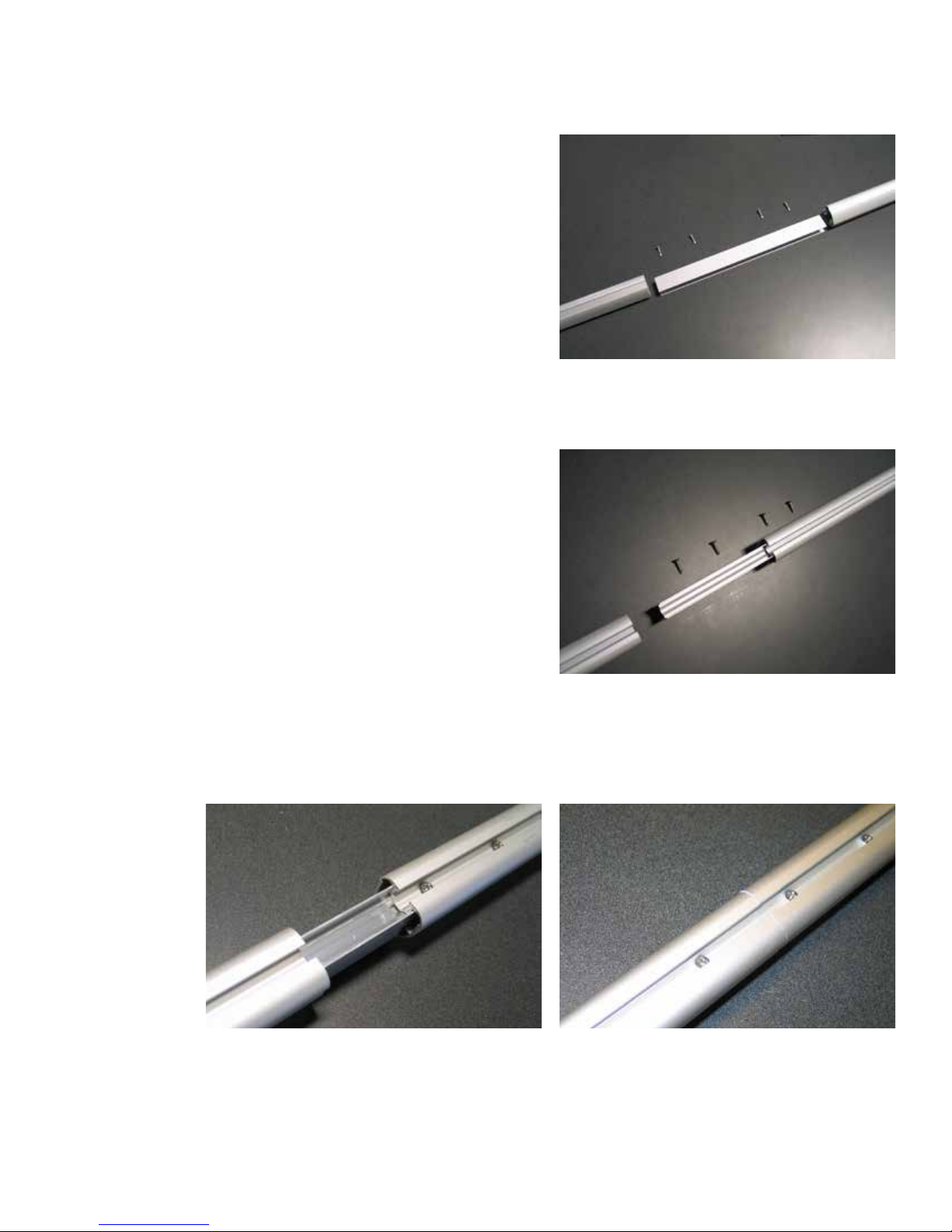
The following three details (Track and Internal Couplers, Track Supports, and End Caps) are used for
ALL styles.
Track and Internal Coupler
Track sections are shipped in 8 ft (2440mm) standard
lengths.
Coupler assembly consists of a 12” (305mm) long coupler
and 4 self-drilling screws as pictured.
Coupler is inserted into one track about 6” (150mm) and
secured with two screws. Screws are driven through the top
of the track to secure coupler and track in place. Note: Use
screws supplied.
Insert the rest of the coupler into the other track. Be sure to get each section of track as close together as
possible so that the coupler is not visible. Secure the coupler in the tracks with two screws for each track.
4
Installation Guide:
U-Track
Page 5
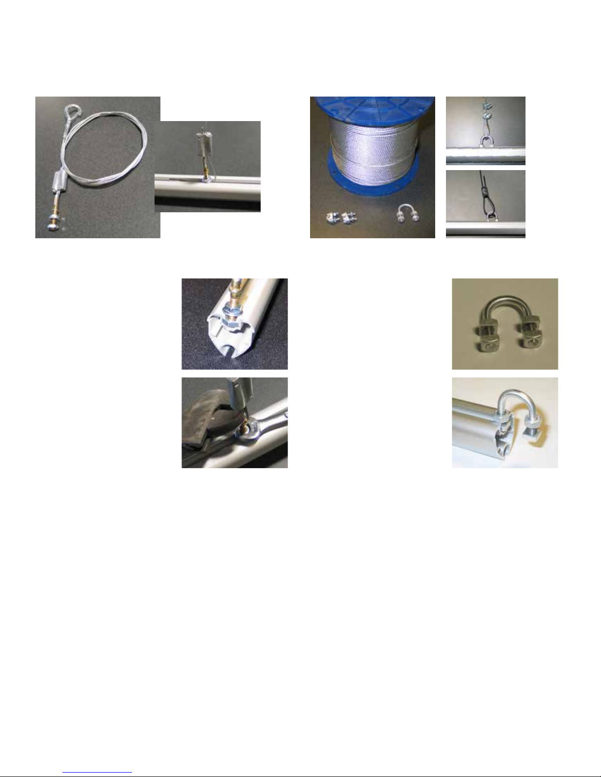
Track supports: Quick-connection or U-Bolt
The Track Supports are the main structural support between the U-track & DuctSox and the structure of
the building. A Quick-Connection Track Support OR a U-Bolt Track Support are the available options.
Standard
Pools
Quick-Connection Track Support Option U-Bolt Track Support Option OR Pool Applications
Hook end is attached
to structure above the
DuctSox. DO NOT loop
the hook back onto the
cable, this could cause
the hook to detach. Hook
must be hooked into part
of the building structure,
for example an eyebolt
attached to the ceiling. Nut
on the end of the stud is
permanently xed and is
not adjustable. This nut is
slid into the top channel
of the track. After stud
and cable are in their proper location the top nut
(7/16”wrench) on the stud must be tightened onto
the track while holding the stud with a pliers. After
adjusting the track height trim excess cable as
needed.
A roll of cable, U-bolts,
square nuts for U-bolts,
regular nuts for U-bolts
and cable clamps are
supplied. Length from the
ceiling support and the
top of the track needs to
be determined by installer.
A cable loop is created
at the top of the cable
length by a cable clamp.
Be sure the installed
cable does not contact
any sharp edges; for
example, loop the cable
through an eyebolt attached to the ceiling. Be sure
all of the threads of the square nuts are engaged
to the U-bolt. The square nuts on the end of the
U-bolt are slid into the top channel of the track.
After U-bolt and cable are in their proper location
the nuts (7/16”wrench) on the U-bolts must be
tightened onto the track. A cable loop is created at
the top of the track by the cable through the U-bolt
clamp. After adjusting the track height trim excess
cable as needed.
NOTE for both supports: Placing track at the proper elevation (this could be an angle for a sloped
ceiling) and straightness is critical for a good installation.
5
Installation Guide:
U-Track
Page 6
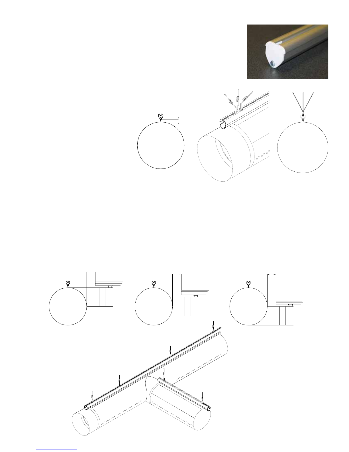
Endcap
A U-track Endcap gives the U-track a nice nished look on cut ends. Endcap
is friction-t and simply needs to be pressed into place. A sheet metal screw
should be used to hold the endcap in place.
Step 3 - 1 Row Style
Determine placement of track (both track path and elevation). The bottom
of the U-Track must be mounted 1.5” (38mm) for standard Glider and
Cord-In is 0.5” (13mm) above the
12:00 location of the DuctSox.
Track supports are spaced between
5 to 8 ft (1524 to 2440mm) apart
with a maximum of 8 ft (2440mm).
Additional Track Supports must
also be mounted at both ends of
continuous track runs for stabilization
(or as an alternative, the track can
be secured by mounting the ends
with threaded rod). The track support
cable will need to be mounted at
angles away from the sides of the track along with angled cables in-line with the track. See image above.
1.5” (38mm)
Standard
or
0.5” (13mm)
for Cord-In
T’s
There should be roughly 12” (305mm) from sidewall of DuctSox to the start of the branch track. Track too
close to the main run may cause premature failure due to abrasion from the track. Support around fabric
ttings may require additional track supports. NOTE: Offset distance of branch U-Track from main trunk is
approximately half of the main trunk diameter plus 12” (305mm).
12”
(305mm)
12”
(305mm)
12”
(305mm)
6
Installation Guide:
U-Track
Page 7
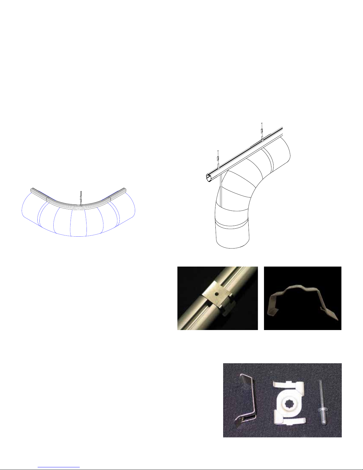
Elbows
Radius track is manufactured at the same radius of the DuctSox, this is typically 1.5 times the diameter of
the DuctSox. For example, a 24” diameter DuctSox would have a radius track with a radius of 36”.
(74” x 1.5 = 36”)
Install at least one Track Support per radius section; in the center if possible.
Coupler will not go into radius track the full 6” (and it shouldn’t). Coupler must only be inserted into radius
track 1.5”. This connection will only use one screw in the radius track portion. There will be 3” radius
couplers when splicing radius-to-radius connections.)
Radius track will only work with DuctSox that are installed in
a true horizontal plane (Figure A).
Vertical elbows are supported by D-ring straps rather than
radius track (Figure B).
Figure A Figure B
Surface Mount Hanging Option
U-Track in the 1-row style can be installed to a
ceiling surface by multiple options.
Surface Mount Clip: A specially designed clip that
snaps to the top of the U-Track. This clip can be
mounted straight to the ceiling. After mounting to
the ceiling the U-Track can be pushed up into the
clip and fastened in place. U-Track should be supported every 4 to 6 ft (1220 to 1830mm) when used in
the Surface Mount Hanging option.
Optional T-Bar Clip: A T-Bar clip is riveted (by installing contractor)
to the Surface Mount clip. The U-Track is snapped to the Surface
Mount clip and the bottom of the T-Bar ceiling support.
7
Installation Guide:
U-Track
Page 8
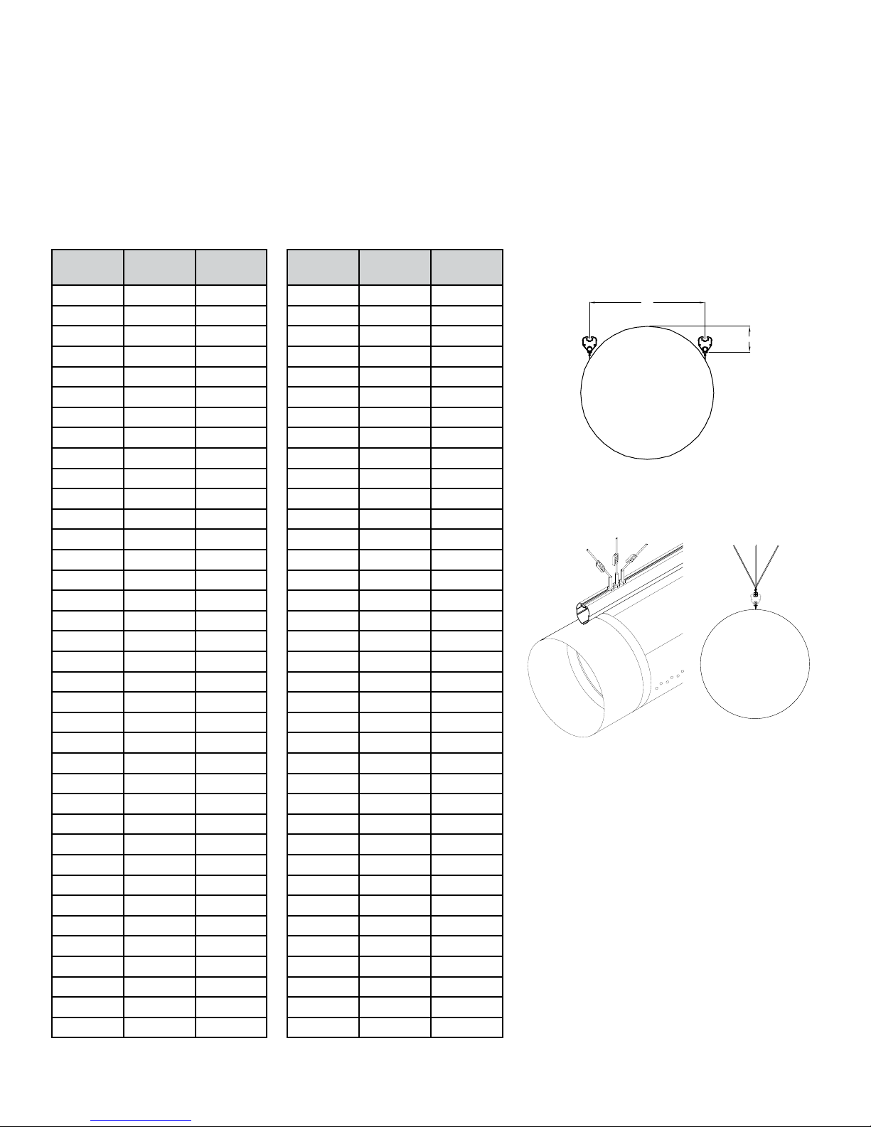
Step 3 – 2 Row Style
Determine placement of track (both track path and elevation). The bottom of the U-Track must be mounted
“A” inches apart and “B” inches below the 12:00 location of the DuctSox (match this up to the chart and
the drawing.) Track supports are spaced between 5 to 8 ft (1524 to 2440mm) apart with a maximum of 8
ft (2440mm). Additional Track Supports must also be mounted at both ends of continuous track runs for
stabilization (or as an alternative, the track can be secured by mounting the ends with threaded rod). The
track support cable will need to be mounted at angles away from the sides of the track along with angled
cables in-line with the track. See image below.
Diameter
(inches) A B
12 10.83 1.63
14 12.56 2.13
16 14.29 2.63
18 16.02 3.13
20 17.75 3.63
22 19.49 4.13
24 21.22 4.63
26 22.95 5.13
28 24.68 5.63
30 26.41 6.13
32 28.15 6.63
34 29.88 7.13
36 31. 61 7.63
38 33.34 8.13
40 35.07 8.63
42 36.81 9.13
44 38.54 9.63
46 40.27 10.13
48 42.00 10.63
50 43.73 11.13
52 45.47 11.63
54 47.20 12.13
56 48.93 12.63
58 50.66 13.13
60 52.39 13.63
62 54.13 14.13
64 55.86 14.63
66 57.59 15.13
68 59.32 15.63
70 61.05 16.13
72 62.79 16.63
74 64.52 17.1 3
76 66.25 17.63
78 67.98 18.13
80 69.72 18.63
82 71.45 19.13
84 73.18 19.63
Diameter
(mm) A B
305 275 41
356 319 54
406 363 67
457 407 79
508 451 92
559 495 105
610 539 117
660 583 130
711 627 143
762 671 156
813 715 168
864 759 181
914 803 194
965 8 47 206
1016 891 219
1067 935 232
1118 979 244
1168 1023 257
1219 1067 270
1270 1111 283
1321 1155 295
1372 1199 308
1422 1243 321
1473 1287 333
1524 1331 346
1575 1375 359
1626 1419 371
1676 1463 384
1727 1507 397
1778 1551 410
1829 1595 422
1880 1639 435
1930 1683 448
1981 1727 460
2032 1771 473
2083 1815 486
2134 1859 498
A
B
8
Installation Guide:
U-Track
Page 9
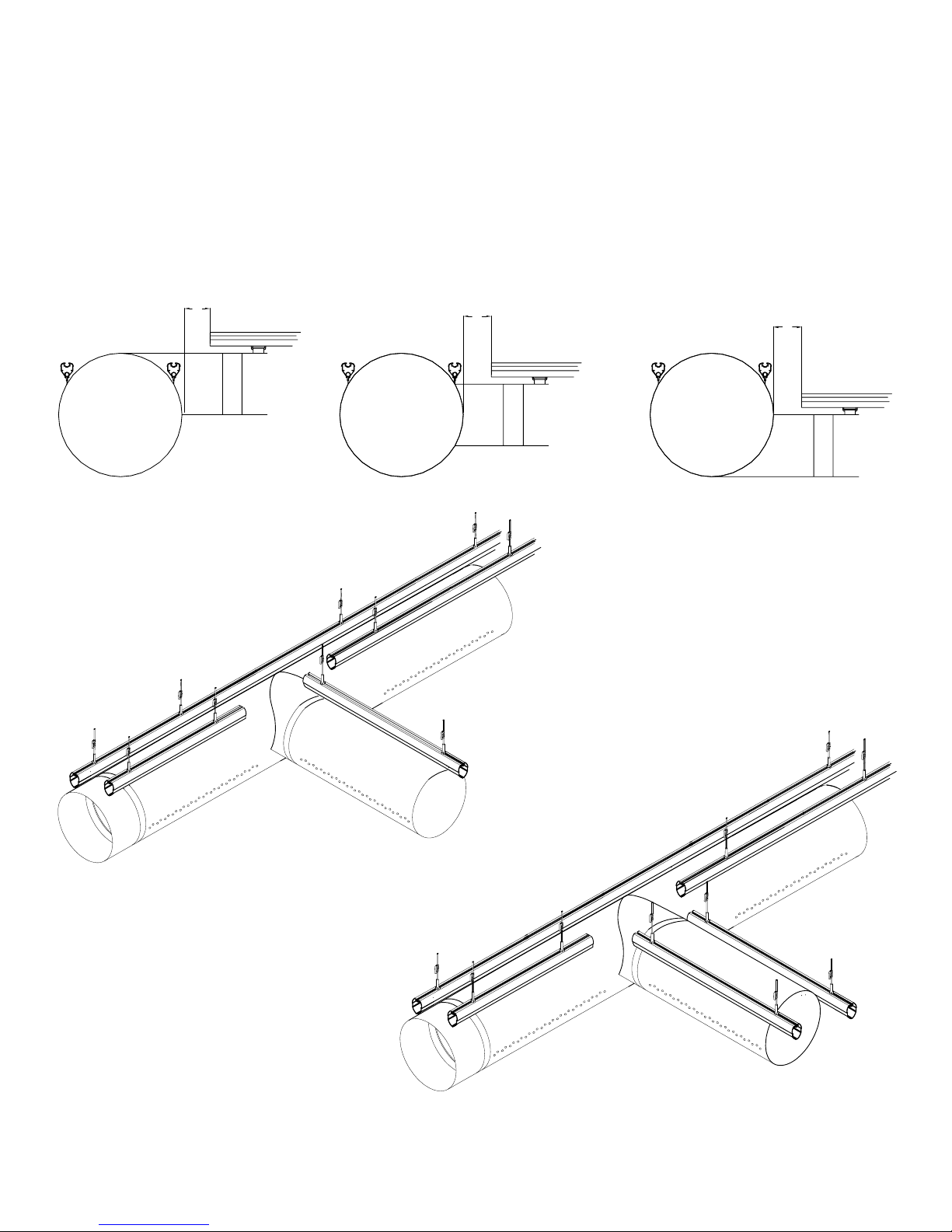
T’s
There should be roughly 12” (305mm) from sidewall of DuctSox to start of the branch track. Track too
close to the main run may cause premature failure due to abrasion from the track.
Support around fabric ttings may require additional track supports.
NOTE: Offset distance of branch U-Track from main trunk is approximately half of the main trunk diameter
plus 12” (305mm).
12”
(305mm)
12”
(305mm)
12”
(305mm)
9
Installation Guide:
U-Track
Page 10
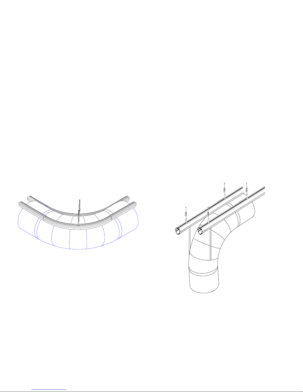
Elbows
Radius tracks are manufactured to match the radius of the DuctSox. This is typically 1.5 times the
diameter of the DuctSox. For example, the inside radius track of a 24” diameter DuctSox would have a
radius of 25.6”.
24” x 1.07 = 25.6
((24” x 1.5) - (24”/2 x .866) = 25.6”)
And the outside radius track of a 24” diameter DuctSox would have a radius of 46.4”.
24” x 1.93 = 46.4”
((24” x 1.5) + (24”/2 x .866) = 46.4”)
Install at least one support per radius section, in the center if possible.
Coupler will not go into radius track the full 6” (and it shouldn’t). Coupler must only be inserted into radius
track 1.5”( this connection will only use one screw in the radius track portion. There will be 3” radius
couplers when splicing radius-to-radius connections.)
Radius track will only work with DuctSox that are installed in a true horizontal plane (Figure A).
Vertical elbows are supported by D-ring straps rather than radius track (Figure B).
Figure A Figure B
10
Installation Guide:
U-Track
Page 11
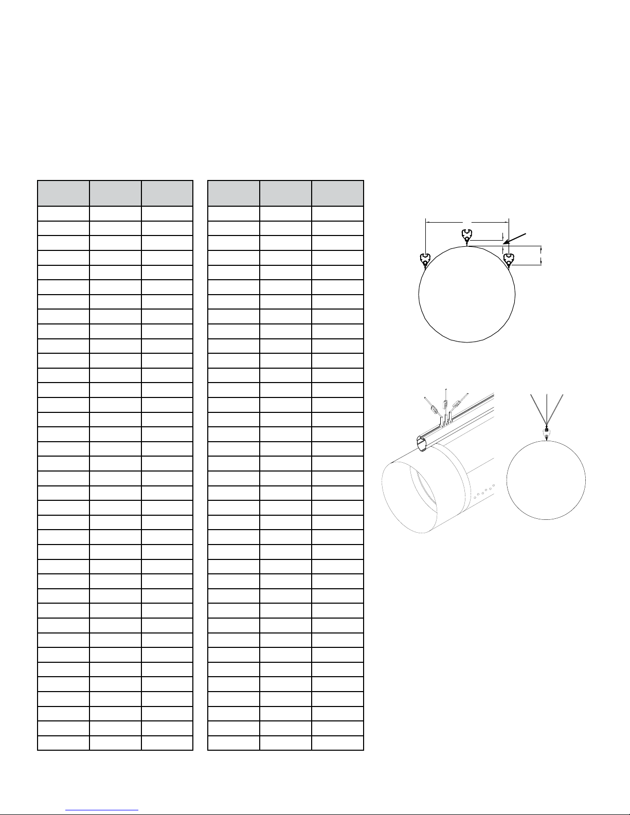
Step 3 – 3 Row Style (10, 2, and 12)
Determine placement of track (both track path and elevation). The bottom of the U-Track must be mounted
“A” inches apart and either “B” inches or 1.5” (38mm) below the 12:00 location of the DuctSox. Track
supports are spaced between 5 to 8 ft (1524 to 2440mm) apart with a maximum of 8 ft (2440mm).
Additional Track Supports must also be mounted at both ends of continuous track runs for stabilization (or
as an alternative, the track can be secured by mounting the ends with threaded rod). The track support
cable will need to be mounted at angles away from the sides of the track along with angled cables in-line
with the track. See image below.
Diameter
(inches) A B
12 10.83 1.63
14 12.56 2.13
16 14.29 2.63
18 16.02 3.13
20 17.75 3.63
22 19.49 4.13
24 21.22 4.63
26 22.95 5.13
28 24.68 5.63
30 26.41 6.13
32 28.15 6.63
34 29.88 7.13
36 31. 61 7.63
38 33.34 8.13
40 35.07 8.63
42 36.81 9.13
44 38.54 9.63
46 40.27 10.13
48 42.00 10.63
50 43.73 11.13
52 45.47 11.63
54 47.20 12.13
56 48.93 12.63
58 50.66 13.13
60 52.39 13.63
62 54.13 14.13
64 55.86 14.63
66 57.59 15.13
68 59.32 15.63
70 61.05 16.13
72 62.79 16.63
74 64.52 17.1 3
76 66.25 17.63
78 67.98 18.13
80 69.72 18.63
82 71.45 19.13
84 73.18 19.63
Diameter
(mm) A B
305 275 41
356 319 54
406 363 67
457 407 79
508 451 92
559 495 105
610 539 117
660 583 130
711 627 143
762 671 156
813 715 168
864 759 181
914 803 194
965 8 47 206
1016 891 219
1067 935 232
1118 979 244
1168 1023 257
1219 1067 270
1270 1111 283
1321 1155 295
1372 1199 308
1422 1243 321
1473 1287 333
1524 1331 346
1575 1375 359
1626 1419 371
1676 1463 384
1727 1507 397
1778 1551 410
1829 1595 422
1880 1639 435
1930 1683 448
1981 1727 460
2032 1771 473
2083 1815 486
2134 1859 498
A
1.5” (38mm)
B
11
Installation Guide:
U-Track
Page 12
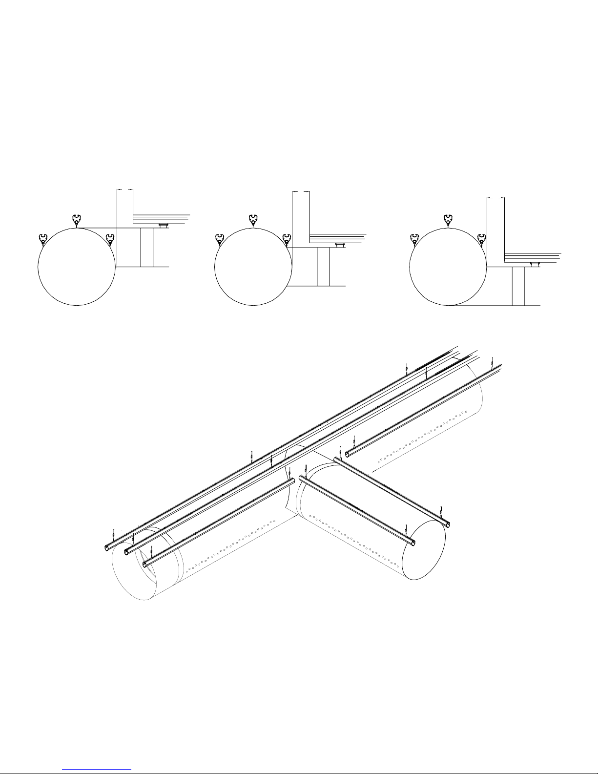
T’s
There should be roughly 12” (305mm) from sidewall of DuctSox to start of the branch track. Track too
close to the main run may cause premature failure due to abrasion from the track.
Support around fabric ttings may require additional track supports.
NOTE: Offset distance of branch U-Track from main truck is approximately half of the main trunk diameter
plus 12” (305mm).
12”
(305mm)
12”
(305mm)
12”
(305mm)
12
Installation Guide:
U-Track
Page 13
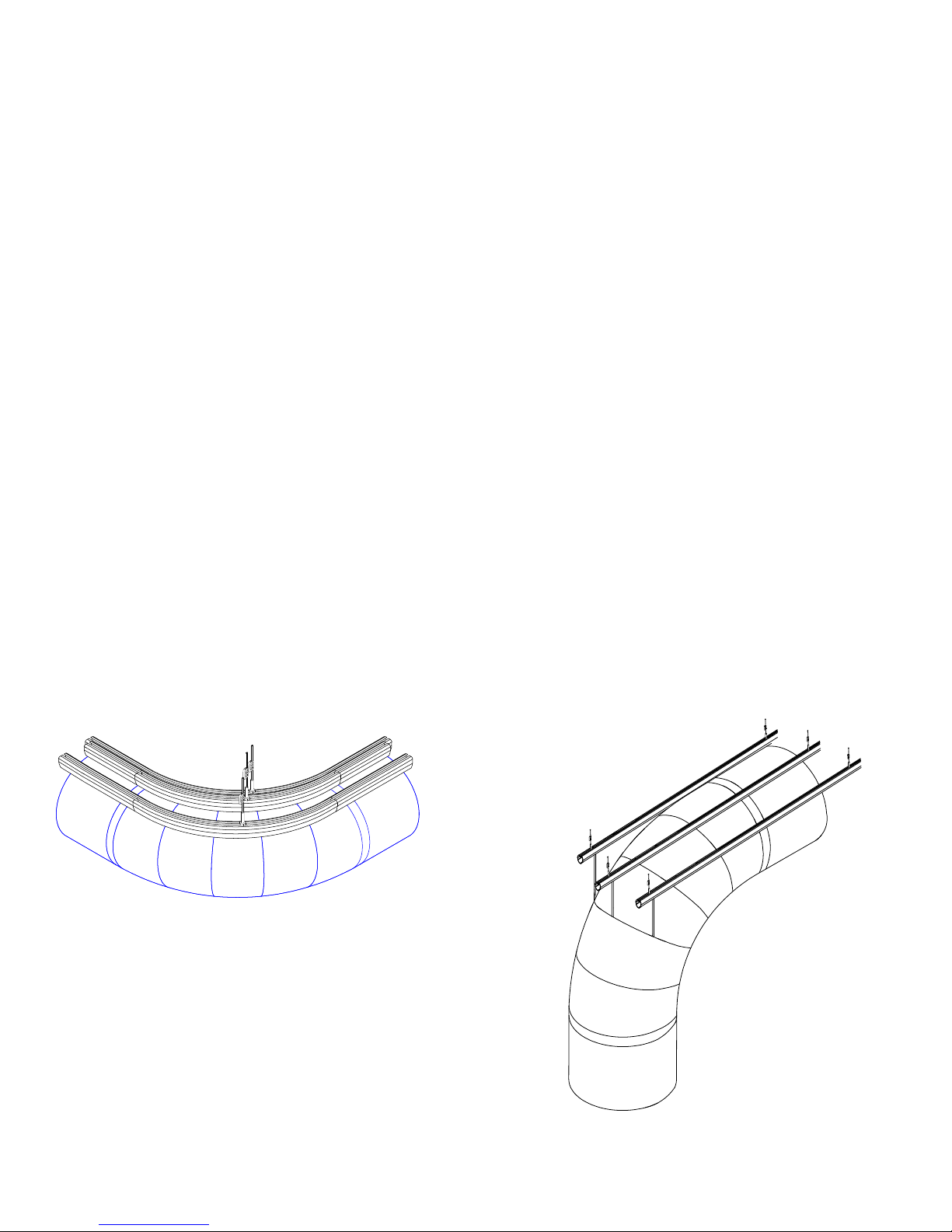
Elbows
Radius tracks are manufactured to match the radius of the DuctSox. This is typically 1.5 times the
diameter of the DuctSox.
For example, the inside radius track of a 74” diameter DuctSox would have a radius of 79.2”.
74” x 1.07 = 79.2”
((74” x 1.5) - (74”/2 x .866) = 79.2”)
The center 12:00 radius track would have a radius of 111”.
(74” x 1.5 = 111”)
And the outside radius track of a 74” diameter DuctSox would have a radius of 142.8”.
74” x 1.93 = 142.8”
((74” x 1.5) + (74”/2 x .866) = 142.8”)
Install at least one support per radius section, in the center if possible.
Coupler will not go into radius track the full 6” (150mm) and it shouldn’t. Coupler must only be inserted
into radius track 1.5” (38mm). This connection will only use one screw in the radius track portion. There
will be 3” (51mm) radius couplers when splicing radius-to-radius connections.
Radius track will only work with DuctSox that are installed in a true horizontal plane (Figure A).
Vertical elbows are supported by D-ring straps rather than radius track (Figure B).
Figure A Figure B
13
Installation Guide:
U-Track
Page 14
Step 4
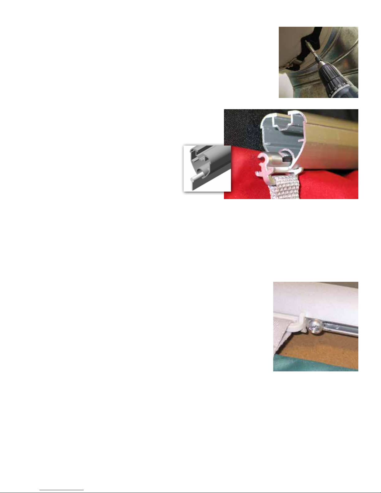
Install DuctSox Fabric. DuctSox Inlet must be attached to the metal collar using
screws (not included) through plastic patches on the Inlet Belt. Be sure to locate
the zipper start and seam at the 12:00 orientation for proper alignment.
Slide Glider or Cord-In attachments of the DuctSox into the
U-track bottom channel. Unzip ttings and slide them in
place independently of the straight sections. Close all zipper
connections before moving to Step 5.
Cord-In
Glider
Step 5
Start Up AHU. Turn on the AHU and inate the DuctSox System. Check all Gliders and sections to ensure
system is inating properly. If required, move Gliders to eliminate puckering at binding locations. If lengths
do not t properly, double check all eld measurements and compare to drawings. If all measurements are
correct, contact your DuctSox factory rep to discuss options.
Once system is properly adjusted, inate the system, pull the last Glider in each straight section (including
straight sections between ttings), and secure tension using Track Stop Screws. Also, be sure to install a
Track Stop Screw into the U-Track at the Endcap Glider, at the Inlet Glider, and at each Glider immediately
adjacent to all ttings.
The Track Stop Screw is used to keep sections of DuctSox from moving
lengthwise in the U-track. They also are used to put a slight tension on straight
sections of DuctSox (straight sections may consist of more than one zippered
section of DuctSox). The screw is tightened into the bottom channel to lock the
stop at locations where Gliders are to be locked in place. The Track Stop Screw
is not used with a Cord-In DuctSox system.
If the system includes elbows or T’s, secure Gliders before and after these
ttings. Failure to install DuctSox Systems correctly may void warranty.
Track Stop Screw
Step 6
Air Balancing. System must be balanced to design CFM and static pressure immediately after installation.
Most DuctSox Systems include a zipper at the inlet location for easy access to monitor ow.
If the fabric is uttering after balancing, please contact your factory rep immediately. Solutions to the
uttering include adjusting the Adjustable Flow Device (AFD), adding AFDs, or other solutions that would
result in a less turbulent airow.
14
Installation Guide:
U-Track
Page 15

Laundering Instructions
Sedona-Xm, TufTex, Verona, DuraTex, Microbe-X, Rx, and Stat-X fabrics:
• Remove the DuctSox fabric from your system, being sure to unzip all sections. Take care in recording
where each section was installed.
• Turn soiled side out, soak in cold water for 30 minutes.
• Wash cold, gentle cycle.
• Rinse thoroughly (repeat cycle if water/DuctSox still soiled).
• Drip dry or no-heat tumble dry.
15
Installation Guide:
U-Track
Page 16

If any questions arise regarding the installation of your
U-Track System, contact us.
?
866-382-8769 or 563-588-5300
Ph: 866-382-8769 or 563-588-5300
9866 Kapp Court
www.ductsox.com
Peosta, IA 52068
Fax: 563-588-5330
© 2 0 1 1 D u c t S o x C o r p .
DSUTRKIG0911B
 Loading...