


Duct-O-Wire®
CAS-2L100 DUPLEX
BI-DIRECTIONAL LASER COLLISION AVOIDANCE KIT
INSTALLATION AND OPERATING INSTRUCTIONS
This product incorporates IR Laser Protection Class 2; visible laser light.
Do Not Stare Into The Laser Beam!
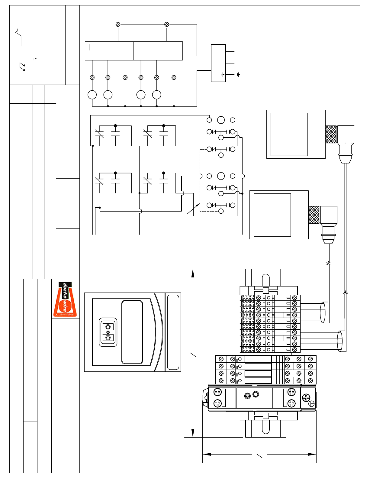
C1,C2 Relay coils are 120VAC rated.
The Q1,Q2,Q3,Q4 coils are controlled by a 24 VDC laser.
This unit may not be suitable for all applications.
Before installation you will need a qualified technician to verify this unit will work with your
application.
The Duct-O-Wire® CAS-2L100 DUPLEX Two Event Laser Collision Avoidance Kit comes with (2) Laser Sensor Units,
(2) Sensor Mounting Brackets and Hardware, (2) 10 Meter Data Cables, (1) DIN Mounted Power/Relay Module,
(2) Reflector Arrays with Mounting Hardware, Schematic Sheets and Warning Labels.
Laser Class2 Max Power 4.1 mW Time Base 100 s Pulse Duration 1.3 ms
Wave Length 650 mm Compliance: 21 CRF PART 1040 ENC60825-1:2003-10
MAKE CERTAIN THAT THE POWER SUPPLY IS DISCONNECTED BEFORE INSTALLING, REPAIRING, OR MAKING
ADJUSTMENTS TO THIS DEVICE. THIS DEVICE IS TO BE INSTALLED BY QUALIFIED ELECTRICAL PERSONNEL ONLY.
MOUNTING AND ALIGNMENT
1. Mount sensor and reflector using supplied bracket and hardware to suitable locations for stability and
proper alignment. Use 3 point alignment method to ensure the laser and reflector are in a straight line,
both horizontally and vertically true.
2. Connect the supplied data cable to the sensor and power/relay module per the drawing.
3. Attach the supplied Laser Warning Label in the immediate vicinity of the sensor unit.
4. Connect 110 VAC to the transformer per the schematic drawing.
5. A visible red light will be seen from the sensor to the reflector. Do Not Stare Into the Laser Light.
SENSOR PROGRAMMING-FEET MODE (
NOTE: ALL BUTTON PRESSES MST BE DONE WITHIN 15 SECONDS
1. Press and release the Mode/Enter button until EF is displayed. (multiple presses)
2. Press and release the SET button.
3. Press and release the Mode/Enter button until Uni is displayed. (6 button presses)
4. Press and hold the SET button until FEET is displayed, and release.
5. Press and release the Mode/Enter button once to confirm.
6. Wait 15-20 seconds and the unit will return to the “run” mode.
7. When sensor is in Run mode, distance to target is displayed in feet.
SENSOR PROGRAMMING-SET POINT 1
NOTE: If the desired distance is passed, the counter will need to be advanced until the set point is displayed
again. ALL BUTTON PRESSES MUST BE DONE WITHIN 15 SECONDS.
1. Press and release the Mode/Enter button until SP 1 is displayed. (2 presses)
2. Press and hold the SET button until the desired distance for the first event is displayed, then release.
3. NOTE: Minimum distance is 1 meter (3.28 feet).
4. Press and release the Mode/Enter button once to confirm. The display will show SP 1.
Use a pen or small blunt object for improved response
First Event Distance Q1 and Q3
(
)
)

5. Wait 15 to 20 seconds and the unit will return to the “run” mode.
SENSOR PROGRAMMING-ENABLE SET POINT 2
NOTE: ALL BUTTON PRESSES MUST BE DONE WITHIN 15 SECONDS
1. Press and release the Mode/Enter button until OU2 is displayed. (3 presses )
2. Press and hold SET button until Hno is displayed, then release.
3. Press and release the Mode/Enter button to confirm.
4. Wait 15 to 20 seconds and the unit will return to the “run” mode.
SENSOR PROGRAMMING-SET POINT 2 (
Second Event Distance Q2 and Q4
)
NOTE: ALL BUTTON PRESSES MUST BE DONE WITHIN 15 SECONDS
1. Press and release the Mode/Enter button until SP 2 is displayed. (4 presses)
2. Press and hold the SET button until the desired distance for the second event is displayed, then release.
3. NOTE: Minimum distance is 1 meter (3.28 feet).
4. Press and release the Mode/Enter button once to confirm. The display will show SP 2.
5. Wait 15 to 20 seconds and the unit will return to the “run” mode.
**REPEAT STEPS FOR 2ND SENSOR**
YOUR LASER COLLISON AVOIDANCE SYSTEMS SHOULD NOW BE READY TO OPERATE. PLEASE ENSURE THAT THE
LED’S ON THE CONTROL UNIT LIGHT WHEN CRANE IS MOVED TO EACH SET POSITION.
FACTORY RESET-ONLY IF REQUIRED
1. In the event that improper selections were made during the previous sensor programming steps, it may
be necessary to reset the unit to factory settings. Perform the following steps ONLY if required or the
sensor is not responding as intended.
2. Press and release the Mode/Enter button until EF is displayed. (multiple presses required)
3. Press and release the SET button once.
4. Press and release the Mode/Enter button until rES is displayed
5. Press and hold SET button until ---- (4 dashes) is displayed
6. Confirm by pressing the Mode/Enter button once.
7. After performing the factory reset you must repeat the SENSOR PROGRAMMING steps outlined in the
steps above.
*****The Duct-O-Wire CAS-2L100 Duplex includes two extra relays that make it possible to split the 2nd speed
from your pendant into two separate signals to the VFD drive. You may need to change your drive settings
from infinitely variable to stepping. Depending on your drive it may be possible using the extra contacts to use
the infinitely variable setting on your drive. However; this would be decided by a qualified technician. *****
The C1, C2 contacts are rated 120VAC. If you need a 24VDC rated coil please consult factory.
The Q1, Q2, Q3, Q4 relays are controlled by a 24VDC laser.
C1 is controlled from the Q2 Forward relay.
C2 is controlled from the Q4 Reverse relay.
Q1 is Forward 2nd speed.
Q3 is Reverse 2nd speed.
FINISH:
63
MAX.
.002"
REV DESCRIPTION DATE APPROVED
.XXXX -NT'D.
.X -.015
.XX -.010
.XXX -.005
STD. TOL:
including implied warranty of
TOLERANCES: PLUS OR MINUS
FRACTIONS: 1/32"
10
SENSOR 2
10
BRN
Q3
Q4
WHT
HOLES
20
BLK
BLU
40
Q2
WHT
2
30
BLK
Q1
4
BRN
1
BRN BLU
SENSOR 1
1
BLU
L N
POWER SUPPLY
3
V+ V-
24 VDC
120 VAC
X1 X2
fitness for a particular use.
drawings available on an "as
any kind with regard to the
drawing are disclaimed,
This drawing and information
contained herein is for general
DISCLAIMER:
information purposes only.
Note that DOW makes these
is" basis. All warranties of
'S
3
4
2
30
40
20
(A1) (A2)
NOTES:
OVERALL DIMENSIONS: L x W x H
OVERALL DIMENSIONS: 6-7/8" x 3-25/32" x 3-7/8"
C1 AND C2 ARE 120 VAC COIL
PLEASE REVIEW WIRING SCHEMATIC FOR THIS SYSTEM BEFORE
INSTALLATION TO ENSURE COMPATIBILITY FOR YO UR INTENDED
PURPOSE.
Q4
Q3
(A1) (A2)
(A1) (A2)
(A1) (A2)
Q1
Q2
REV. NO: SHEET JOB NO DRAWING NO:
CAS-2L100 DUPLEX1 of 1
C1
A1
FWD FROM
SET
MODE
(14)
(14)
PENDANT
PENDANT
TOP VIEW
(11)
REV FROM
(11)
2ND SPEED
SENSOR
Q2
(12)
Q4
MAT'L: PART NO:
FINISH: ASS'Y NO:
02/26/2018 APL
TITLE:
DATE: DRAWN BY: APPROVED BY: SCALE:
CAS-2L100 DUPLEX LASER COLLISION AVOIDANCE
DUCT-O-WIRE COMPANY
CORONA, CA 92878
P.O. BOX 519
800-543-3885
1351 WEST SECOND ST.
OCONOMOWOC, WI 53066
800-434-0062
(12)
FWD TO DRIVE
REV TO DRIVE
ENTER
TO DRIVE
PHOTO-EYE
Q1
(11)
(14)
(12)
Q3
(11)
(14)
(12)
possible
may be
infinitely
added for
variable
POWER m FEET OUT1 OUT2
jumper wire
12
22
A1
12
22
6
7
8
"
OUTPUT
A2
14
11
24
21
C2
A2
14
11
24
21
A2 A2
A1A1
A2 A2
A1A1
-V +V
24VDC 0.65A
X2 X2
2ND SPEE D FROM PENDANT
50
40
30
20
10
5
4
3
2
1
6-24 6-24
VV
6-24 6-24
VV
PS5R-VB24
ADJ
POWER SUPPLY
VR.
W
Q4
Q3
Q2
Q1
ON
15
0.35-0.19A
14 14
14 14
L N
100-240VAC
PHOTO-EYE
PHOTO-EYE
SENSOR
BLK
BLU
WHT
BRN
12 12
11 11
12 12
11 11
INPUT
50/60Hz
SENSOR
SENSOR CABLE
SENSOR CABLE
BLK
BLU
WHT
BRN
32
3
25
"
 Loading...