

Duct-O-Wire CAS-1RA-O Addendum
duct-a
®
Duct-O-Wire CAS-1RA-O Addendum
Collision Avoidance and Reflector Array Kit Instructions
EFFECTIVE NOVEMBER 2013
Your Duct-O-Wire CAS-1RA-O Collision Avoidance Kit comes co
bracket and hardware, (1) Plug, (1) Bushing, (2) Grommets, (1) Reflector Array and (1) Instruction sheet.
MAKE CERTAIN POWER SUPPLY IS DISCONNECTED BEFORE INSTALLING, REPAIRING, OR MAKING
ADJUSTMENTS TO THIS DEVICE. THIS DEVICE SHOULD BE INSTALLED BY QUALIFIED ELECTRICAL
PERSONNEL ONLY.
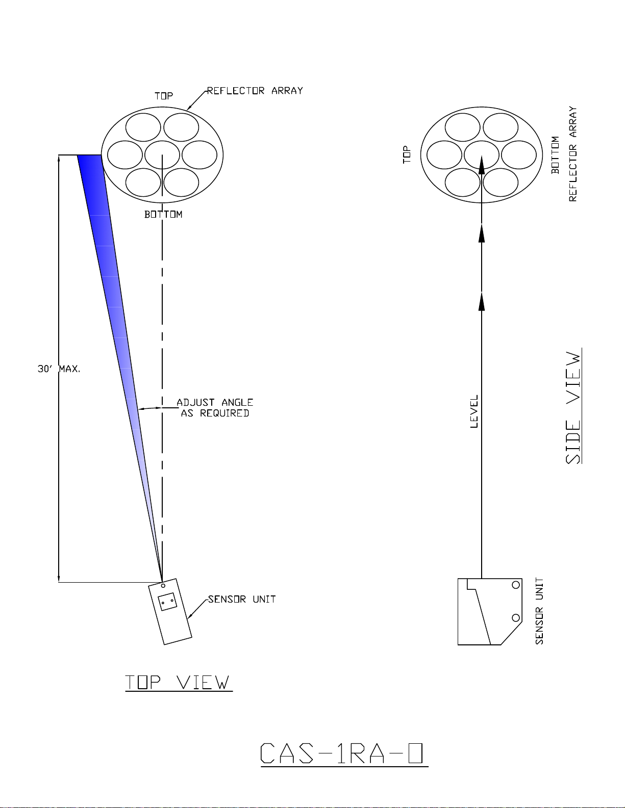
THIS PRODUCT IS DESIGNED FOR OPERATING DISTANCES OF 30 FEET MAXIMUM AND THREE
FEET MINIMUM. DO NOT EXCEED THESE DISTANCES.
SENSOR RATING: 3 AMPS MAX
mplete with (1) Sensor Unit, (1) Sensor Unit mounting
1. When mounting the sensor to the bracket, make sure the screw heads are on the bracket side and the
nuts are captive inside the sensor. Do not over tighten the sensor mounting screws.
2. Wire the sensor with a round cable, properly rated for voltage and application. The rubber bushing must
fit tightly around the cable. Always use the provided plug to seal the remaining entrance. As with all
sensors of this type, it is important to keep dust, moisture and contaminants from the inside of the unit.
The hole size for the cable entry into the sensor unit has been reduced from previous versions. It is
necessary to slide the compression nut and the rubber bushing onto the cable prior to stripping bac
the outer jacket for wiring. After wiring, fully tighten compression nut prior to reassembling.
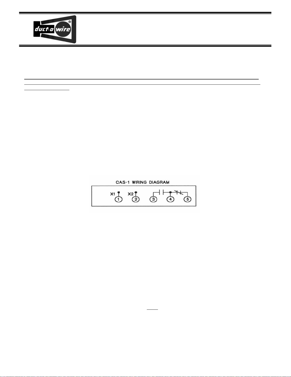
CAS-1 WIRING DIAGRA
xi T X2 t H I-r
© ® © ®
M
n
®
k
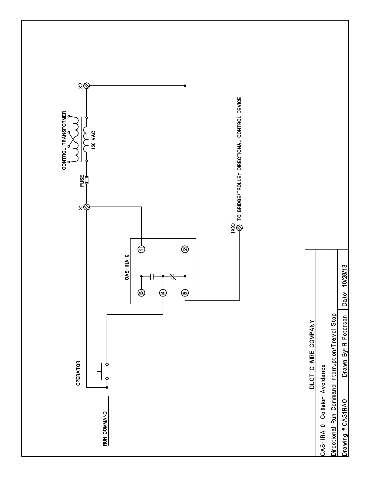
3. This sensor operates on 120 VAC. Connect power leads to terminals 1 and 2.
4. Terminals 4 and 5 are normally closed and are the ones generally used for Collision Avoidance
applications. They should be wired in series with the direction circuit to be interrupted.
5. Mount the reflector array securely to a solid object. The reflector array must be centered and
aligned both horizontally and vertically on the same plane as the sensor unit. (see diagram)
6. To adjust the trigger point: (A) With the crane positioned at the trigger point, move the sensor unit
so that the visible red light spot is just to the left or right of the reflector array. (B) Slowly move the
sensor unit towards the center of the reflector array until the indicator light on the sensor switches on.
The visible red light spot will be at the edge of the reflector array. (C) Secure the sensor unit in this
position. (D) Check the switching action by moving closer to and further away from the trigger zone.
(E) Slight adjustment of the sensor unit may be necessary to attain desired switching point.
7. Do not adjust the sensitivity on the sensor unit. It must remain in the factory set, full clockwise,
maximum gain position.
8. If multiple photoelectric units are being used in the same proximity, installation locations must be far
enough apart that there is no chance that one sensor will intercept the light beam from another unit.
9. As with all photoelectric sensors, it is necessary to keep excessive dust or dirt from diminishing the
optical effectiveness of the device. Wiping the sensor’s optical surface and the reflector array
occasionally with a moist, not wet, cloth should be made part of a normal maintenance procedure.
 Loading...