

4200
Operation And Maintenance Manual
BEFORE OPERATING THIS TOOL, ALL OPERATORS SHOULD STUDY
THIS MANUAL, TO UNDERSTAND AND FOLLOW THE SAFETY
WARNINGS AND INSTRUCTIONS. IF YOU HAVE ANY QUESTIONS,
CONTACT WITH OUR REPRESENTATIVES OR DISTRIBUTOR.
1-800-245-3188 www.ductmate.com ductmate@ductmate.com
WARNING:

Operations And
4200
Maintenance Manual
Contents
Tool Specications ....................................................................................................................3
Nail Specications.....................................................................................................................3
External Tool Parts ....................................................................................................................3
Safety Instructions ....................................................................................................................4
Lubrication and Maintenance ...................................................................................................5
Actuating Tool ............................................................................................................................5
Operating the Tool ................................................................................................................. 6-8
Troubleshooting Guide .............................................................................................................8
Part Lists .............................................................................................................................. 9-12
Warranty ...................................................................................................................................12
TOOL SPECIFICATIONS
Height 17½” (444.5 mm)
Width 9” (228.6 mm)
Length 13½” (342.9 mm)
Weight 10.5 lbs (4.76 kgs)
Recommended Operating Pressure 70-120 psi (4.9-8.3 bar)
Air Consumption
Loading Capacity up to 200 fasteners
Noise Characteristic Values in Accordance with ISO 3774, ISO 11201
A-weighted single-event sound pressure level at aperator’s position
A-weighted single-event sound power level
A-weighted single-event surface sound pressure level
LpA,1s = 91 dBA
LwA,1s = 102 dBA
LpA,1s = 89 dBA
Vibration Characteristics Values in Accordance with ISO 8862-1
Weighted root mean square acceleration = 2.7 m/s
FASTENER SPECIFICATIONS
Smooth Wire-collated Coil Nails
Shank Diameters
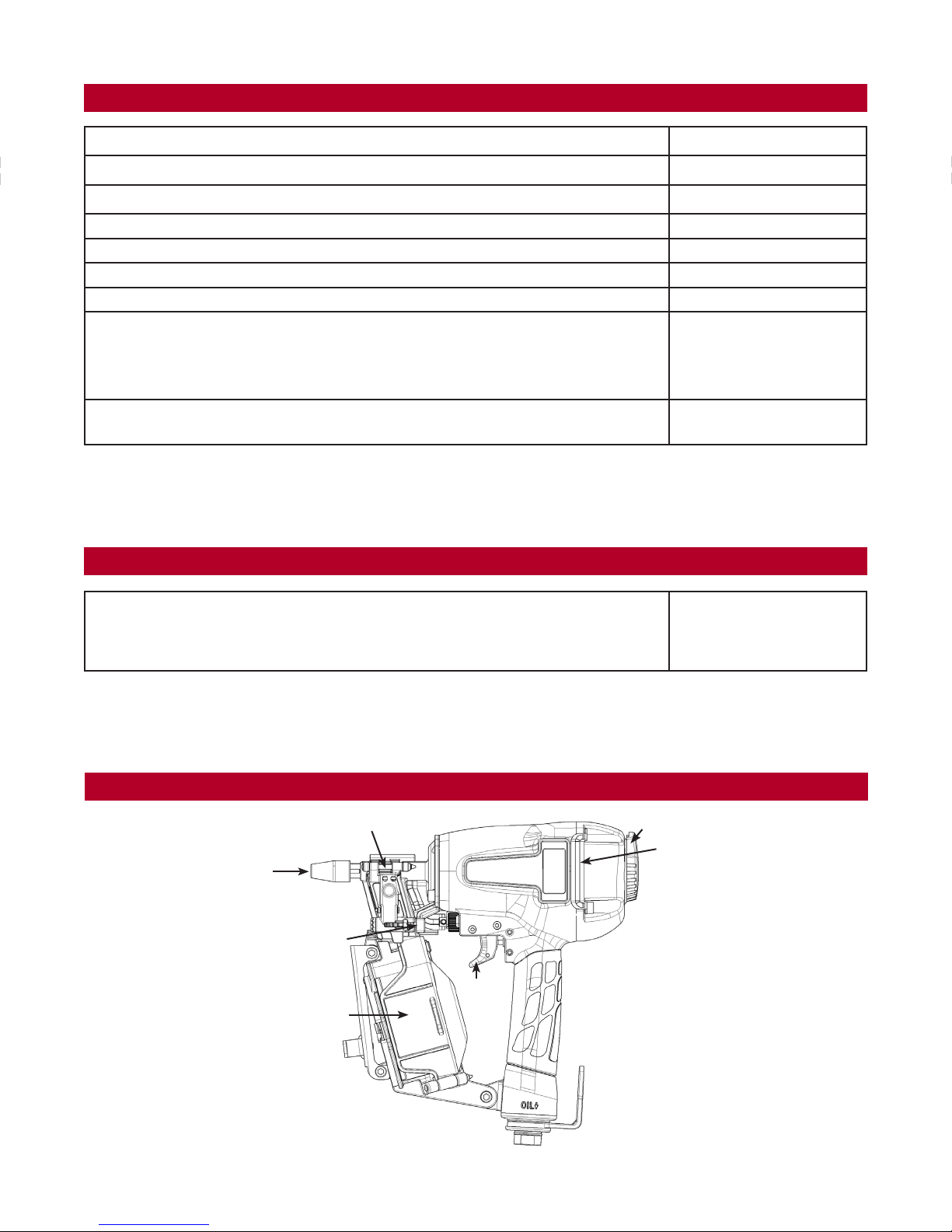
EXTERNAL TOOL PARTS
Nose
Safety Nose
Nail Lengths
Shank Type
Exhaust Deector
2
¾” - 1” (19.05-24.5 mm)
.001” (.025 mm)
Helical/Gripshank
Guide Cover
Door Latch
Magazine Assembly
Trigger
3.

SAFETY INSTRUCTIONS
WARNING: Read this manual and understand all instructions before operating the tool. If you have any questions, please contact with our
• Danger to the eyes always exists due to the possibility of dust, debris or fasteners flying up due to improper handling of the tool. For these
reasons safety glasses or goggles should always be worn when operating the tool.
The employer and/or user must ensure that proper eye protections and hearing protection is worn. Eye protection equipment must
conform to the requirements of the American National Standards Institute, ANSI Z87.1 (Council Directive 89/686/EEC of 21 DEC. 1989)
and provide both frontal and side protection.
• Ear protection may be required in some environments. As the working condition may include exposure to high noise levels which can
lead to hearing damage, the employer and user should ensure that any necessary hearing protection is provided and used by the
operator and others in the work area.
• Never use oxygen, carbon dioxide or any other bottled gas as a power source for this tool. Danger of explosion and/or serious personal
injury may result.
• Use only clean, dry regulated compressed air at recommended pressure
• Tools shall not be connected to pressure which potentially exceeds 175 psi or 12 bar.
• Air hose rated for a maximum operating pressure of 150 pst (10.3 bar) or 150% of the maximum system pressure, whichever is higher.
• Do not operate the tools near a flammable substance. Never operate tool near a flammable substance (thinner, gasoline, etc.). Volate
fumes from these substances could be drawn into the compressor and compressed together with the air resulting in an explosion.
• Disconnect tool from air supply and remove fasteners from magazine before doing tool maintenance, clearing a jammed fastener,
leaving work area, moving tool to another location, or handing the tool to another person.
• Use Correct Fittings. The connector on the tool must not hold pressure when air supply is disconnected. If the wrong fitting is used, the
tool can remain charged with air after disconnecting and thus will be able to drive a fastener even after the air line is disconnected,
possibly causing injury.
authorized representatives.
• Never use tool that is leaking air or has damaged or missing parts. Inspect screw tightness, loose or improperly installed screws or bolts
cause accidents and tool damage when the tool is put into operation. Inspect to confirm that all screws and bolts are tight and
properly installed prior to operating the tool. Never use the tool if any portion of the tool controls (trigger, contact arm) is inoperable,
disconnected, altered or not working properly.
• Never point the tools at co-workers or yourself at any time. Never actuate the tool into the air. This will avoid any hazard caused by
free flying fasteners and excessive strain of the tool. Always assume the tool contains fasteners.
Never carry the tool from place to place by the trigger or air hose.
• Do not alter or modify this tool from the original design or function without approval from us or authorized representatives. Do not
remove spring from contact trip, inadvertent actuation could occur.
• Always maintain proper footing and place yourself in a firmly balanced position when using or handling the tool. When using the tool in
an elevated place, secure the hose at a point close to the area you are going to drice fasteners. Accidents may be caused due to the
hose being pulled inadvertently or getting caught.
• Do not drive fasteners on top of other fasteners, the fasteners can ricochet and hurt someone.
• Never use the body of the tool or top cap as a hammer, always use the tool for its intended use. Do not discharge fasteners into
concrete, stone, or any material too hard for the fastener to penetrate.
• Do not drive fasteners close to the edge of the work surface. The workpiece may split causing the fastener to ricochet, fly free or hit someone.
• Keep hands and body away from the discharge area of the tool.
• Keep face and body away from back of the tool cap when working in restricted areas. Sudden recoil can result in hard impact to the body.
• Never use tool in the presence of flammable dust, gases, or fumes. The tool may produce a spark that could ignite gases causing a fire
and cause the tool to explode.
• Be aware of material thickness when using the nailer.
4.

LUBRICATION AND MAINTENANCE
• Use Pneumatic tool oil or a non-detergent oil. Do not use detergent oil or additives as they will damage o-rings
and rubber parts.
• Use a filter and regulator when possible.
• Add pneumatic oil into the air inlet twice daily (depending on frequency of tool use).
• Wipe tool clean daily and inspect for wear. Use solvents only if necessary - Do Not Soak (solvents may damage
o-rings and other tool parts).
• Drain compressor tanks and hosed daily.
• Clean magazine, pusher, and contact trip mechanism periodically.
• All screws, nuts and fasteners should be kept tight and undamaged. Loose screws results in unsafe operation
and parts breakage.
ACTUATION TOOL
WARNING: Always wear eye and hearing protection when operating tool.
Sequential Fire Trigger (Gray Color)
• To be used in applications where precise fastener placement is preferred.
• This trigger reduces the chances of double firing and unintentional firing.
1. With your finger off the trigger, press the safety nose all the way down on the surface of the material the
fastener is being driven into.
2. Pull the trigger firing a fastener into the material.
3. The tool will not fire again until the trigger is released and the safety nose removed completely from the
material being used.
4. To fire the next fastener repeat the above steps.
5.

OPERATING THE TOOL
Read Safety Instruction section of this manual.
Loading the tool:
WARNING: Always connect air before loading the tool.
Always wear safety goggles when operating the tool.
1. Open the magazine.
Pull down door latch and swing the door, then swing
magazine cover open.
2. Check adjustment.
The pin support can be adjusted up and down for
three settings. Set the position of the pin support
according to the pin length. The pins will not feed
smoothly unless the magazine is not adjusted
correctly. To change setting pull up on the post and
twist to the correct step.
3. Load the coil fasteners.
Place a coil of fasteners over the post in the
magazine. Uncoil enough of the pins to reach the
feed pawl, place the first pin in front of the feed pawl
into the driver channel and place the second pin
between the teeth of the feed pawl. The heads of the
pins must be in the slot in the nose.
4. Close the magazine.
Close the magazine cover and swing the door closed.
Be sure that the door is fully latched when released.
The tool is now ready to operate.
TEST OPERATION
1. Adjust the air pressure at 80 p.s.i. (5.5 bar) and
connect the air supply.
2. Without touching the trigger, depress the safety nose
against the work-piece. Pull the trigger. (The tool must
fire the fastener.)
3. With the tool off the work-piece, pull the trigger. Then
depress the safety nose against the work-piece. (The
tool should NOT fire the fastener.)
4. Adjust the air pressure as much as the lowest possible
according tot he diameters and length of fastener and
the hardness of work-piece.
6.

OPERATING THE TOOL Cont.
Adjusting Depth:
The depth that the fastener is driven can be adjusted using the depth adjustment next to the trigger of the tool.
WARNING: To reduce risk of serious injury from accidental actuation when attempting to adjust depth, ALWAYS;
1. To drive the nail shallower, turn the wheel (A) to the
right to the extent desired.
2. To sink a nail deeper, turn the wheel (A) to left to the
extent desired.
3. Make sure that the trigger and safety move freely up and
down without binding or sticking after each adjustment.
Clearing a Jammed Fastener
Should a pin jam occur, disconnect air supply from tool, keep the tool pointed away from you and follow these
instructions to clear. If the tool jambs, do not continue to fire the tool. This cause the driver blade to break.
1. Press down the door latch and swing the door.
2. Insert the rod into the nose to push the pin back up
and into the guide body bore.
3. Remove the jammed pin from driver channel.
4. Extract the pin with pliers or, if the pin is loose, turn
the tool upside-down and shake it out.
7.

OPERATING THE TOOL Cont.
Operation in Cold Weather
When operating tools at temperatures near and below freezing, the moisture in the air line may freeze and prevent
tool operation:
1. Reduce the air pressure to 80 psi (5.5 bar) or less.
2. Removed all fasteners from magazine.
3. Connect air and free-fire (blank-fire) the tool. Slow speed operation tends to worm up the moving part.
CAUTION: Do not store tool in a cold weather environment to prevent frost or ice formation on the tools
operating valves and mechanisms that could cause tool failure.
Operation in Hot Weather
Keep tool out of direct sunlight as excessive heat can deteriorate bumpers, o-rings and other rubber parts resulting in
increased maintenance.
TROUBLESHOOTING GUIDE
WARNING: Disconnect air from tool before all repairs!
Stop using the tool immediately if any of the following problems occur. Serious personal injury could occur. Any repairs
or replacements must be done by a qualified person or an authorized service center only.
PROBLEM CAUSE CORRECTIVE ACTION
Trigger valve leaks air
Frame and nose leaks air
Frame and cap leaks air
Skipping fasteners
Intermittent feed
Lack of power
Sluggish
Fasteners jam in tool Driver channel worn Replace nose/check door
O-rings in trigger valve housing are damaged Replace o-ring
Loose now screw Tighten screws and recheck
Damaged o-rings or gasket Replace o-ring or gasket
Bumper cracked/worn Replace bumper
Loose cap screws Tighten screws and recheck
Damaged seal or gasket Replace seal or gasket
Worn bumper Replace bumper
Dirt in nose Clean
Dirty/dry magazine Clean/lubricate use pneumatic tool oil
Damaged magazine Replace magazine
Air restriction/inadequate air ow Fitting hose or air compressor needs to be checked
Worn o-ring on piston or lack or lubrication Replace o-ring. Lubricate.
Trigger valve o-ring cut/worn Replace o-ring
Leaking cap gasket Tighten screw, replace gasket
Worn/damaged pusher spring Replace spring
Broken and damaged driver blade Replace driver blade
Fasteners too short or wrong size for tool Use recommended fasteners only
Bent fasteners Discontinue using these fasteners
Air leaks Tighten screws and ttings
Low air pressure Check air supply
Lack of lubrication Use pneumatic tool lubricant
Damaged or worn o-ring/sea Replace o-ring/seal
Exhaust blocked Check bumper, head valve spring
Wrong size fasteners Use recommended fasteners only
Bent fasteners Discontinue using these fasteners
Broken and damaged driver blade Replace driver blade
Loose magazine, nose screw Tighten all screws
8.

PART LIST REPEATER 4200
9.

PART LIST REPEATER 4200 Cont.
Item # Part # Description Qty
1 DST4200-1 Hex.Soc.Hd.Bolt 1
2 DST4200-2 Bushing 1
3 DST4200-3 Hex.Soc.Hd.Bolt - Lower 2
4 DST4200-4 Deector, Exhaust 1
5 DST4200-5 Guide Cover 2
6 DST4200-6 Cap 1
7 DST4200-7 Gasket, Cap 1
8 DST4200-8 Piston Stopper 1
9 DST4200-9 Spring 1
10 DST4200-10 O-Ring 1
11 DST4200-11 O-Ring 1
12 DST4200-12 Piston, Head Valve 1
13 DST4200-13 Seal 1
14 DST4200-14 O-Ring 1
15 DST4200-15 Cylinder Seal 1
16 DST4200-16 Cylinder Spacer 1
17 DST4200-17 O-Ring 1
18 DST4200-18 O-Ring 1
19A DST4200-19A Driver Assembly 1 Set
20 DST4200-20 O-Ring 1
21 DST4200-21 Cylinder 1
22 DST4200-22 Bumper 1
23A DST4200-23A Body Assembly 1 Set
24 DST4200-24 O-Ring 1
25 DST4200-25 End Cap 1
26 DST4200-26 O-Ring 1
27 DST4200-27 O-Ring 1
28 DST4200-28 Valve 1
29 DST4200-29 O-Ring 2
30 DST4200-30 O-Ring 1
31 DST4200-31 O-Ring 1
32 DST4200-32 Valve Plunger 1
33 DST4200-33 Spring 1
34 DST4200-34 O-Ring 2
35 DST4200-35 Plunger 1
36 DST4200-36 Plunger Cap 1
37A DST4200-37A Trigger Assembly-Bump 1 Set
38 DST4200-38 Spring Pin 2
39 DST4200-39 Grommet 2
40 DST4200-40 Pin Trigger 2
41 DST4200-41 Guide, Contact Trip 1
42 DST4200-42 Spring, Safety 1
43 DST4200-43 Upper Safety Lever 1
44 DST4200-44 E-Ring 1
45 DST4200-45 Adjusting Nut 1
46 DST4200-46 O-Ring 1
47 DST4200-47 Ball, Steel 2
Item # Part # Description Qty
48 DST4200-48 Adjusting Spring 1
49 DST4200-49 Adjusting Post 1
50 DST4200-50 Gasket 1
51 DST4200-51 Nose 1
52A DST4200-52A Magnet Bushing Assembly 1 Set
53 DST4200-53 Hex.Soc.Hd.Bolt - Lower 2
54 DST4200-54 Spring 1
55 DST4200-55 Feed Pawl 1
56 DST4200-56 O-Ring 6
57 DST4200-57 Roll Pin 2
58 DST4200-58 Feed Piston 1
59 DST4200-59 O-Ring 1
60 DST4200-60 Feed Spring 1
61 DST4200-61 Feed Piston Bumper 1
62 DST4200-62 Feed Piston Cover 1
63 DST4200-63 C-Ring 1
64 DST4200-64 Shaft Pin Nail Guide 2
65 DST4200-65 Spring 1
66 DST4200-66 Nail Stopper 1
67 DST4200-67 Nail Guide 1
68 DST4200-68 Spring Pin 1
69 DST4200-69 Spring, Lock Shaft 1
70 DST4200-70 Lock Shaft 1
71 DST4200-71 Magazine Cover 1
72 DST4200-72 Tension Post Bushing(Upper) 1
73 DST4200-73 Spring 1
74 DST4200-74 Nail Holder 1
75 DST4200-75 Adjust Post 1
76 DST4200-76 Magazine 1
77 DST4200-77 Magazine Guide 1
78 DST4200-78 Screw 3
79 DST4200-79 Tension Post Bushing 1
80 DST4200-80 Safety Cover 1
81 DST4200-81 Bushing 1
82 DST4200-82 Hex.Soc.Hd.Bolt 2
83 DST4200-83 Lower Safety Lever Assembly 1
84 DST4200-84 Safety Nose 1
85 DST4200-85 Hex.Soc.Hd.Bolt 1
86 DST4200-86 Flat Washer 1
87 DST4200-87 Locknut 1
88 DST4200-88 Logo Decals 1 Set
89A DST4200-89A Belt Hook Assembly 1
89A-1 DST4200-89A-1 End Cap 1
89A-2 DST4200-89A-2 Belt Hook Assembly 1
89A-3 DST4200-89A-3 O-Ring 1
89A-4 DST4200-89A-4 Cover Belt Hook 1
89A-5 DST4200-89A-5 C-Ring 1
10.

PART LIST REPEATER 4200 FRAME
11.

PART LIST REPEATER 4200 FRAME Cont.
Item # Part # Description Quantity
1 R1002-06 CYL ROD CLEVIS KIT 1
2 R1002-05 AIR CYLINDER 1
3 RW1043-04 5/32" PUSH CONN. 1/8" NPT THD 1
4 SCREW SHL 3/8-3 3/8" x 2" SHOLDER SCREW 1
5 REPEATER 4200 S REPEATER 4200 SPACER 2
6 SHCS M6X30 BOLT M6 x 30 4
7 REPEATER 4200 B FLANGE BEARING 3/8" x 5/8" x 1/2" 2
8 RP1013 TOGGLE CLAMP WELDED 1
9 LOCKNUT NY 5/16 5/16" NYLON LOCKNUT 2
10 CORNERPR1006 10-24 MACHINE SCREW NUT 2
11 SBH 10-24X3/4 10-24 BUTTON HEAD CAP SCREW 2
12 REPEATER 4200 H HANDLE WELDED 1
13 R1002-13 HANDLE GRIP 1
14 R1002-01 10/32" TAC VALVE 1
15 R1002-02 10/32" UNIV. ELBOW 1
16 REPEATER 4200 F REPEATER 4200 FRAME ASSEMBLY 1
17 SCREW SHL 3/8-2 3/8" x 1-1/4" SHOLDER SCREW 1
18 RW1045 5/32" PUSH CONN. 10-32 THD 2
19 RW1043-02 5/32" PUSH CONN. 1/4" NPT THD 1
20 RW1044 1/4" NPT STREET RUN TEE 1
N/A RW1048 5/32"OD POLYFLO TUBING 2.5 ft
N/A R1002-09-1 1/4" OD POLYFLO TUBING 2.5 ft
LIMITED PRODUCT WARRANTY
Ductmate warrants that the Repeater 4200, when properly installed and maintained, will be free from defects in material and workmanship,
and will comply with all written specications made by Ductmate at the time of sale. Ductmate’s warranty shall run for a period of one year
from the date of manufacture.
Warranty Limitation
The warranty stated above is in lieu of all other warranties, express or implied, including but not limited to the implied warranties of
MERCHANTABILITY AND FITNESS FOR A PARTICULAR PURPOSE. Although Ductmate may have suggested the product, or provided
written or oral advice to the Purchaser, it is the Purchaser’s responsibility to test and determine the suitability of the Repeater 4200, for the
intended use and purpose, and Purchaser and/or its customer assumes all risk and liability whatsoever regarding such suitability.
Limitation of Liability
In the event of a breach of the above warranty, Ductmate’s sole obligation, and Purchaser’s sole and exclusive remedy, shall be, at Ductmate’s
option, repair or replacement of any defective products, or refund of an applicable portion of the purchase price. Ductmate shall have no
liability for costs of removal or reinstallation of the product. The Purchaser agrees that no other remedy, including but not limited to loss of
prots, loss sales, injury to person or property, or any other special, incidental or consequential damages, shall be available to the Purchaser
for any claim arising out of this Agreement, regardless of whether such claim is made in contract or in tort, including strict liability in tort. In no
event will Ductmate be obligated to pay damages to the Purchaser in any amount exceeding the purchase price that the Purchaser paid to
Ductmate for the allegedly defective product.
Charleroi, PA
210 Fifth Street
Charleroi, PA 15022
800-245-3188
724-258-0500
FAX: 724-258-5494
www.ductmate.com
Lodi, CA
810 S. Cluff Avenue
Lodi, CA 95240-9141
800-245-3188
724-258-0500
FAX: 209-333-4678
704 - 11/13
12.
 Loading...