

DuctlessAire DA1221-H2-I, DA2421-H2-I, DA1821-H2-I, DA1221-H2-O, DA1821-H2-O Service Manual
...
D
UCTLESSAIRE MINI SPLIT
2017 SERVICE MANUAL


Table of Contents
Page
1. Safety Precautions ........................................................................................ 1
1. In case of Accidents or Emergency
2. Pre-Installation and Installation
3. Operation and Maintenance
2. Specifications ................................................................................................ 3
1. Model Reference
2. Electrical Wiring Diagrams
3. Product Features ........................................................................................... 8
1. Operation Modes and Functions
4. Maintenance and Disassembly .................................................................... 16
1. Maintenance
2. Disassembly
5. Troubleshooting ............................................................................................ 62
1. Safety Caution
2. General Troubleshooting
3. Error Diagnosis and Troubleshooting Without Error Code
4. Quick Maintenance by Error Code
5. Troubleshooting by Error Code
Appendix ............................................................................................................. 88
i) Temperature Sensor Resistance Value Table for T1,T2,T3 and T4 (°C – K)
ii) Temperature Sensor Resistance Value Table for TP (°C – K)
iii) Pressure On Service Port


Contents
1. In Case of Accidents or Emergency ......................................................................2
2. Pre-Installation .......................................................................................................2
3. Operation and Maintenance .................................................................................2
Safety Precautions

Safety
Precautions
Page 2
To prevent personal injury, or property or unit damage,
adhere to all precautionary measures and instructions
outlined in this manual. Before servicing a unit, refer to this
service manual and its relevant sections.
Failure to adhere to all precautionary measures listed in this
section may result in personal injury, damage to the unit or
to property, or in extreme cases, death.
WARNING indicates a potentially hazardous
situation which if not avoided could result in serious
personal injury, or death.
CAUTION indicates a potentially hazardous situation
which if not avoided could result in minor or
moderate personal injury, or unit damage.
1. In case of Accidents or Emergency
WARNING
•• If a gas leak is suspected, immediately turn off the
gas and ventilate the area if a gas leak is suspected
before turning the unit on.
•• If strange sounds or smoke is detected from the unit,
turn the breaker off and disconnect the power supply
cable.
•• If the unit comes into contact with liquid, contact an
authorized service center.
•• If liquid from the batteries makes contact with skin or
clothing, immediately rinse or wash the area well with
clean water.
•• Do not insert hands or other objects into the air inlet
or outlet while the unit is plugged in.
•• Do not operate the unit with wet hands.
•• Do not use a remote controller that has previously
been exposed to battery damage or battery leakage.
CAUTION
•• Clean and ventilate the unit at regular intervals when
operating it near a stove or near similar devices.
•• Do not use the unit during severe weather conditions.
If possible, remove the product from the window
before such occurrences.
2. Pre-Installation and Installation
WARNING
•• Use this unit only on a dedicated circuit.
•• Damage to the installation area could cause the unit
to fall, potentially resulting in personal injury, property damage, or product failure.
•• Only qualified personnel should disassemble, install,
remove, or repair the unit.
•• Only a qualified electrician should perform electri-
cal work. For more information, contact your dealer,
seller, or an authorized Midea service center.
CAUTION
•• While unpacking be careful of sharp edges around
the unit as well as the edges of the fins on the condenser and evaporator.
3. Operation and Maintenance
WARNING
•• Do not use defective or under-rated circuit breakers.
•• Ensure the unit is properly grounded and that a
dedicated circuit and breaker are installed.
•• Do not modify or extend the power cable. Ensure
the power cable is secure and not damaged during
operation.
•• Do not unplug the power supply plug during
operation.
•• Do not store or use flammable materials near the
unit.
•• Do not open the inlet grill of the unit during
operation.
•• Do not touch the electrostatic filter if the unit is
equipped with one.
•• Do not block the inlet or outlet of air flow to the unit.
•• Do not use harsh detergents, solvents, or similar items
to clean the unit. Use a soft cloth for cleaning.
•• Do not touch the metal parts of the unit when
removing the air filter as they are very sharp.
•• Do not step on or place anything on the unit or
outdoor units.
•• Do not drink water drained from the unit
•• Avoid direct skin contact with water drained from the
unit.
•• Use a firm stool or step ladder according to
manufacturer procedures when cleaning or
maintaining the unit.
CAUTION
•• Do not install or operate the unit for an extended
period of time in areas of high humidity or in an
environment directly exposing it to sea wind or salt
spray.
•• Do not install the unit on a defective or damaged
installation stand, or in an unsecure location.
•• Ensure the unit is installed at a level position
•• Do not install the unit where noise or air discharge
created by the outdoor unit will negatively impact the
environment or nearby residences.
•• Do not expose skin directly to the air discharged by
the unit for prolonged periods of time.
•• Ensure the unit operates in areas water or other
liquids.
•• Ensure the drain hose is installed correctly to ensure
proper water drainage.
•• When lifting or transporting the unit, it is
recommended that two or more people are used for
this task.
•• When the unit is not to be used for an extended time,
disconnect the power supply or turn off the breaker.

Contents
1. Model Reference ....................................................................................................4
2. Electrical Wiring Diagrams ....................................................................................5
2.1 Indoor Unit ....................................................................................................5
2.2 Outdoor Unit .................................................................................................6
Specifications
Specifications
Page 4
1. Model Reference
Refer to the following table to determine the specific indoor and outdoor unit model number of your purchased
equipment.
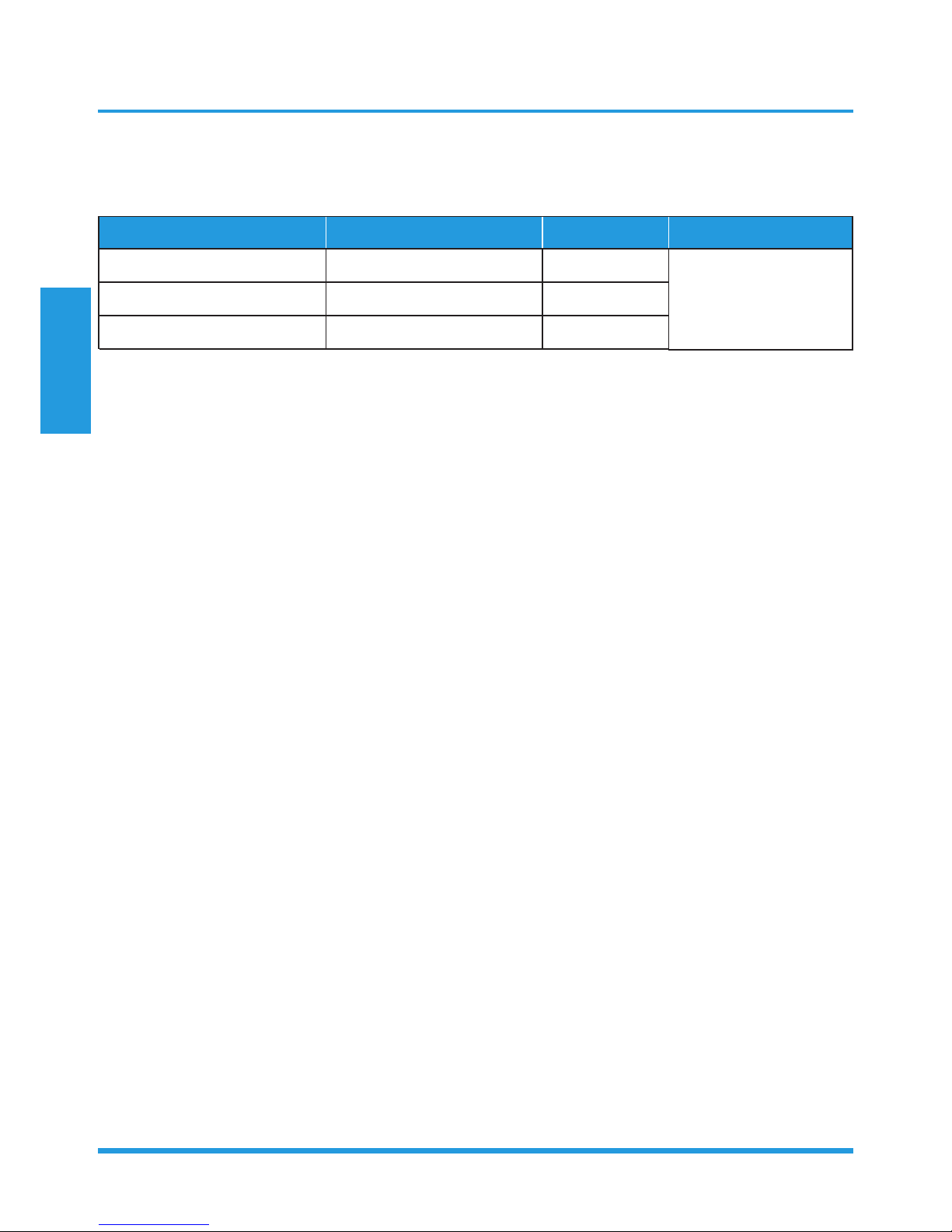
Indoor Unit Model Outdoor Unit Model Capacity (Btu) Power Supply
208/230V~, 60Hz, 1Phase
DA1221-H2-I DA1221-H2-O
12K
DA1821-H2-I
DA1821-H2-O
18K
DA2421-H2-I DA2421-H2-O
24K
Specifications
Page 5
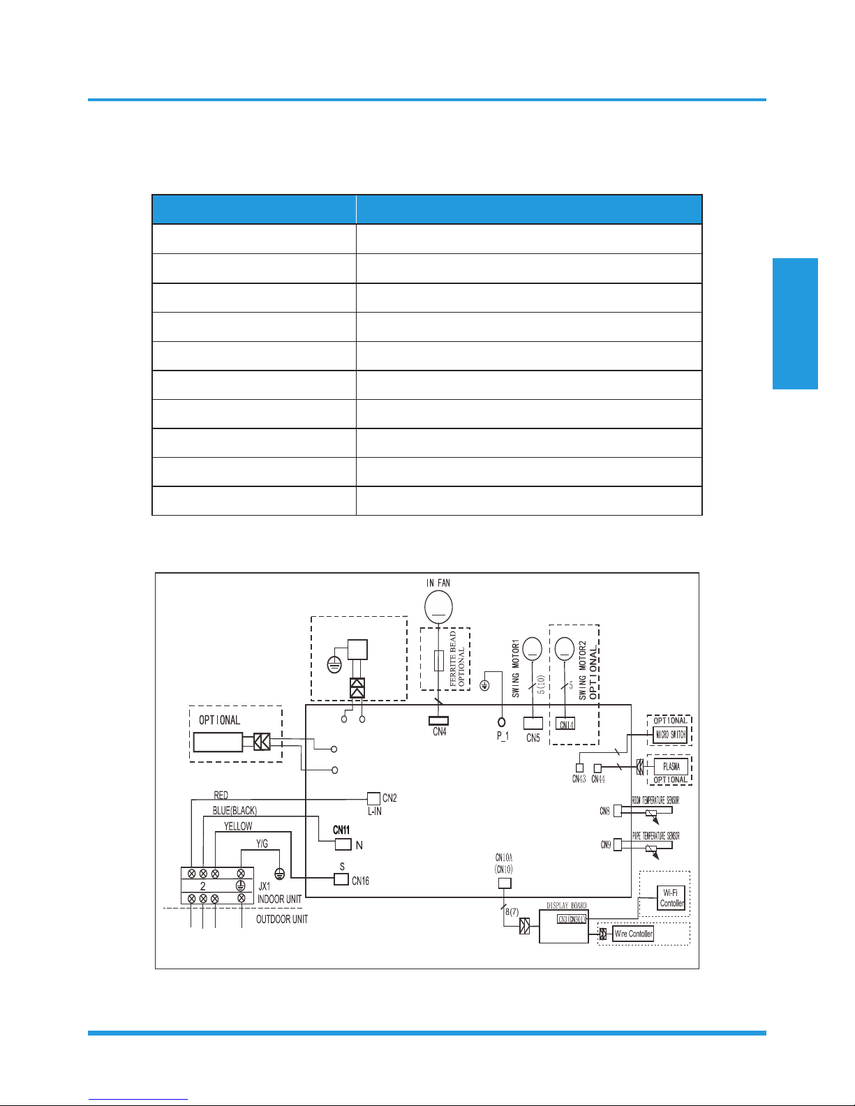
2. Electrical Wiring Diagrams
2.1 Indoor unit
Abbreviation Paraphrase
Y/G Yellow-Green Conductor
ION Positive and Negative Ion Generator
CAP Capacitor
PLASMA Electronic Dust Collector
L LIVE
N NEUTRAL
Heater The Electric Heating Belt of Indoor Unit
T1 Indoor Room Temperature
T2 Coil Temperature of Indoor Heat Exchanger Middle
EEV Electirc Expansive Valve
DA1221-H2-I, DA1821-H2-I, DA2421-H2-I:
INDOOR WIRING DIAGRAM
M
CN6_1
CN12_1
CN6_2
CN12_2
M
M
5
2
2
16022000019694
I ON
OPT I ONAL
Y/ G
HEATER
1
3
OPTIONAL
OPTIONAL
Specifications
Page 6
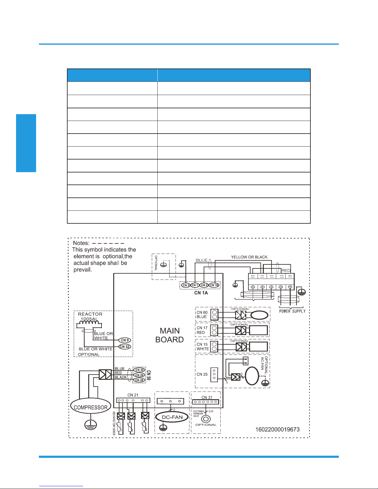
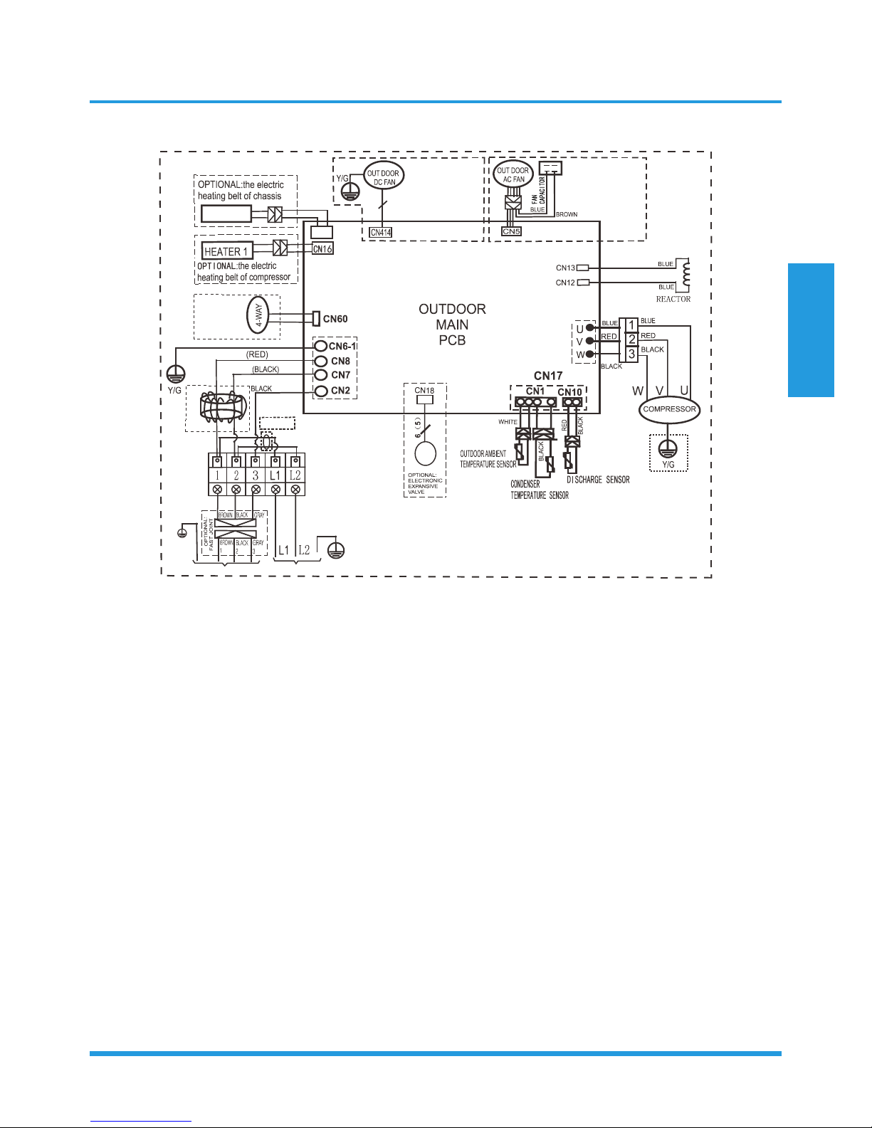
2.2 Outdoor Unit
Abbreviation Paraphrase
4-WAY Gas Valve Assembly/4-WAY VALVE
AC-FAN Alternating Current FAN
DC-FAN Direct Current FAN
CT1 AC Current Detector
COMP Compressor
L-PRO Low Pressure Switch
H-PRO High Pressure Switch
T3 Coil Temperature of Condenser
T4 Outdoor Ambient Temperature
TH Compressor Suction Temperature
TP Compressor Discharge Temperature
DA1221-H2-O:
4-WAY
OPTIONAL:
DC-FAN
CN 7
PAN
HEATER
CRANKCASE
HEAT ER
BROWN
I NDOOR UNI T
3
2
L1
L2
BLUE OR BLACK
1
Y/G
AMBIENT TEMP. SENSOR
CONDE NSER TEMP SENSOR.
Y/G
Y/G
Y/G
U
V
W
BLUE
RED
BLACK
AC-FAN
CAPACITOR
Y/G
Y/G
Y/G
Specifications
Page 7
DA1821-H2-O, DA2421-H2-O
R
E
D
BL
ACK
(
BL
UE)
OPTIONAL:
16022000019211
HEATER 2
CN4
OUTDOOR WIRING DIAGRAM
3
Applicable to
the units adopting
DC motor only
Applicable to
the units adopting
AC motor only
CN30
B
R
O
W
N
BLUE
()YELLOW
CN3
O
PT
IO
N
AL
OPTIONAL
POWER SUPPL Y
TO I NDOOR UNI T
Y/G

Contents
1. Operation Modes and Functions ..........................................................................9
1.1 Abbreviation ..................................................................................................9
1.2 Safety Features ..............................................................................................9
1.3 Display Function ..........................................................................................10
1.4 Fan Mode ....................................................................................................10
1.5 Cooling Mode .............................................................................................10
1.6 Heating Mode .............................................................................................10
1.7 Auto-mode ..................................................................................................11
1.8 Drying Mode ...............................................................................................11
1.9 Forced Operation Function ..........................................................................11
1.10 Timer function .............................................................................................11
1.11 Economy function .......................................................................................12
1.12 Auto-Restart Function ..................................................................................12
1.13 Refrigerant Leakage Detection .....................................................................12
1.14 Louver Position Memory Function ................................................................12
1.15 8°C Heating(Optional) ................................................................................12
1.16 Self Clean(Optional) ....................................................................................12
1.17 Follow Me(Optional) ...................................................................................12
1.18 Silence(Optional) .......................................................................................12
1.19 Information Inquiry ......................................................................................13
Product Features

Product Features
Page 9
1. Operation Modes and Functions
1.1 Abbreviation
Unit element abbreviations
Abbreviation Element
T1 Indoor room temperature
T2 Coil temperature of evaporator
T3 Coil temperature of condenser
T4 Outdoor ambient temperature
TS Set temperature
TP Compressor discharge temperature
1.2 Safety Features
Compressor three-minute delay at restart
Compressor functions are delayed for up to one minute
upon the first startup of the unit, and are delayed for up
to three minutes upon subsequent unit restarts.
Temperature protection of compressor top
The unit will stop working when the compressor top temp.
protector cut off, and will restart after the compressor top
temp. protector restart.
Automatic shutoff based on discharge temperature
If the compressor discharge temperature exceeds 115°C
for five seconds, the compressor ceases operation.
Automatic shutoff based on fan speed
If the indoor fan speed registers below 300RPM for an
extended period of time, the unit ceases operation and the
corresponding error code is displayed on the indoor unit.
Inverter module protection
The inverter module has an automatic shutoff mechanism
based on the unit’s current, voltage, and temperature.
If automatic shutoff is initiated, the corresponding error
code is displayed on the indoor unit and the unit ceases
operation.
Indoor fan delayed operation
• When the unit starts, the louver is automatically
activated and the indoor fan will operate after a period
of 7 seconds.
• If the unit is in heating mode, the indoor fan is
regulated by the anti-cold wind function.
Compressor preheating
Preheating is automatically activated when T4 sensor is
lower than 3°C.
Sensor redundancy and automatic shutoff
• If one temperature sensor malfunctions, the air
conditioner continues operation and displays the
corresponding error code, allowing for emergency use.
• When more than one temperature sensor is
malfunctioning, the air conditioner ceases operation.
Refrigerant leakage detection
This function is active only when cooling mode is selected.
It will detect if the compressor is being damaged by
refrigerant leakage or by compressor overload. This is
measured using the coil temperature of evaporator T2
when the compressor is in operation.
Product Features
Page 10
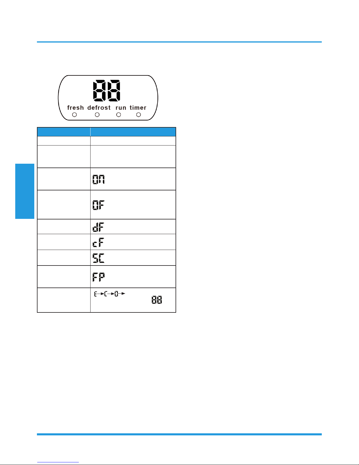
1.3 Display Function
Unit display functions
Function Display
Temperature Set temperature value
Temperature
(fan and Drying
mode)
Room temperature
Activation of Timer
ON, Fresh, Swing,
Turbo, or Silent
(3s)
Cancellation of
Timer OFF, Fresh,
Swing, Turbo, or
Silent
(3s)
Defrost
Warming in heating
mode
Self-clean (available
on select units only)
Heating in room
tempurature
under 8°C
ECO function
(available on select
units only)
set temperature
gradually illumninates to
in
one second interval
1.4 Fan Mode
When fan mode is activated:
• The outdoor fan and compressor are stopped.
• Temperature control is disabled and no temperature
setting is displayed.
• The indoor fan speed can be set to high, med, low, or
auto.
• The louver operations are identical to those in cooling
mode.
• Auto fan: In fan-only mode, AC operates the same as
auto fan in cooling mode with the temperature set at
24°C.
1.5 Cooling Mode
1.5.1 Compressor Control
∆T is the programmed parameter of temperature
compensation.
• When T1-Ts < ∆T- 2 ℃, the compressor ceases
operation.
• When T1-Ts > ∆T-0.5℃, the compressor continues
operation.
• When the AC is operating in mute mode, the
compressor operates at a low frequency.
• When the current exceeds the preset value, the current
protection function activates and the compressor
ceases operation.
1.5.2 Indoor Fan Control
• In cooling mode, the indoor fan operates continuously.
The fan speed can be set to high, medium, low, or
auto.
• If the compressor ceases operations when the
configured temperature is reached, the indoor fan
motor operates at the minimum or configured speed.
1.5.3 Outdoor Fan Control
• The outdoor unit will be run at different fan speed
according to T4.
• For different outdoor units, the fan speeds are
different.
1.5.4 Condenser Temperature Protection
When condenser temperature is more than setting value,
the compressor will stop.
1.5.5 Evaporator Temperature Protection
When evaporator temperature drops below a configured
value, the compressor and outdoor fan ceases operations.
1.6 Heating Mode
1.6.1 Compressor Control
∆T is the programmed parameter of temperature
compensation.
• When T1-Ts>-∆T, the compressor ceases operation.
• When T1-TS<∆T-1.5°C, the compressor continues
operation.
• When the AC is operating in mute mode, the
compressor operates at a low frequency.
• When the current exceeds the preset value, the current
protection function activates and the compressor
ceases operation.

Product Features
Page 11
1.6.2 Indoor Fan Control:
• When the compressor is on, the indoor fan can be set
to high/med/low/auto.
• When indoor unit coil temperature is low, the anti-cold
air function will start and indoor fan motor will run
at low speed, the speed can’t be changed ,when the
temperature is lower than setting value, the indoor fan
motor will stop.
• When the indoor temperature reaches the setting
temperature, the compressor will stop, the indoor
fan motor will run at the minimum speed or setting
speed.(The anti-cold air function is valid).
1.6.3 Outdoor Fan Control:
• The outdoor unit will be run at different fan speed
according to T4.
• For different outdoor units, the fan speeds are
different.
1.6.4 Defrosting mode
• The unit enters defrosting mode according to
changes in the temperature value of T3 as well as the
compressor running time.
• In defrosting mode, the compressor continues to run,
the indoor and outdoor motor will cease operation,
the defrost light of the indoor unit will turn on, and
the “ ” symbol is displayed.
• If any one of the following conditions is satisfied,
defrosting ends and the machine switches to normal
heating mode:
• T3 rises above TCDE1°C.
• T3 maintained above TCDE2°C for 80 seconds.
• Unit runs for 15 minutes consecutively in defrosting
mode.
1.6.5 Evaporator Temperature Protection
When the evaporator temperature exceeds a preset
protection value, the compressor stops.
1.7 Auto-mode
• This mode can be selected with the remote controller
and the setting temperature can be changed between
17°C~30°C.
• In auto mode, the machine selects cooling, heating, or
fan-only mode on the basis of ∆T (∆T =T1-Ts).
∆T Running mode
∆T>2℃ Cooling
-2℃≤∆T≤2℃ Fan-only
∆T<-2℃ Heating*
Heating*: In auto mode, cooling only models run the fan
• The louver operates same as in relevant mode.
• If the machine switches mode between heating and
cooling, the compressor will keep stopping for certain
time and then choose mode according to T1-Ts.
• If the setting temperature is modified, the machine will
choose running function again.
1.8 Drying mode
• Indoor fan speed is fixed at breeze and can’t be
changed. The louver angle is the same as in cooling
mode.
• All protections are active and the same as that in
cooling mode.
1.9 Forced operation function
• Forced cooling mode:
The compressor and outdoor fan continue to run and
the indoor fan runs at low speed. After running for 30
minutes, the AC will switch to auto mode with a preset
temperature of 24°C.
• Forced auto mode:
Forced auto mode operates the same as normal auto mode
with a preset temperature of 24°C.
• The unit exits forced operation when it receives the
following signals:
• Switch on
• Switch off
• Timer on
• Timer off
• Changes in:
• mode
• fan speed
• sleeping mode
• Follow me
1.10 Timer function
• Timing range is 24 hours.
• Timer on. The machine will turn on automatically
when reaching the setting time.
• Timer off. The machine will turn off automatically
when reaching the setting time.
• Timer on/off. The machine will turn on
automatically when reaching the setting “on” time,
and then turn off automatically when reaching the
setting “off” time.

Product Features
Page 12
• Timer off/on. The machine will turn off
automatically when reaching the setting “off” time,
and then turn on automatically when reaching the
setting “on” time.
• The timer function will not change the AC current
operation mode. Suppose AC is off now, it will not
start up firstly after setting the “timer off” function.
And when reaching the setting time, the timer LED
will be off and the AC running mode has not been
changed.
• The setting time is relative time.
• The AC will quit the timer function when it has
malfunction
1.11 Economy function
• The sleep function is available in cooling, heating or
auto mode.
• Operation process in sleep mode is as follow:
• When cooling, the setting temperature rises 1℃ (be
lower than 30℃) every one hour, 2 hours later the
setting temperature stops rising and the indoor fan
is fixed at low speed.
• When heating, the setting temperature decreases
1℃ (be higher than 17℃) every one hour, 2 hours
later the setting temperature stops rising and indoor
fan is fixed at low speed. (Anti-cold wind function
has the priority).
• Operation time in sleep mode is 7 hours. After 7 hours
the AC quits this mode and turns off.
• Timer setting is available.
1.12 Auto-Restart function
• The indoor unit has an auto-restart module that
allows the unit to restart automatically. The module
automatically stores the current settings (not including
the swing setting) and, in the case of a sudden power
failure, will restore those setting automatically within 3
minutes after power returns.
• If the unit was in forced cooling mode, it will run in
this mode for 30 minutes and turn to auto mode with
temperature set to 24°C.
• If there is a power failure while the unit is running, the
compressor starts 3 minutes after the unit restarts. If
the unit was already off before the power failure, the
compressor starts 1 minute after the unit restarts.
1.13 Refrigerant Leakage Detection
With this new technology, the display area will show “EC”
when the outdoor unit detects refrigerant leakage.
1.14 Louver Position Memory Function
When starting the unit again after shutting down, its
louver will restore to the angle originally set by the user,
but the precondition is that the angle must be within
the allowable range, if it exceeds, it will memorize the
maximum angle of the louver. During operation, if the
power fails or the end user shuts down the unit in the
turbo mode, the louver will restore to the default angle.
1.15 8°C Heating(Optional)
In heating mode, the temperature can be set to as low
as 8°C, preventing the indoor area from freezing if
unoccupied during severe cold weather.
1.16 Self clean(Optional)
• If you press “Self Clean” when the unit is in cooling or
drying mode:
• For cooling models, the indoor unit will run in low
fan mode for a certain time, then ceases operation.
• For heat pump models, the indoor unit will run in
fan-only mode, then low heat, and finally in fanonly mode.
• Self Clean keeps the indoor unit dry and prevents
mold growth.
1.17 Follow me(Optional)
• If you press “Follow Me” on the remote, the indoor
unit will beep. This indicates the follow me function is
active.
• Once active, the remote control will send a signal
every 3 minutes, with no beeps. The unit automatically
sets the temperature according to the measurements
from the remote control.
• The unit will only change modes if the information
from the remote control makes it necessary, not from
the unit’s temperature setting.
• If the unit does not receive a signal for 7 minutes or
you press “Follow Me,” the function turns off. The
unit regulates temperature based on its own sensor
and settings.
1.18 Silence (Optional)
Press “Silence” on the remote control to enable the
SILENCE function. While this function is active, the
compressor frequency is maintained at a lower level than
F2. The indoor unit will run at faint breeze, which reduces
noise to the lowest possible level.

Product Features
Page 13
1.19 Information Inquiry
• To enter information inquiry status, complete the following procedure within ten seconds:
• Press LED 3 times.
• Press SWING 3 times.
• If you are successful, you will hear beeps for two seconds.
• Use the LED and SWING buttons to cycle through information displayed.
• Pressing LED will display the next code in the sequence. Pressing SWING will show the previous.
• The table next shows information codes. The screen will display this code for two seconds, then the information for
25 seconds.

Product Features
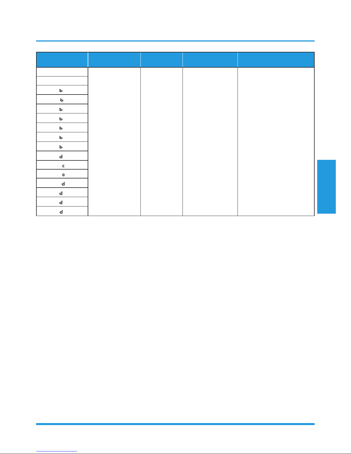
Page 14
Displayed code Explanation
Displayed
value
Meaning Additional Notes
T1
T2
T3
T4
Tb
TP
TH
FT
Fr
Room temperature
-1F,-1E,-1d,-1c,1b,-1A
-19—99
A0,A1,…A9
b0,b1,…b9
c0,c1,…c9
d0,d1,…d9
E0,E1,…E9
F0,F1,…F9
-25,-24,-23,-22,
-21,-20
-19—99
100,101,…109
110,111,…119
120,121,…129
130,131,…139
140,141,…149
150,151,…159
1. All displayed temperatures
use actual values.
2. All temperatures are
displayed in °C regardless
of remote used.
3. T1, T2, T3, T4, and T2B
display ranges from -25 to
70 °C. TP display ranges
from -20 to 130 °C.
4. The frequency display
ranges from 0 to 159HZ.
5. If the actual values exceed
or fall short of the defined
range, the values closest
to the maximum and
minimum values will be
displayed.
Indoor coil
temperature
Outdoor coil
temperature
Ambient
temperature
Outlet temperature
of indoor coil
Discharge
temperature
Suction temperature
Targeted frequency
Actual frequency
IF
Indoor fan speed
0
1,2,3,4
14-FF
OFF
Low speed, Medium
speed, High speed,
Turbo.
Actual fan speed is
equal to the display
value converted to
decimal value and
multiplied by 10. This
is measured in RPM.
N/A
Used for some large capacity
motors.
Used for some small capacity
motors.
The display value is 14-FF
(hexadecimal). The
corresponding fan speed
ranges from 200 to 2550RPM.
OF
Outdoor fan speed
LA
EXV opening angle 0-FF
Actual EXV opening
value is equal to
the display value
converted to decimal
value and then
multiplied by 2.
-
CT
Compressor
continuous running
time
0-FF 0-255 minutes
If the actual value exceeds
or falls short of the defined
range, the value closest to the
maximum and minimum will
be displayed.
ST
Causes of
compressor stop
0-99
For a detailed
explanation, contact
technical support.
-
Product Features
Page 15
Displayed code Explanation
Displayed
value
Meaning Additional Notes
A0
Reserved
0-FF
2-28
5-20
5-25
- -
A1
0
1
2
3
4
5
6
L
A
U
T
A
5
T

Contents
1. Maintenance ........................................................................................................17
1.1 First Time Installation Check ........................................................................17
1.2 Refrigerant Recharge ...................................................................................19
1.3 Re-Installation .............................................................................................20
1.3.1 Indoor Unit ..................................................................................20
1.3.2 Outdoor Unit ...............................................................................22
2. Disassembly .........................................................................................................24
2.1 Indoor Unit ..................................................................................................24
2.2 Outdoor Unit ...............................................................................................40
Maintenance and Disassembly
Maintenance and
Disassembly
Page 17
1. Maintenance
1.1 First Time Installation Check
Air and moisture trapped in the refrigerant system affects
the performance of the air conditioner by:
• Increasing pressure in the system.
• Increasing the operating current.
• Decreasing the cooling or heating efficiency.
• Congesting the capillary tubing due to ice build-up in
the refrigerant circuit.
• Corroding the refrigerant system.
To prevent air and moisture from affecting the air
conditioner’s performance, the indoor unit, as well as the
pipes between the indoor and outdoor unit, must be be
leak tested and evacuated.
Leak test (soap water method)
Use a soft brush to apply soapy water or a neutral liquid
detergent onto the indoor unit connections and outdoor
unit connections. If there is gas leakage, bubbles will form
on the connection.
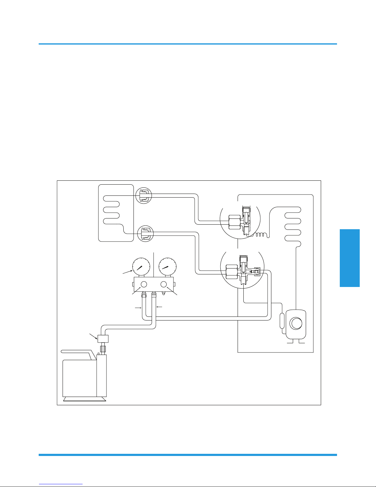
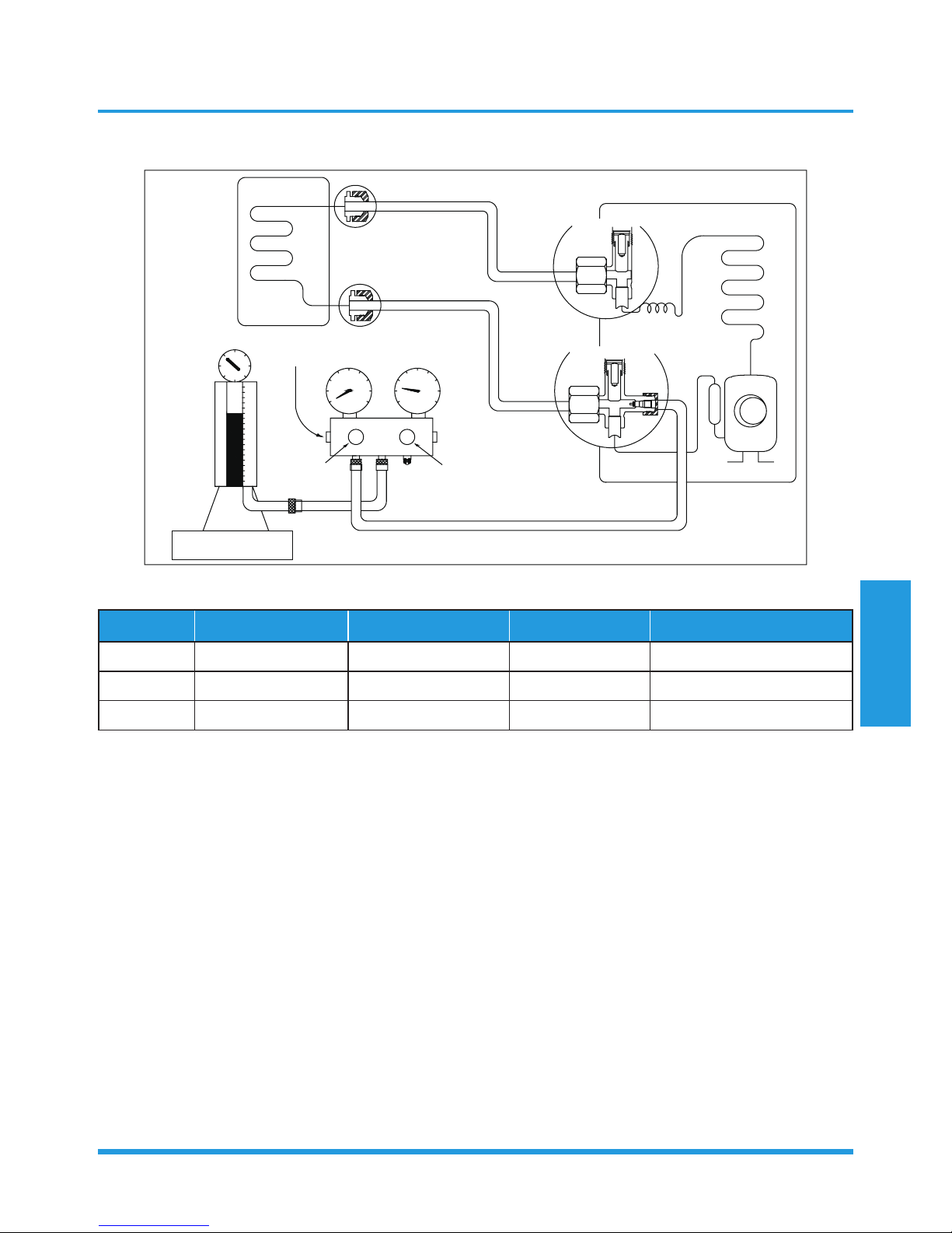
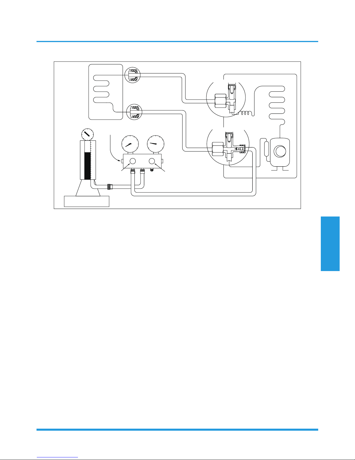
Air purging with vacuum pump
/TJUUX[TOZ
2OW[OJYOJK
-GYYOJK
:]U]G_\GR\K
:NXKK]G_\GR\K
5[ZJUUX[TOZ
)RUYK
)RUYK
3GTOLURJ\GR\K
36G
6XKYY[XK
MG[MK
.GTJRK2U
.GTJRK.O
)NGXMKNUYK
)NGXMKNUYK
<GI[[S
V[SV
<GI[[S
V[SV
)USVU[TJSKZKX
2U
.O

Maintenance and
Disassembly
Page 18
Procedure:
1. Tighten the flare nuts of the indoor and outdoor
units, and confirm that both the 2- and 3-way valves
are closed.
2. Connect the charge hose with the push pin of Handle
Lo to the gas service port of the 3-way valve.
3. Connect the charge hose of Handle Hi connection to
the vacuum pump.
4. Fully open the Handle Lo manifold valve.
5. Using the vacuum pump, evacuate the system for
30 minutes.
a. Check whether the compound meter indicates
-0.1 MPa (14.5 Psi).
• If the meter does not indicate -0.1 MPa
(14.5 Psi) after 30 minutes, continue
evacuating for an additional 20 minutes.
• If the pressure does not achieve -0.1 MPa
(14.5 Psi) after 50 minutes, check for leakage.
• If the pressure successfully reaches -0.1 MPa
(14.5 Psi), fully close the Handle Lo valve and
cease vacuum pump operations.
b. Wait for 5 minutes then check whether the gauge
needle moves after turning off the vacuum pump.
6. Loosen the flare nut of the 3-way valve for 6 or
7 seconds and then tighten the flare nut again.
a. Confirm the pressure display in the pressure
indicator is slightly higher than the atmospheric
pressure.
b. Remove the charge hose from the 3-way valve.
7. Fully open the 2- and 3-way valves and tighten the
cap of the 3-way valve.
Maintenance and
Disassembly
Page 19
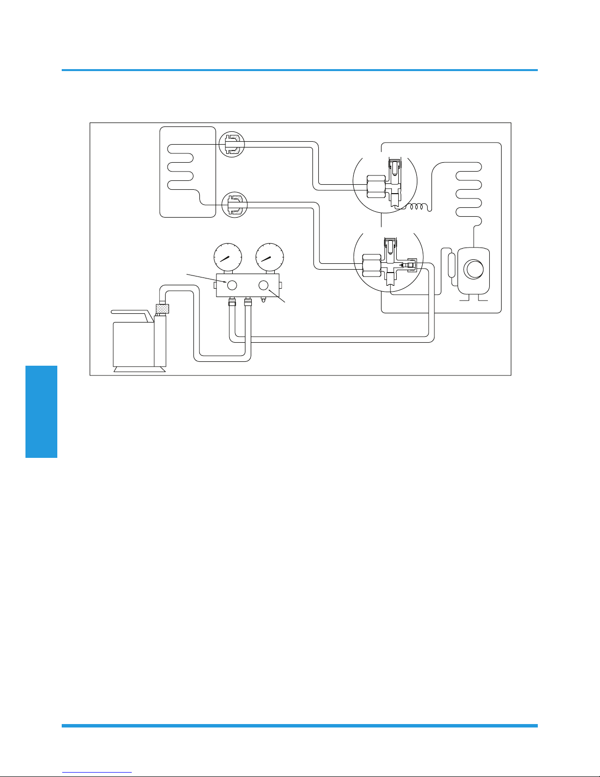
1.2 Refrigerant Recharge
/TJUUX[TOZ
2OW[OJYOJK
-GYYOJK
)NKIQ\GR\K
56+4
)259+
)NGXMOTM
:]U]G_\GR\K
:NXKK]G_\GR\K
5[ZJUUX[TOZ
5VKT
5VKT
2U
.O
+RKIZXUTOIYIGRK
I_ROTJKX
Prior to recharging the refrigerant, confirm the additional amount of refrigerant required using the following table:
Models Standard length Max. elevation Max. length Additional refrigerant
9k&12k 5m (16.4ft) 10m (32.8ft) 25m (82ft) 30g/m (0.32oz/ft)
18k 5m (16.4ft) 20m (65.6ft) 30m (98.4ft) 30g/m (0.32oz/ft)
24k 5m (16.4ft) 25m (82ft) 50m (164ft) 30g/m (0.32oz/ft)
Procedure:
8. Connect the charge hose to the 3-way service port
and then open the 2- and the 3-way valves.
9. Connect the charge hose to the valve at the bottom
of the cylinder.
10. If the refrigerant is R410A, invert the cylinder to
ensure a complete liquid charge.
11. Open the valve at the bottom of the cylinder and close
the check valve on the charge set to purge the air.
12. Place the charging cylinder onto an electronic scale
and record the starting weight.
13. Operate the air conditioner in cooling mode.
14. Open the valves (Low side) on the charge set and
charge the system with liquid refrigerant.
15. When the electronic scale displays the correct weight
(refer to the gauge and the pressure of the low side
to confirm), disconnect the charge hose from the
3-way valve’s service port immediately and turn off
the air conditioner before disconnecting the hose.
16. Mount the valve stem caps and the service port.
17. Use a torque wrench to tighten the service port cap to
a torque of 18 N.m.
18. Check for gas leakage.
Maintenance and
Disassembly
Page 20
1.3 Re-Installation
1.3.1 Indoor Unit
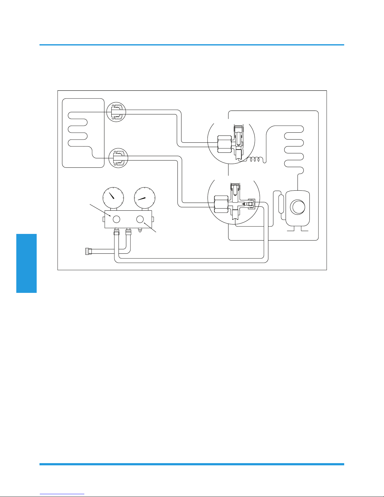
Collecting the refrigerant into the outdoor unit
/TJUUX[TOZ
2OW[OJYOJK
-GYYOJK
)RUYK
)RUYK
:]U]G_\GR\K
:NXKK]G_\GR\K
5[ZJUUX[TOZ
5VKT
)RUYK
2U
.O
Procedure:
19. Confirm that the 2- and 3-way valves are opened.
20. Remove the valve stem caps and ensure that the valve
stems are opened (use as hexagonal wrench to open
the valve stems).
21. Connect the charge hose with the push pin of Handle
Lo to the 3-way valve’s gas service port.
22. Open the Handle Lo valve of the manifold valve to
purge air from the charge hose for 5 seconds and
then close it quickly.
23. Close the 2-way valve.
24. Operate the air conditioner in cooling mode. Cease
operations when the gauge reaches 0.1 MPa
(14.5 Psi).
25. Close the 3-way valve so that the gauge rests
between 0.3 MPa (43.5 Psi) and 0.5 MPa (72.5 Psi).
26. Disconnect the charge set, and tighten the 2- and
3-way valve’s stem nuts (use a torque wrench to
tighten the 3-way valves service port cap to a torque
of 18 N.m).
27. Check for gas leakage.
Maintenance and
Disassembly
Page 21
Air purging with vacuum pump
/TJUUX[TOZ
2OW[OJYOJK
-GYYOJK
:]U]G_\GR\K
:NXKK]G_\GR\K
5[ZJUUX[TOZ
)RUYK
)RUYK
3GTOLURJ\GR\K
36G
6XKYY[XK
MG[MK
.GTJRK2U
.GTJRK.O
)NGXMKNUYK
)NGXMKNUYK
<GI[[S
V[SV
<GI[[S
V[SV
)USVU[TJSKZKX
2U
.O
Procedure:
28. Tighten the flare nuts of the indoor and outdoor
units, and confirm that both the 2- and 3-way valves
are closed.
29. Connect the charge hose with the push pin of Handle
Lo to the gas service port of the 3-way valve.
30. Connect the charge hose of Handle Hi connection to
the vacuum pump.
31. Fully open the Handle Lo manifold valve.
32. Using the vacuum pump, evacuate the system for
30 minutes.
a. Check whether the compound meter indicates
-0.1 MPa (14.5 Psi).
• If the meter does not indicate -0.1 MPa (14.5 Psi)
after 30 minutes, continue evacuating for an
additional 20 minutes.
• If the pressure does not achieve -0.1 MPa
(14.5 Psi) after 50 minutes, check for leakage.
• If the pressure successfully reaches -0.1 MPa
(14.5 Psi), fully close the Handle Lo valve and
cease vacuum pump operations.
b. Wait for 5 minutes then check whether the gauge
needle moves after turning off the vacuum pump.
33. Loosen the flare nut of the 3-way valve for 6 or
7 seconds and then tighten the flare nut again.
c. Confirm the pressure display in the pressure
indicator is slightly higher than the atmospheric
pressure.
d. Remove the charge hose from the 3-way valve.
34. Fully open the 2- and 3-way valves and tighten the
cap of the 3-way valve.
Maintenance and
Disassembly
Page 22
1.3.2 Outdoor Unit
Evacuation for the whole system
/TJUUX[TOZ
2OW[OJYOJK
-GYYOJK
56+4
)259+
:]U]G_\GR\K
:NXKK]G_\GR\K
5[ZJUUX[TOZ
5VKT
5VKT
2U
.O
<GI[[SV[SV
Procedure:
35. Confirm that the 2- and 3-way valves are opened.
36. Connect the vacuum pump to the 3-way valve’s
service port.
37. Evacuate the system for approximately one hour.
Confirm that the compound meter indicates
-0.1 MPa (14.5Psi).
38. Close the valve (Low side) on the charge set and turn
off the vacuum pump.
39. Wait a period of five minutes then check whether the
gauge needle moves after turning off the vacuum
pump.
40. Disconnect the charge hose from the vacuum pump.
Maintenance and
Disassembly
Page 23
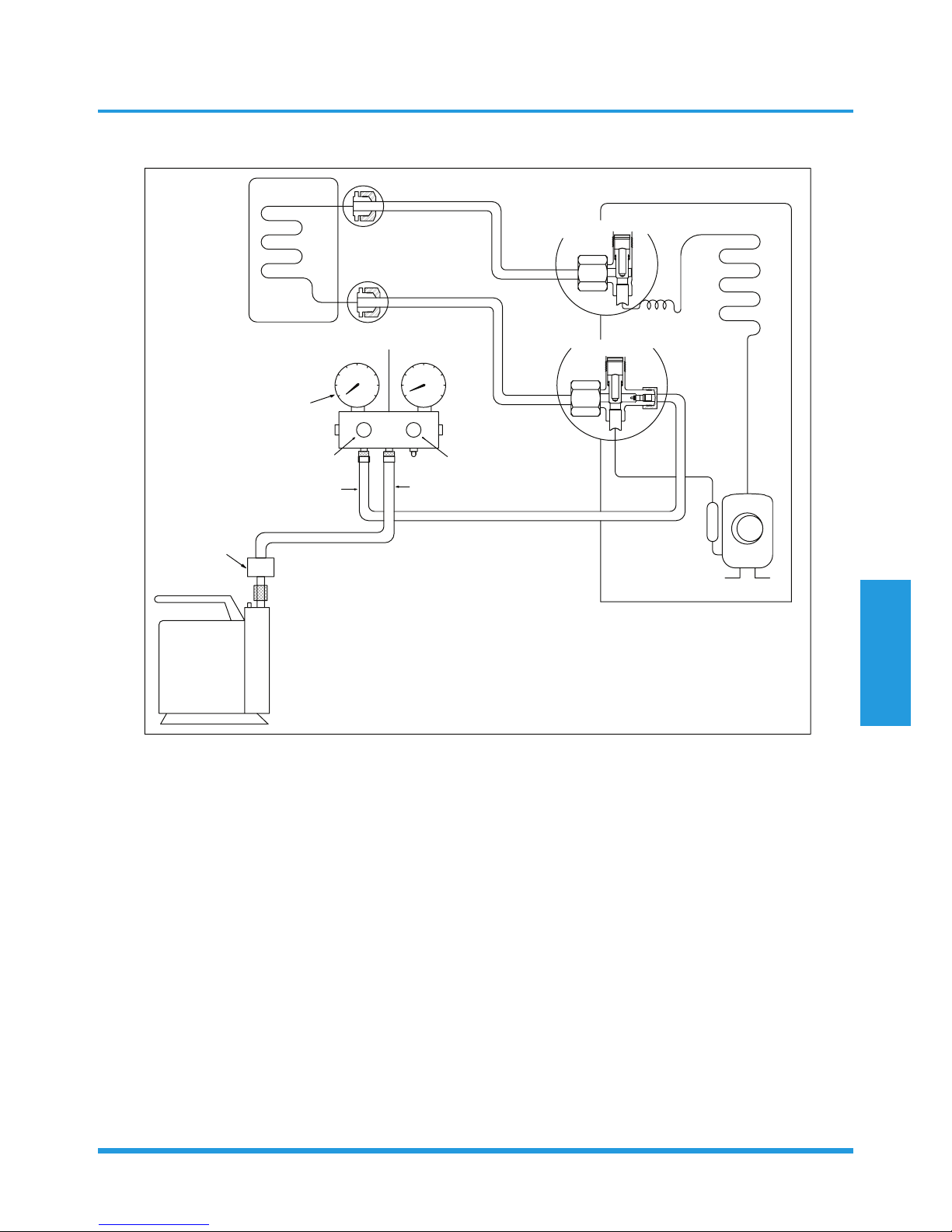
Refrigerant charging
/TJUUX[TOZ
2OW[OJYOJK
-GYYOJK
)NKIQ\GR\K
56+4
)259+
)NGXMOTM
:]U]G_\GR\K
:NXKK]G_\GR\K
5[ZJUUX[TOZ
5VKT
5VKT
2U
.O
+RKIZXUTOIYIGRK
I_ROTJKX
Procedure:
41. Connect the charge hose to the 3-way service port
and then open the 2- and the 3-way valves.
42. Connect the charge hose to the valve at the bottom
of the cylinder.
43. If the refrigerant is R410A, invert the cylinder to
ensure a complete liquid charge.
44. Open the valve at the bottom of the cylinder and close
the check valve on the charge set to purge the air.
45. Place the charging cylinder onto an electronic scale
and record the starting weight.
46. Operate the air conditioner in cooling mode.
47. Open the valves (Low side) on the charge set and
charge the system with liquid refrigerant.
48. When the electronic scale displays the correct weight
(refer to the gauge and the pressure of the low side
to confirm), disconnect the charge hose from the
3-way valve’s service port immediately and turn off
the air conditioner before disconnecting the hose.
49. Mount the valve stem caps and the service port.
50. Use a torque wrench to tighten the service port cap to
a torque of 18 N.m.
51. Check for gas leakage.
Note: 1. Mechanical connectors used indoors shall comply with local regulations.
2. When mechanical connectors are reused indoors, sealing parts shall be renewed. When flared joints
are reused indoors, the flare part shall be re-fabricated.
Maintenance and
Disassembly
Page 24
2. Disassembly
2.1 Indoor unit
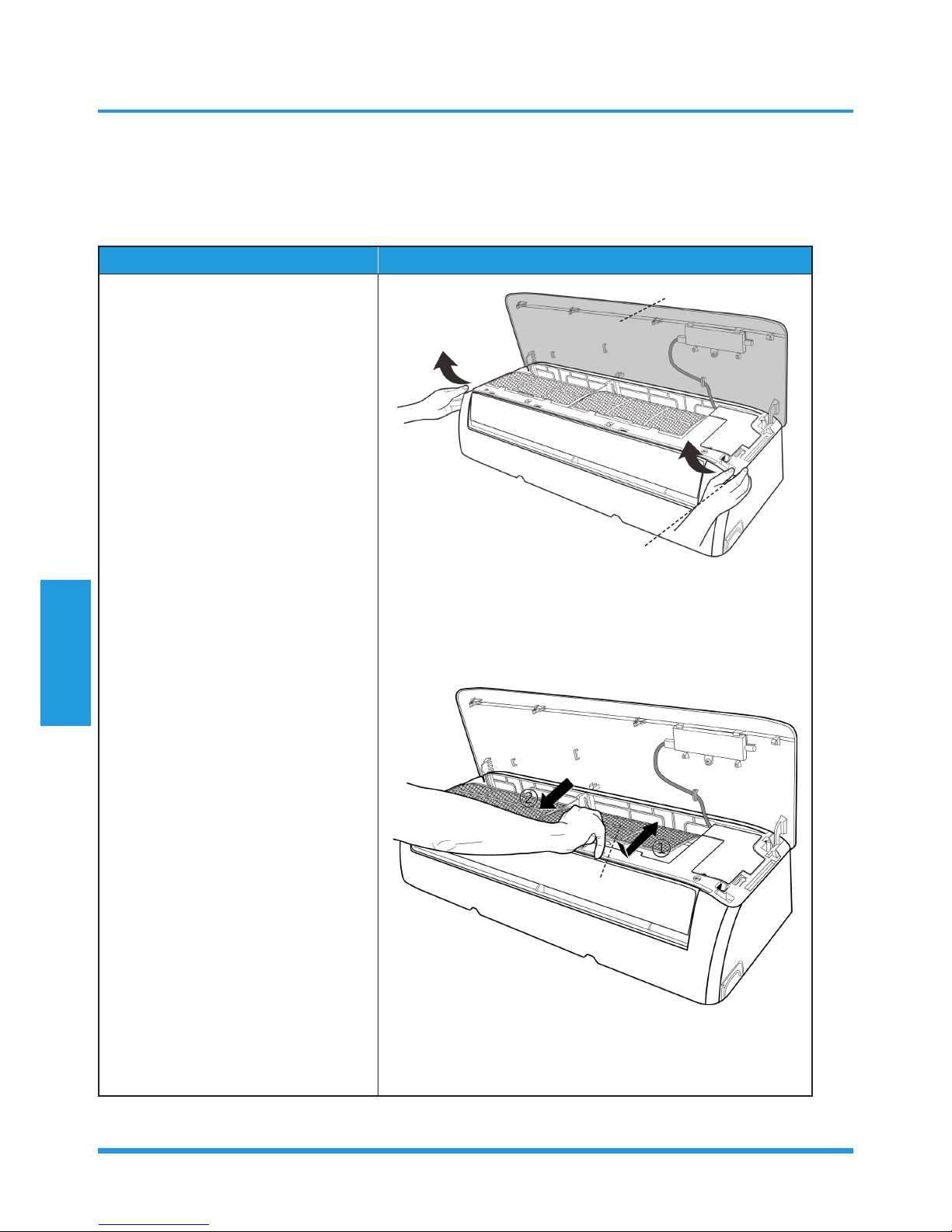
1. Front Panel
Procedure Illustration
1) Hold the front panel by the tabs on
the both sides and lift it (see CJ_AB_
INV_001).
2) Push up the bottom of an air
filter (step 1), and then pull it out
downwards (step 2) (see CJ_AB_
INV_002).
CJ_AB_INV_001
CJ_AB_INV_002
Note: This section is for reference only. Actual unit appearance may vary.
Front Panel
Tab
Filter
Maintenance and
Disassembly
Page 25
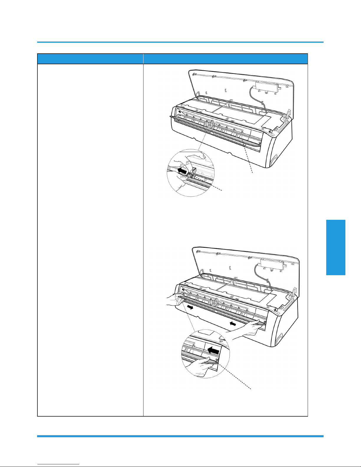
Procedure Illustration
3) Open the horizontal louver and push
the hook towards left to open it (see
CJ_AB_INV_003).
4) Bend the horizontal louver lightly by
both hands to loosen the hooks, then
remove the horizontal louver (see
CJ_AB_INV_004).
CJ_AB_INV_003
CJ_AB_INV_004
Note: This section is for reference only. Actual unit appearance may vary.
Hook
Horizontal Louver
Hook
 Loading...