

Page 1
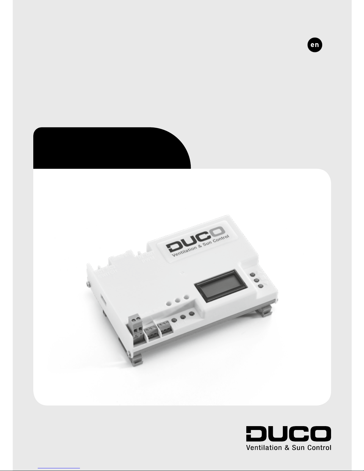
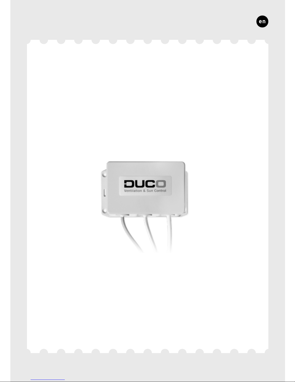
IQ-unit
Quick Start
L1020200-D 21.06.2017
ENGLISH
Page 2
DUCO, HANDELSSTRAAT 19
VEURNE, B8630
09
Raadpleeg www.duco.eu voor meer informatie omtrent garantie, onderhoud,
technische gegevens enz.
Installatie, aansluiting, onderhoud en herstellingen dienen door een erkend
ins
tallateur te gebeuren. De elektronische onderdelen van dit product kunnen
onder spanning staan. Vermijd contact met water.
Naviguez vers www.duco.eu pour plus d’informations sur la garantie, l’entretien,
des fiches techniques etc.
L’installation, le raccordement, l’entretien et les réparations doivent être effectués
par un ins
tallateur agréé. Les éléments électroniques de ce produit peuvent être
sous tension. Éviter tout contact avec l’eau.
See www.duco.eu for information regarding warranty, maintenance, technical data,
etc.
Installation, connection, maintenance and repairs are to be carried out by an
accredited installer. The electronic components of this product may be live. Avoid
contact with water.
Page 3

75
ENGLISH
Table of contents
1 Application ...................................................................................................................................................76
Centrally controlled exhaust
..............................................................................................77
Zonally controlled exhaust
....................................................................................................78
2
Connectors and buttons ................................................................................................................79
3
Cabling .............................................................................................................................................................81
Cabling diagram
..............................................................................................................................82
RF (wireless communication)
............................................................................................84
Wired (cabled communication)
.........................................................................................85
Various cabling options
............................................................................................................86
4
Installation ..................................................................................................................................................88
Mounting
.................................................................................................................................................88
Air duct connections
...................................................................................................................89
5
Zonal control options .......................................................................................................................90
6
Installation ..................................................................................................................................................92
Installer / User mode
.................................................................................................................92
Installing components
...............................................................................................................94
Other operations
.............................................................................................................................98
7
Configuration ............................................................................................................................................99
Setting exhaust vents
.................................................................................................................99
Configuration
...................................................................................................................................102
8
Settings ....................................................................................................................................................... 106
Setting the time
.............................................................................................................................108
NightBoost
..........................................................................................................................................109
ModBus
..................................................................................................................................................110
Page 4

76
ENGLISH
The IQ-unit operates as a ‘master’ or brain within Duco's Demand-Controlled Natural Ventilation Systems.
It receives and interprets signals from the ‘slave’ components (measurements from a sensor or manual input), based on which it controls
the ventilation system and any external unit. The IQ-unit thus ensures
that stale air, with excessive CO2 or moisture content, is exhausted.
The IQ-unit boasts smart functions such as NightBoost and ventilative
cooling, and can also be connected to a building management system
via ModBus.
The IQ-unit can be used in different situations and can perform different functions depending on requirements and the type of central
extract unit:
DucoBox WTW
The IQ-unit controls the DucoBox WTW via the WTW connection.
Pressure-controlled fan
With this the IQ-unit is not connected to the central extract unit. In this
case, the IQ-unit is only required to utilise functions such as ModBus,
NightBoost and ventilative cooling.
Non-pressure-controlled fan
The IQ-unit controls the fan via a PWM connection.
With the IQ-unit, both centrally and zonally controlled exhaust is
available.
1
Application
Page 5
77
ENGLISH
*
PWM
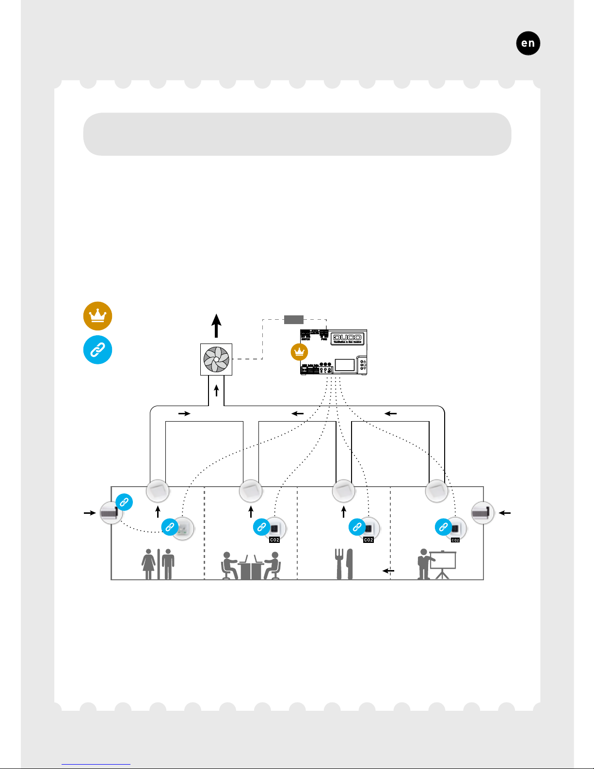
With centrally (= not locally) controlled exhaust, air is exhausted in
every air duct connected.
1A.
Centrally controlled exhaust
Master
Slave
* Connection between IQ-unit and fan (via PWM) is only applicable when using a non-pressure-
controlled fan.
Page 6
78
ENGLISH
1B.
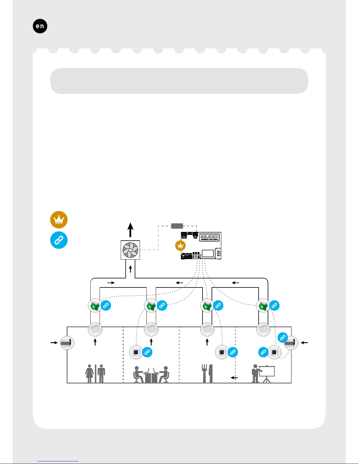
Zonally controlled exhaust
With zonally (= locally) controlled exhaust, stale air is exhausted only
where necessary, which is conducive to optimum energy-efficiency and
quietness in the ventilation system. This requires a component to be
provided for each zone that acts as a control valve to regulate the exhaust air flow rate in that zone. This can be done by providing an Intelli
Air Valve — Duco’s smart control valve — in the duct of each zone, or
using another component with actuator control if the maximum flow
rate through an Intelli Air Valve is insufficient, such as a DucoGrille
Close.
PWM
*
Master
Slave
* Connection between IQ-unit and fan (via PWM) is only applicable when using a non-pressure-
controlled fan.
Page 7
79
ENGLISH
4
1
5
2
6
3
10
7
A
8
B
C
F
E
D
119
AABBGND
GND
- +
- +
- +
2
Connectors and buttons
Page 8
80
ENGLISH
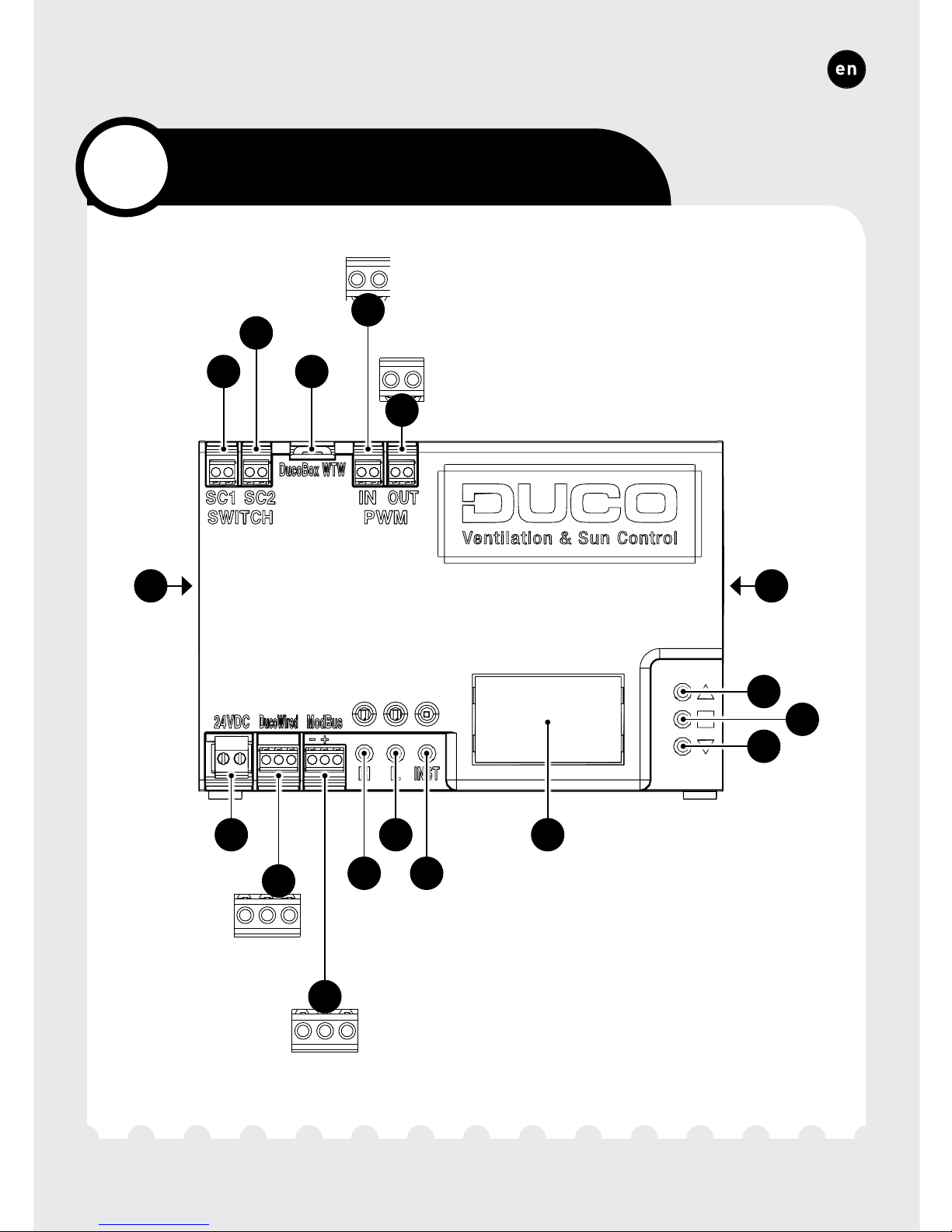
CONNECTORS
1 Power 24 VDC
2 DucoBus (A, B, GND)
3 ModBus (A/-,
B/+, GND)
4 Switch contact 1 -
onboard (n132)
5 Switch contact 2 -
onboard (n133)
6 DucoBox WTW
7 PWM IN
8 PWM OUT
9 Duco Network Tool
BUTTONS
A HIGH
B LOW
C INST
(installer mode)
D UP
E ENTER
F DOWN
DIVERS
10 Display
11 SD card
(software update)
Page 9

81
ENGLISH
The IQ-unit is able to communicate with slave components via a wireless (RF) or wired link. Both types of communication can be combined
in one system. Wired connections are to be recommended in all cases
of non-residential and other projects where large distances or various
walls and/or building levels need to be spanned.
In addition, connections can also be made via a Switch Sensor (quantity
of 2), PWM-IN and PWM-OUT, WTW and ModBus.
3
Cabling
Page 10
82
ENGLISH
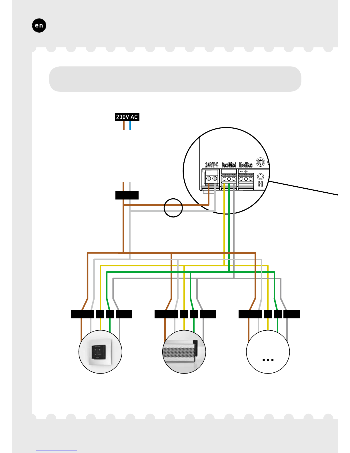
Wired
24 VDC
24 VDC
A B GND
POWER
SUPPLY
User controller
User controller
User controller
Tronicwindow ventilator
Tronicwindow ventilator
Tronicwindow ventilator
24 VDC A B GND 24 VDC A B GND
Not with DucoBox WTW
xxx
xxx
Max. of 99 Wired
3A.
Cabling diagram
Page 11
83
ENGLISH
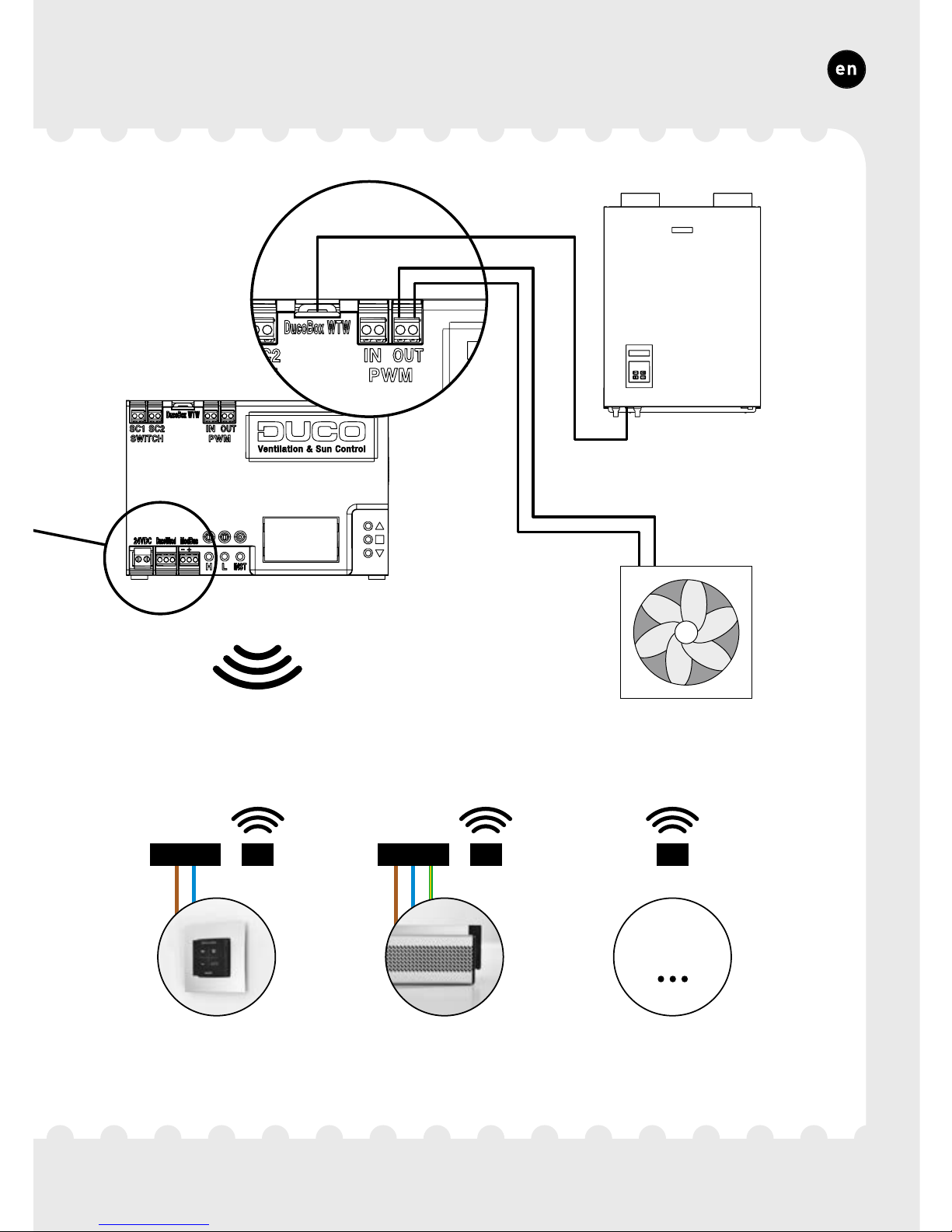
Max. of 30 RF
RF230 VAC
User controller
User controller
User controller
RF230 VAC
Tronic window ventilator
Tronicwindow ventilator
Tronicwindow ventilator
DUCOBOX
WTW
Externalcentral extract
unit
xxx
xxx
OF
OU
OR
RF
RF
Page 12
84
ENGLISH
3B.
RF (wireless communication)
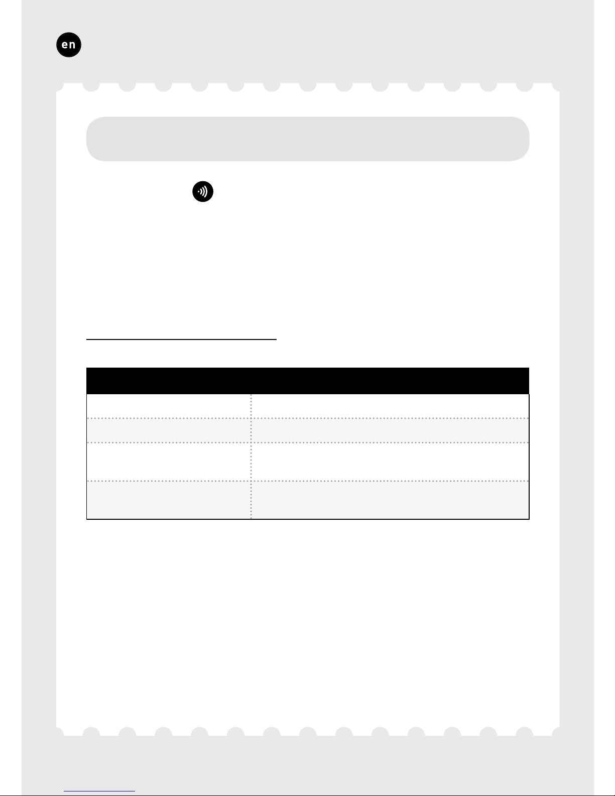
RF components ( ) have a maximum free-field range of 350 metres.
This distance will be much less in a building because of obstacles
so you will need to allow for features such as walls, concrete and
metal. All slave components (except those which are battery powered)
also act as repeaters. Signals from components that are unable to
make a (strong) connection with the master component are forwarded automatically via no more than one other non-battery-powered component (= hop point). Please refer to information sheet
RF communication (L8000001) at www.duco.eu for further information.
DUCO RF
Power supply 230 VAC
Frequency 868 MHz
Maximum distance
350 m, free field
(less through obstacles)
Maximum number
of components
Up to 25 wireless components in a single system
Page 13
85
ENGLISH
3C.
Wired (cabled communication)
Wired components ( ) can be daisy-chained (= recommended). This
means that a separate cable will not be required for each component. A
single central power supply can be used.
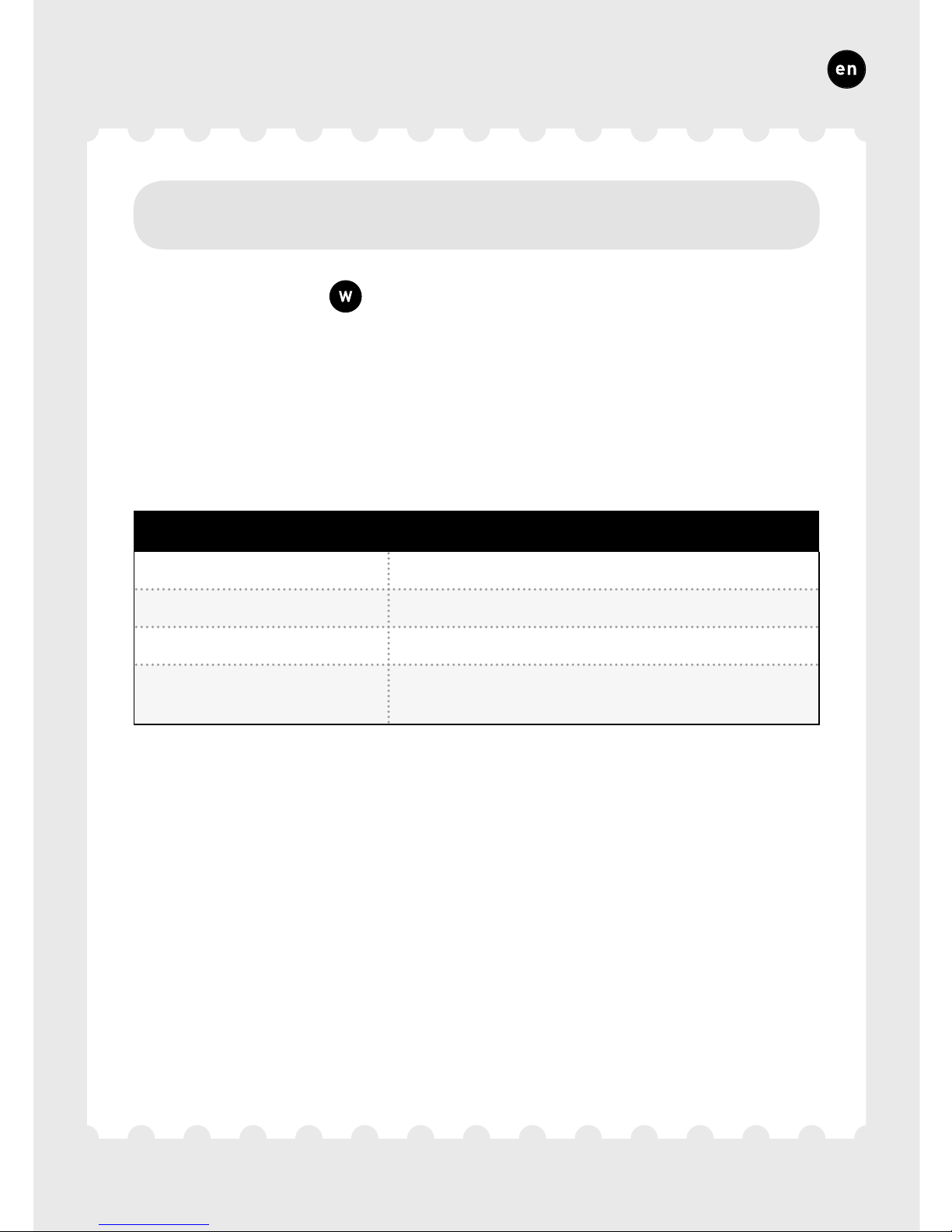
The cable required is a 0.8 mm data cable. We strongly advise using
a shielded cable to prevent any interference that may affect the data
communication.
DUCO WIRED
Power supply 24 VDC
Cabling 3-cores of 0,8mm communication (A, B, GND)
Maximum distance up to 300 m
Maximum number
of components
Up to 99 wired components in a single system
Page 14

86
ENGLISH
3D.
Various cabling options
WTW
Communication with the DucoBox WTW. In this case a separate 24 VDC
is not required for the IQ-unit.
PWM / 0-10V
PWM-OUT enables communication with a central extract unit or an
actuator such as a Variable Air Volume (VAV) valve.
Its operating mode (PWM or 0-10V) can be changed using the display
menu or the Duco Network Tool. It is set to PWM as standard.
PWM-IN enables the IQ-unit to be controlled like an actuator.
An Actuatorprint is required for each actuator to control multiple actuators independently of one another.
ModBus
Communications with building management systems for instance, for
reading out information as well as controlling the ventilation system.
Please refer to information sheet ModBus (L8000009) at www.duco.eu
for more information.
Page 15

87
ENGLISH
Switch Sensor
The Switch Sensor can perform one of the following functions when
closing one contact in a two-pole zero voltage contact (only one function per connection): toilet detection, link to heat pump or overrule
setting. Please refer to information sheet Display menu (L8000015) at
www.duco.eu for more information about its operation.
The contact needs to be closed once in order to pair the component.
Page 16
88
ENGLISH
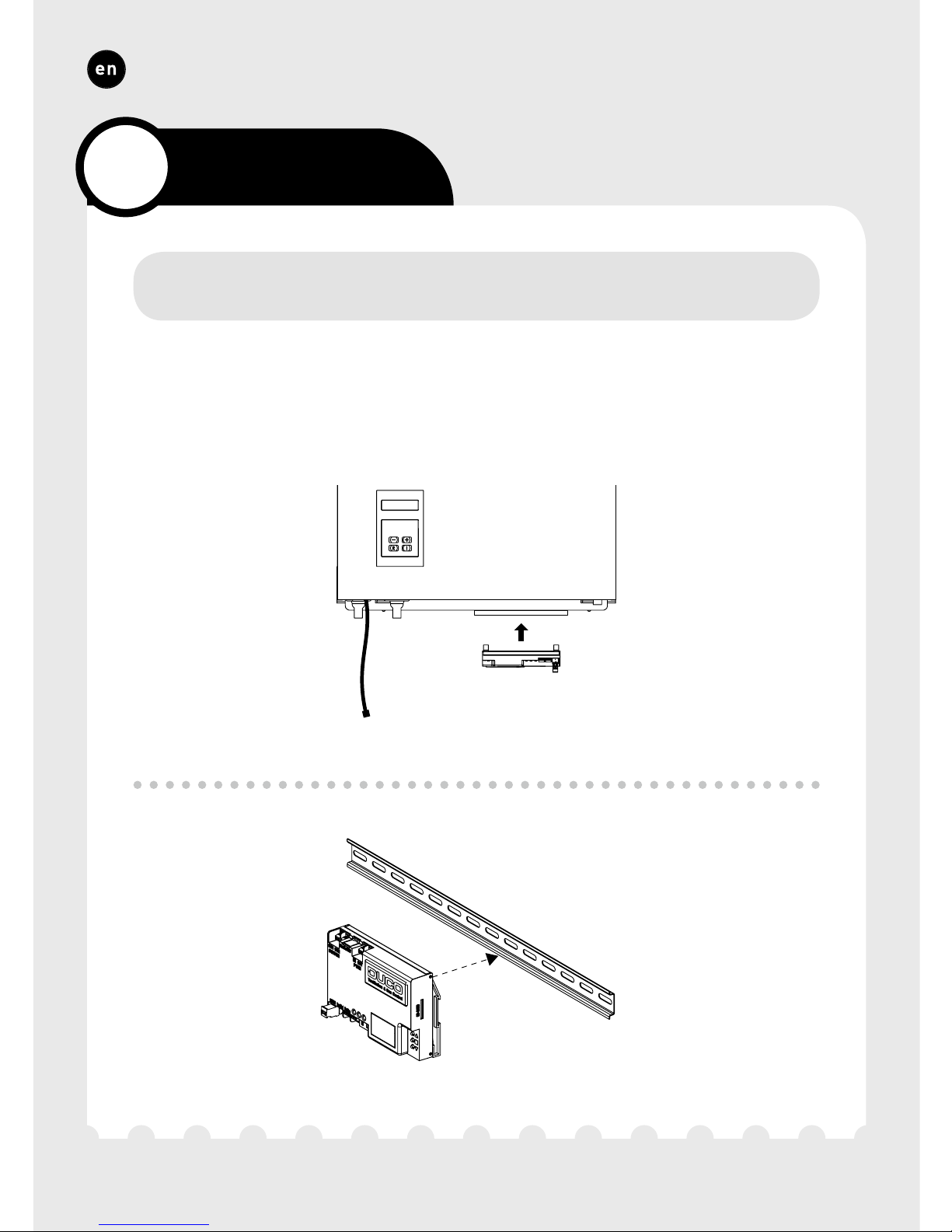
Click the IQ-unit onto the DIN rail underneath the DucoBox WTW or
another DIN rail. Use a screwdriver to “prise” the IQ-unit off the rail.
Din Rail
DucoBox WTW
4
Installation
4A.
Mounting
Page 17
89
ENGLISH
4B.
Air duct connections
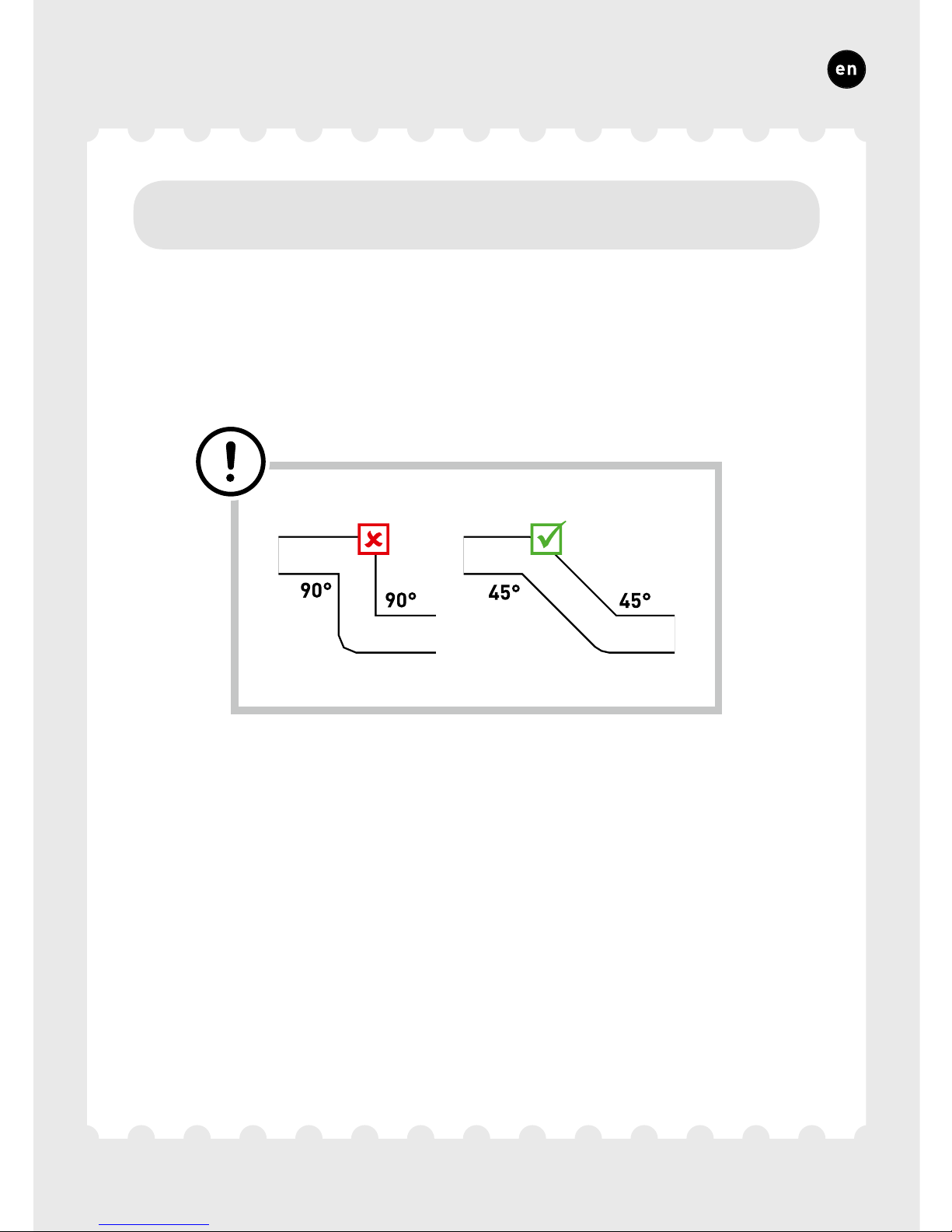
Keep resistance down (especially in the bypass duct). Avoid excessive
use of bends. A non-return flap is required when discharging into a
manifold.
Page 18
90
ENGLISH
In order to enable zonal control, a control valve capable of controlling
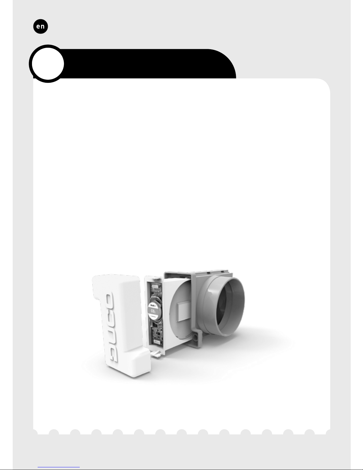
the air exhaust from the zone must be utilised in each zone. This can be
done using an Intelli Air Valve or an actuator via Duco’s Actuatorprint.
Intelli Air Valve
This intelligent control valve uses a wired connection with the IQ-unit
and a wireless (RF) connection with the underlying control components.
The Intelli Air Valve can be easily installed in (existing) ventilation
ducts. Please refer to the manual with the Intelli Air Valve for more
information.
5
Zonal control options
Page 19
91
ENGLISH
Actuator via Duco's Actuatorprint
Actuators can be controlled via Duco’s Actuatorprint. This PCB enables
the IQ-unit to control different actuators separately via a Duco Wired
connection. The Actuatorprint supports PWM, 0-10V, 2 and 3-point
control. The Actuatorprint is available as an external component or is
built into Duco's components such as the DucoGrille Close.
Page 20

92
ENGLISH
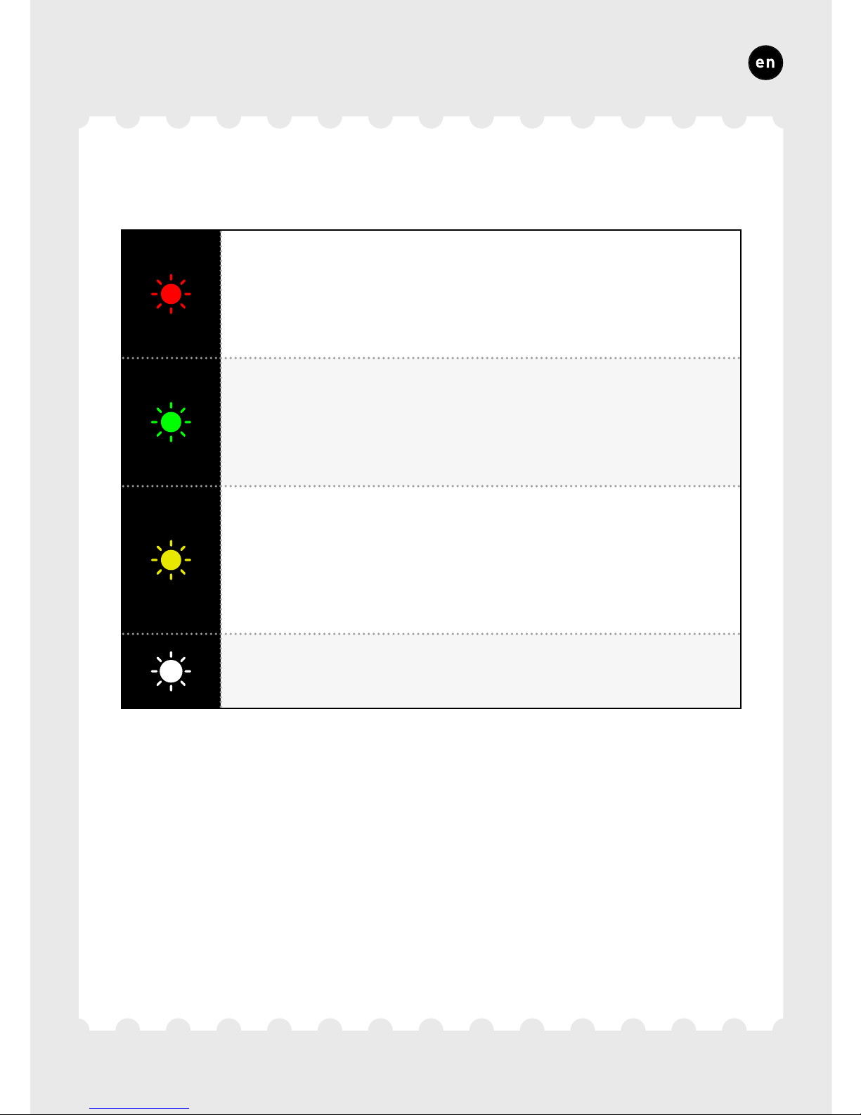
To add, remove or replace components in the network, the system
must be set to ‘Installer mode’. The LED on each component indicates
the active mode of the component (see table below).
‘Installer mode’ can be activated by pressing the IQ-unit ‘INST’ button.
Once the LED on the master unit starts flashing, it means that ‘Installer
mode’ is active. Press ‘INST’ again to return to ‘User mode’ (LED fully
on or off). The system reverts automatically to ‘User mode’ after 15
minutes of inactivity.
6
Installation
6A.
Installer / User mode
Page 21
93
ENGLISH
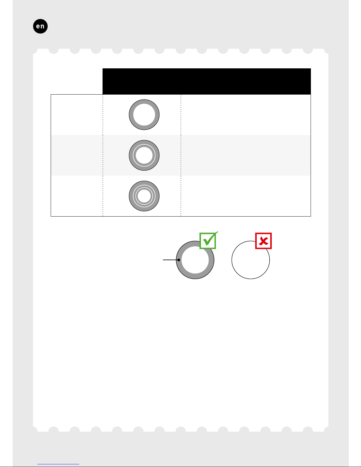
LED INDICATION
RED (flashing slowly)
Not in network
RED (flashing rapidly)
Pairing in progress
GREEN (flashing slowly)
In network
GREEN (flashing rapidly)
In network, waiting for associated components
YELLOW (flashing slowly)
Transfer phase (please wait)
YELLOW (on)
Initialising
(system configuration in progress)
WHITE or OFF
Normal
Page 22
94
ENGLISH
6B.
Installing components
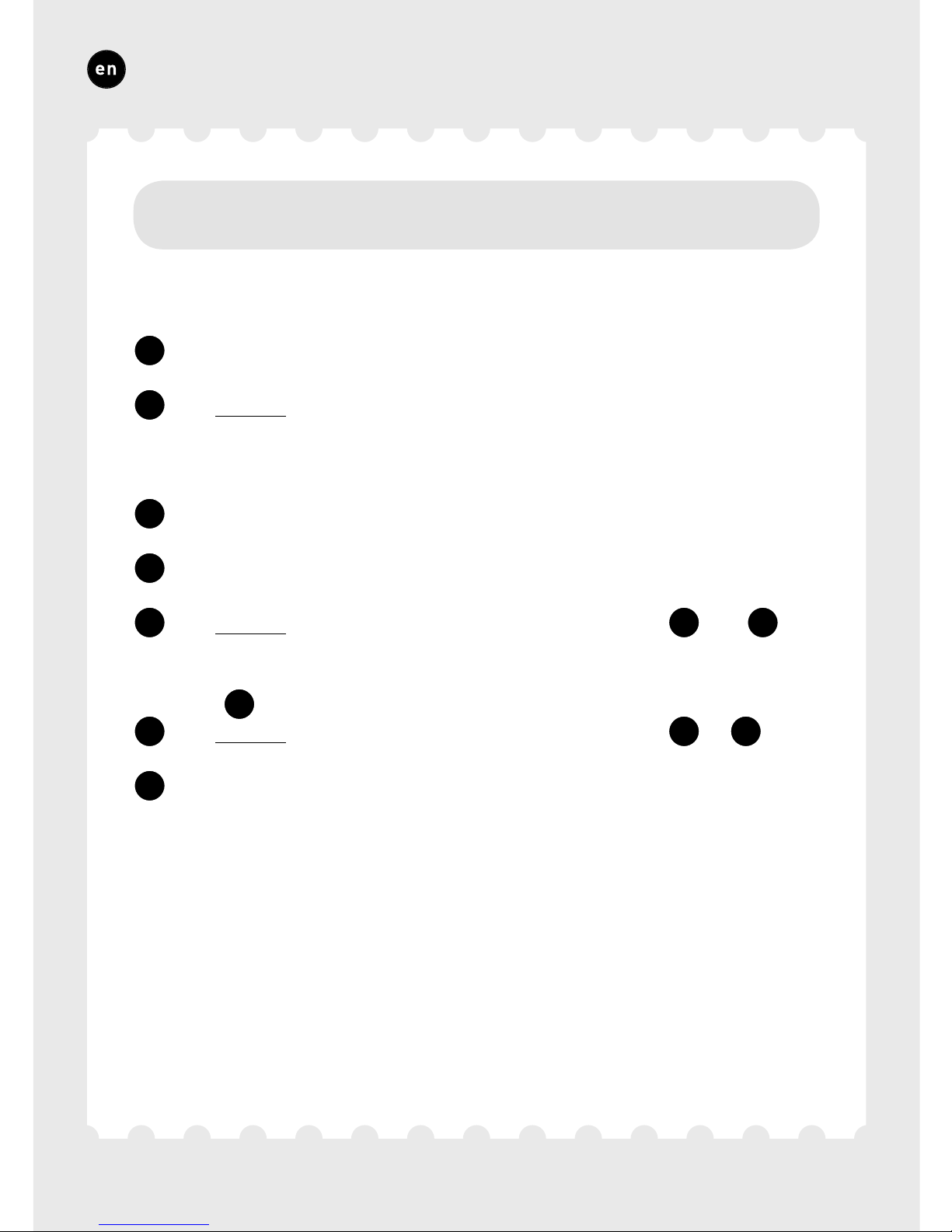
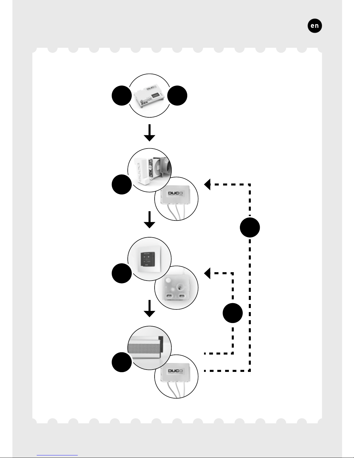
Go through the following steps to pair components with the IQ-unit.
1
Activate ‘Installer mode’ by tapping ‘INST’ on the IQ-unit. The LED
will flash green rapidly.
2
For zonally controlled systems only: Tap once on the feed-through
component to pair it with the IQ-unit so the LED flashes green
slowly. Tap again so the LED starts to flash rapidly. Underlying
components can now be added in this zone.
3
Add control components* by tapping once on the component to be
paired. The LED will start to flash green rapidly.
4
Add any window ventilators* by tapping once on the component to
be paired. The LED will flash green slowly.
5
For zonally controlled systems only: Repeat steps
3
and
4
until all remaining components in the current zone are paired. Exit
the current zone next by tapping the feed-through component from
step
2
once more. The LED will flash green slowly again.
6
For zonally controlled systems only: Repeat steps
2
to
5
inclusive for the remaining zones.
7
Once all components have been paired, ‘Installer mode’ can be
deactivated by tapping ‘INST’ on the IQ-unit.
Please refer to the manual with the components for more detailed
information.
* NB: only RF components can be paired under an Intelli Air Valve.
Page 23
95
ENGLISH
4
2
3
1 7
5
6
Page 24
96
ENGLISH
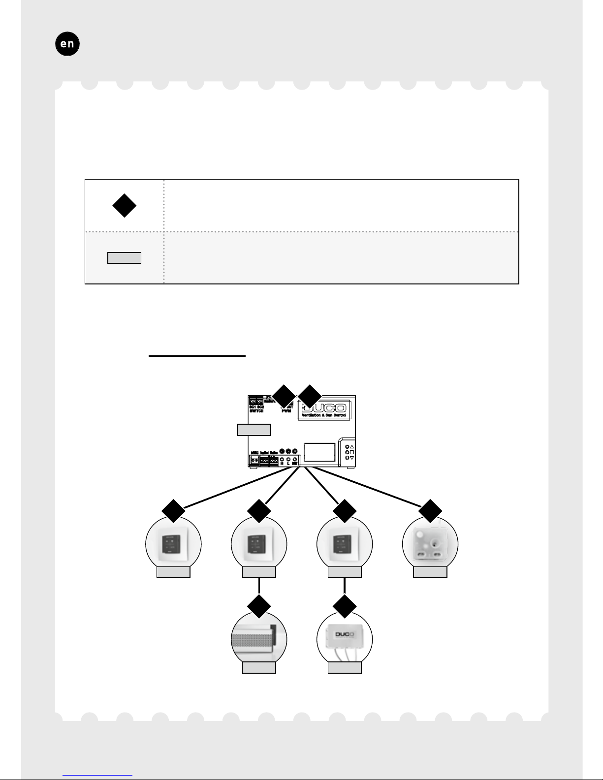
EXAMPLE OF A PAIRING SEQUENCE
centrally controlled exhaust
NODE 2 NODE 3 NODE 5 NODE 7
NODE 4 NODE 6
NODE 1
1
2 3
4
5
6
7
8
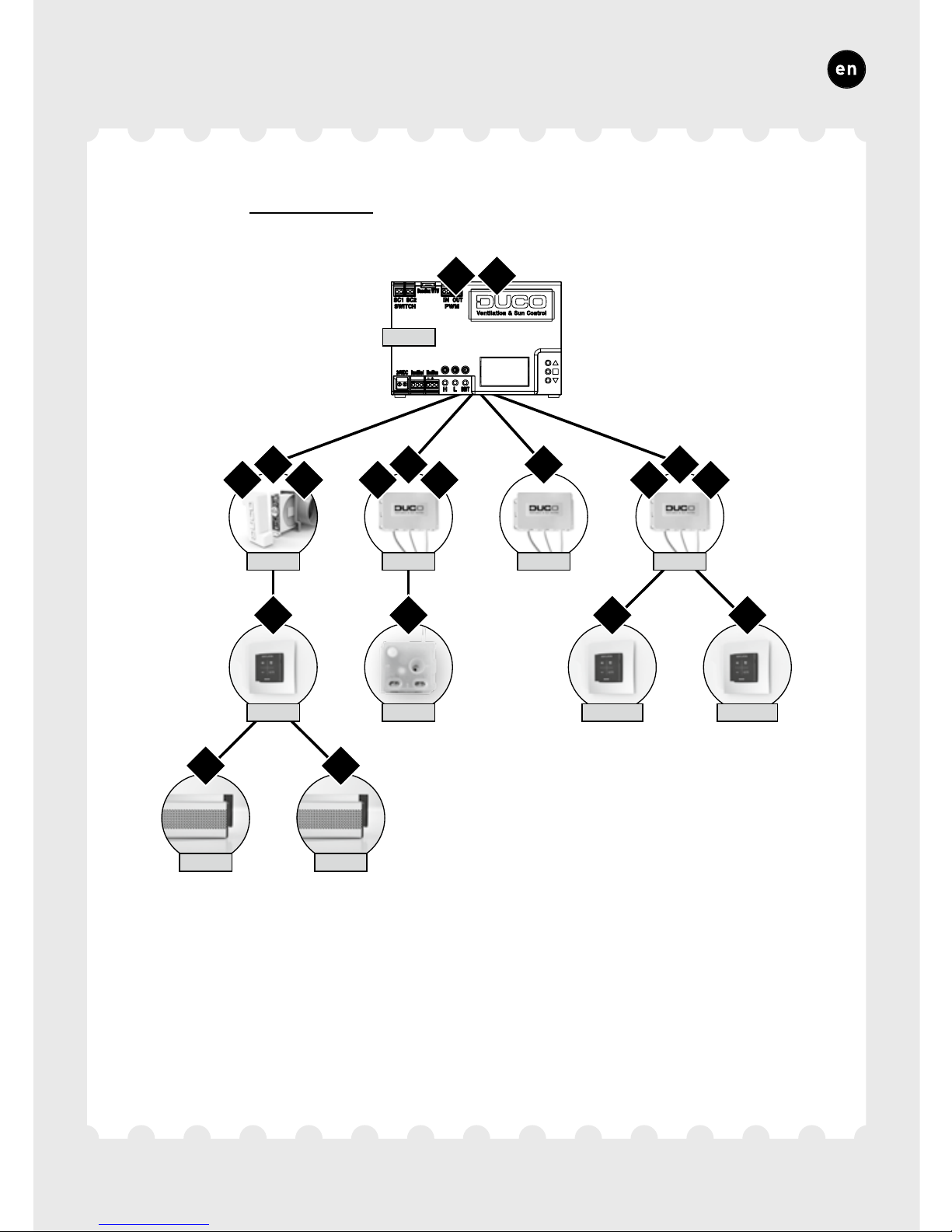
X
indicates the order in which a button of
the component must be pressed.
NODE X
indicates the assigned node number, required for settings in
the display menu (seepage107) and Modbus (see page 110).
Page 25
97
ENGLISH
zonally controlled exhaust
NODE 1
NODE 2 NODE 6 NODE 8 NODE 9
NODE 3 NODE 7
NODE 4 NODE 5
NODE 10 NODE 11
1
9
2
10
3
11
4
12
5
13
6
14
7
15
8
16
17
18
Page 26

98
ENGLISH
6C.
Other operations
Activate ‘Installer mode’ in order to remove or replace a component.
This may be done via the component itself, please refer to the manual
for the component concerned.
Removing a component
Press once and hold the button of the component in order to remove it
from the network.
Replacing a component
Press briefly twice on the button of the component to be removed.
After that, press briefly once on the button of the new component. The
latter will take on all settings/connections within the network.
Tips
In order to remove all components from the network (e.g. in the event
of problems) you can press and hold ‘INST’ until the LED starts flashing red. The IQ-unit will then reboot (around 15 seconds) and the LED
will stop flashing.
Use the Duco Network Tool to read out information from components.
Never pair more than one system with RF components at the same
time.
Page 27

99
ENGLISH
The system needs to be configured for it to work correctly. This will
ensure its operation is as quiet and as energy-efficient as possible.
See under the Tools heading at www.duco.eu for info about determining
ventilation flow rates.
Configuration takes place in two stages: setting exhaust vents and
actual configuration.
The exhaust vents are installed in an exhaust duct for humid/stale air
extraction. For correct configuration, the vents must be set depending
on the exhaust method:
Central exhaust: set the vents to match the desired flow rate in accordance with the following table.
Zonal exhaust: set the vents in accordance with the methods that
follow, depending on the situation in each zone.
When using DucoVent Design, exhaust vents always leave the outer
ring in place for acoustic effect.
7
Configuration
7A.
Setting exhaust vents
Page 28
100
ENGLISH
DUCOVENT
DESIGN
DUCOVENT BASIC
AND OTHER VENTS
75 m³/h
100% open
50 m³/h
50% open
25 m³/h
25% open
Foam
Page 29
101
ENGLISH
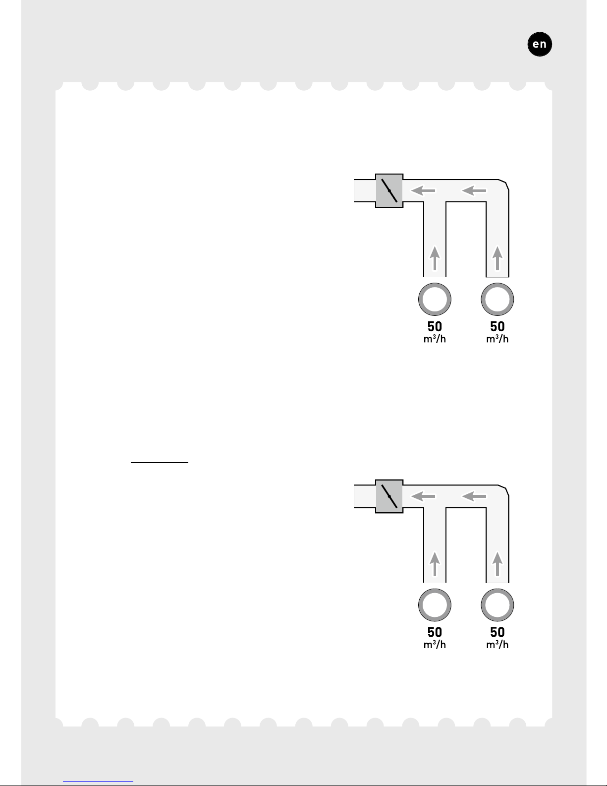
SITUATION 1: one exhaust vent per zone
Set all exhaust vents to the fully
open position, regardless of the
desired flow rate. When using
DucoVent Design exhaust vents,
leave the outer ring in place for
acoustic effect.
SITUATION 2: Multiple exhaust vents per zone
with equal flow rates
Set all exhaust vents to the fully
open position, regardless of the
desired flow rate.
Page 30
102
ENGLISH
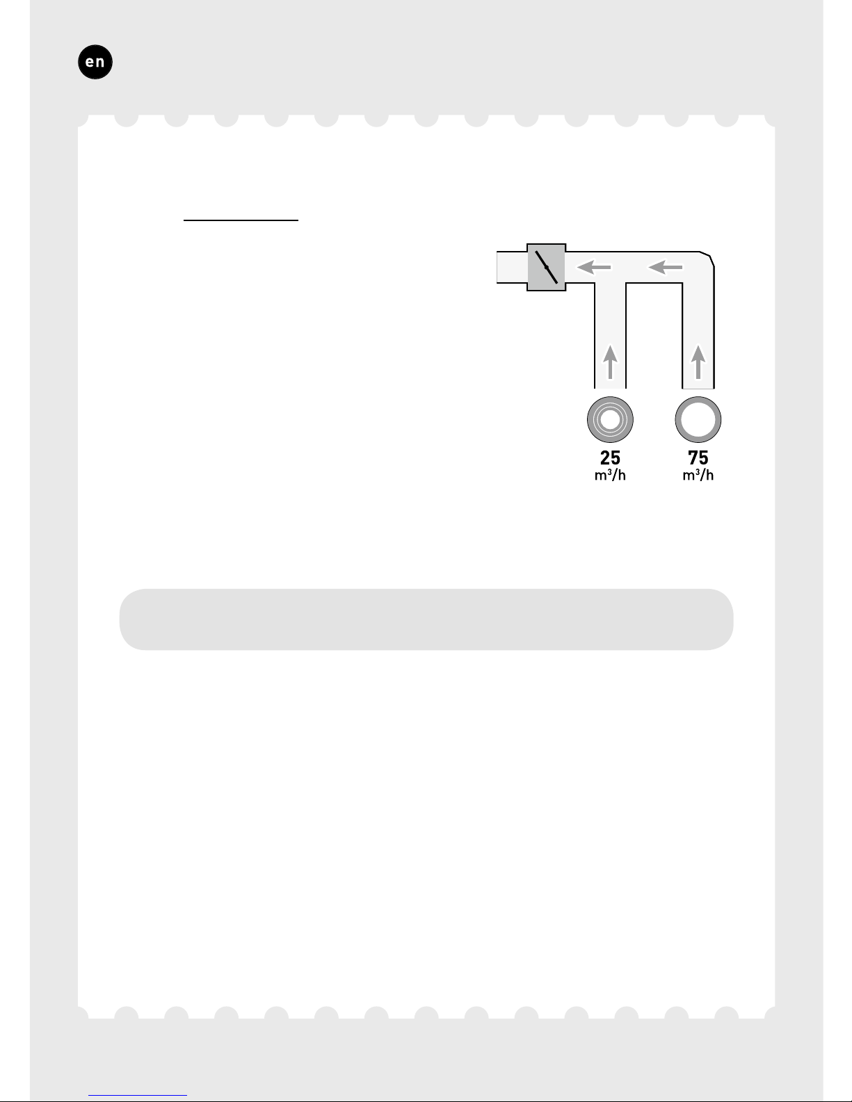
SITUATION 3: Multiple exhaust vents per zone
with different flow rates
Set the exhaust vents so they
match the desired flow rate in
line with the table on page 100.
7B.
Configuration
The configuration procedure covers the use of multiple (stand-alone)
iAV Control valves.
Important, before setting up: Close all windows and doors, and avoid
air leaks in the ventilation ducts. Set all window ventilators to the 100%
open position. Any Tronicwindow ventilators will open automatically.
For quick and easy configuration, it is recommended that a constant
volume control be provided in each zone (flow rate = sum of underlying
flow rates).
Page 31
103
ENGLISH
PWM
2
3
4
4
9
5a5b
6
7
8b8b
1
75 m³/h50 m³/h25 m³/h
75 m³/h50 m³/h25 m³/h
150 m³/h
150 m³/h
Zone 2
Zone 1
Constant volume control
Page 32

104
ENGLISH
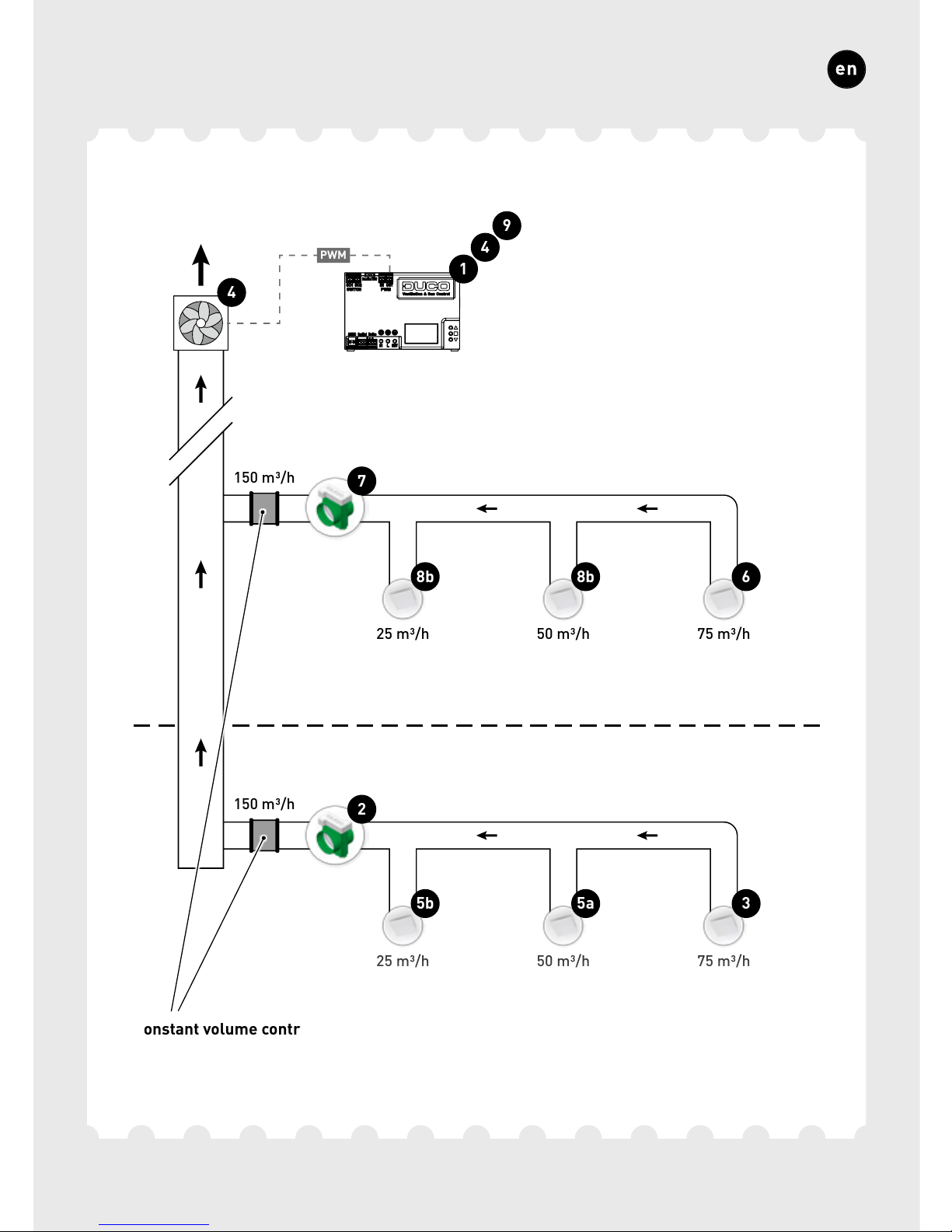
The steps set out below match the numbers shown in the preceding
illustration.
1
Press ‘HIGH’ or ‘LOW’ on the IQ-unit to activate the configuration
mode for 30 minutes.
2
With zonally controlled exhaust only: select the zone with the
highest pressure drop (usually the zone located furthest from the
central extract unit).
3
Measure the exhaust vent with the highest pressure drop (usually
the vent with the highest flow rate).
4
Adjust the fan speed of the central extract unit until the desired
flow rate through the exhaust vent in step
3
has been attained.
This can be done using the arrow keys on the IQ-unit if it has
been connected to it (via PWM or WTW). If the zone is fitted with
a constant volume control, the point must be found at which the
fan runs as slow as possible while attaining the desired flow rate.
If the fan speed cannot be adjusted, the desired flow rate can be
attained by fine-tuning the feed-through component (e.g. using the
arrow keys on the iAV control valve)
2
. Note that this can gener-
ate more noise and higher energy consumption!
5
Measure any remaining vents within the current zone and fine-
tune them using the exhaust vent. Work from highest to lowest
flow rate.
Page 33

105
ENGLISH
Now complete the remaining zones. To do this, repeat the following
steps, working towards the central extract unit.
6
Select the exhaust vent with the highest flow rate.
7
Adjust the flow rate through the exhaust vent in step
6
by
fine-tuning the feed-through component (e.g. using the arrow keys
on the iAV control valve).
8
Measure any remaining vents within the current zone and fine-
tune them using the exhaust vent. Work from highest to lowest
flow rate.
9
Exit configuration mode by pressing ‘HIGH’ on the iAV Control valve
or on the IQ-unit.
Page 34
106
ENGLISH
Most factory settings for the network and components will be sufficient
as they are, nonetheless depending on the situation a few parameters
will need to be set correctly. This can be done via the Display menu on
the IQ-unit or using the Duco Network Tool.
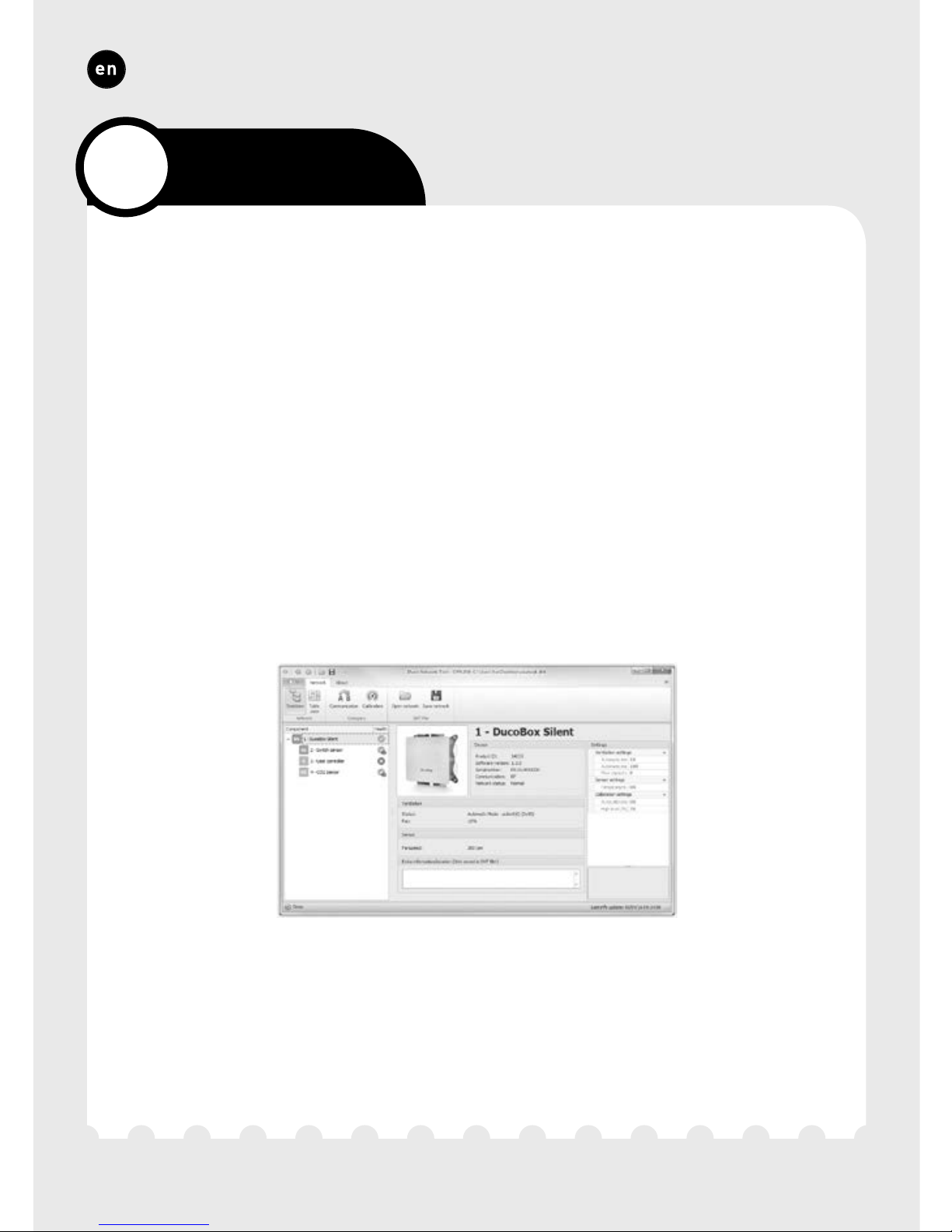
Duco Network Tool*
This user-friendly software is the ideal way of changing settings
and pinpointing problems in the system. The Duco Network Tool is
issued to every installer after attending a free training course at the
Duco Academy. Please refer to our website or your Duco dealer for
further information.
* Only in Belgium and the Netherlands
Duco Network Tool
8
Settings
Page 35
107
ENGLISH
DISPLAY
MENU
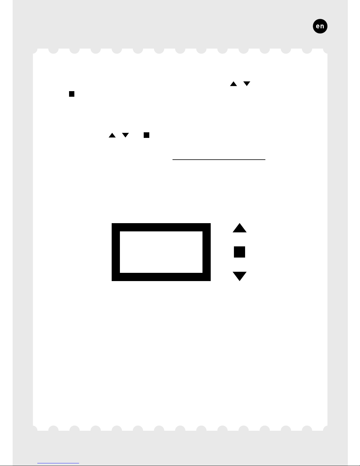
Display menu
The menu can be operated using the arrow keys ( , ) and the enter
key ( ). Use the arrow keys to scroll through the menu. Use ‘>BACK’
at the end of each menu to return to the menu above. Press the arrow
keys together briefly to return to the main menu.
The display will switch off automatically after 2 minutes of inactivity.
Press a button ( , or ) to reactivate the display.
Please refer to information sheet Display menu (L8000015)
at www.duco.eu for a complete overview of the display menu.
Page 36
108
ENGLISH
8A.
Setting the time
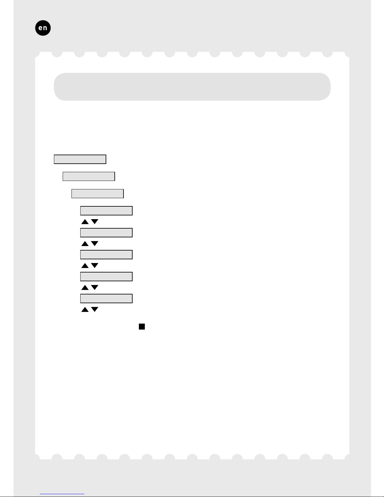
The time needs to be set on the IQ-unit for functions including NightBoost to work correctly. Navigate to the parameters listed below and
set them correctly:
>Cong
>Box
>Time
>Time
20:05
>Day
22
>Month
March
>Year
2015
>Timezon
+1HRS
Confirm using Enter (
) in each case.
Page 37
109
ENGLISH
8B.
NightBoost
Duco’s NightBoost function is used to set the ventilation system during
the summer to assist in cooling down high indoor temperatures.
This fully automatic smart (night) cooling function temporarily deactivates demand control at indoor temperatures of 24 °C and over, and
causes the system to operate at nominal value. Not only does this
reduce the risk of overheating, it also reduces the need for cooling.
Smart NightBoost algorithms ensure energy-efficient operation without disturbing night rest.
When using ‘Tronic’ window ventilators, outdoor temperature is also
measured for even greater operating efficiency in the NightBoost
function.
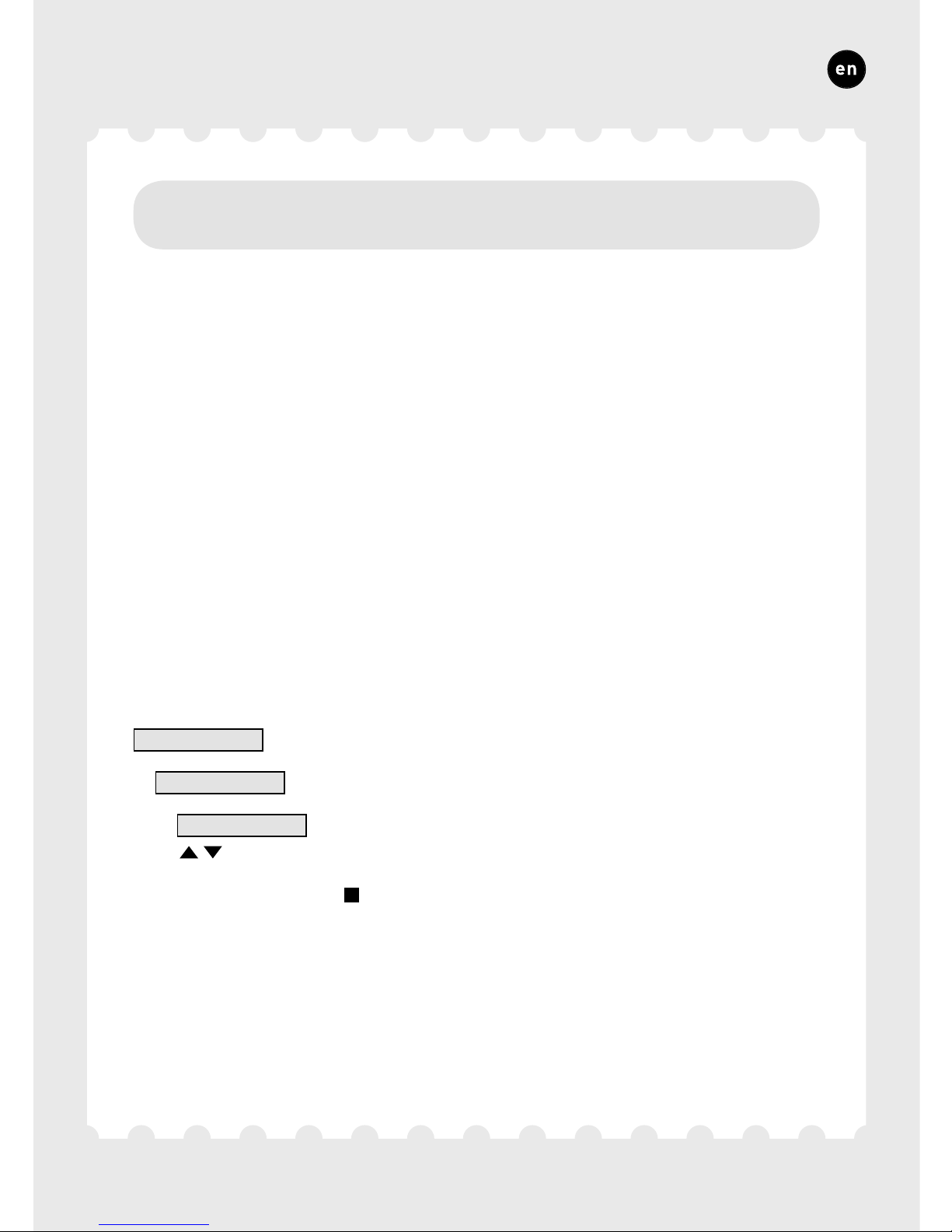
NightBoost is not activated as standard in the IQ-unit. Ensure the time
of day has been set (see section8A) and complete the following steps
to activate NightBoost:
>Cong
>NghtBst
>Mode
ON
Confirm using Enter (
).
Page 38

110
ENGLISH
8C.
ModBus
A ModBus link can be used to read out and alter ventilation system
parameters from connected equipment (e.g. a building management
system). Please refer to information sheet ModBus (L8000009) at
www.duco.eu for comprehensive information about ModBus.
Page 39

111
Page 40

Geïnstalleerd door:
Installé par:
Installed by:
 Loading...