

Duco DucoBox Silent Series, DucoBox Silent 400, DucoBox Silent 325, DucoBox Silent 225 Quick Start Manual
DucoBox Silent
Productversie / version du produit / product version: H2S3
Quick Start
NEDERLANDS
FRANÇAIS
ENGLISH
L0001779-F 19.12.2016
NEDERLANDS
FRANÇAIS
ENGLISH
Inhoudstafel
1 Inleiding ................................................ 3
2
Aansluitingen & knoppen ................ 4
3
Bekabeling ........................................... 5
4
Plaatsing ............................................... 6
Positie
.................................................6
Aansluiting luchtkanalen
Bevestiging
5
Extra sturingsmogelijkheden ........ 7
........................................6
3-standenschakelaar* via
Perilex
.................................................7
Boxsensor
6
Elektronische installatie ................. 8
..........................................7
Instellingen wijzigen
Installer / User mode
Instelling type woning
Componenten aanmelden
Componenten verwijderen /
vervangen
7
Inregeling luchthoeveelheid ........ 12
....................................... 11
Afvoerventielen instellen
Inregelen
Controle
8
Productkaart .....................................15
......................................... 13
........................................... 15
.............6
......................8
....................8
...................9
......... 10
........... 12
Table des matières
1 Introduction ......................................... 3
2
Connecteurs et boutons .................. 4
3
Câblage ................................................. 5
4
Mise en place ...................................... 6
Position
Raccordements des conduits
d’air
Fixation
5
Option de contrôle
supplémentaires
Interrupteur à 3 positions* via
Perilex
Sonde box
6
Installation electronique ................. 8
Modifier les réglages
Installer / User mode
Réglage du type d’habitation
Ajouter des composants
Éliminer / remplacer des
composants
7
Réglage d’air .....................................12
Réglage des bouches
d’extraction
Réglage
Contrôle
8
Fiche de produit ...............................15
...............................................6
......................................................6
...............................................6
................................ 7
.................................................7
..........................................7
.....................8
....................8
......9
............ 10
.................................... 11
.................................... 12
............................................ 13
........................................... 15
Table of contents
1 Introduction ......................................... 3
2
Connector & buttons ........................ 4
3
Wiring .................................................... 5
4
Fitting .................................................... 6
Position
Air duct connections
Fixing
5
Additional control options ............... 7
3-position switch* via Perilex
Box Sensor
6
Electronical installation .................. 8
Change settings
Installer / User mode
Setting type of home
Pairing components
Removing / replacing
components
7
Air calibration ...................................12
Setting exhaust vents
Calibration
Checking
8
Product sheet ....................................15
...............................................6
......................6
...................................................6
.....7
........................................7
...............................8
....................8
......................9
.................... 10
................................... 11
................. 12
...................................... 13
......................................... 15
Voor informatie wat betreft garantie, onderhoud, technische gegevens, enzovoort, zie www.duco.eu.
Installatie, aansluiting, onderhoud en herstellingen dienen door een erkend installateur te gebeuren.
De elektronische onderdelen van dit product kunnen onder spanning staan. Vermijd contact met
water.
Informations sur la garantie, l’entretien, la fiche technique, etc. sur www.duco.eu.
L’installation, le raccordement, l’entretien et les réparations doivent être effectués par un installateur
agréé. Les éléments électroniques de ce produit peuvent être sous tension. Éviter tout contact avec
l’eau.
See www.duco.eu for information regarding warranty, maintenance, technical data, etc.
Installation, connection, maintenance and repairs are to be carried out by an accredited installer. The
electronic components of this product may be live. Avoid contact with water.
DUCO, HANDELSSTRAAT 19
VEURNE, B8630
09
Handelsstraat 19 - 8630 Veurne - Belgium - tel +32 58 33 00 33 - fax +32 58 33 00 44 - info@duco.eu - www.duco.eu
CO2
HIGH
LOW
INST
RH
1
Inleiding
Introduction
Introduction
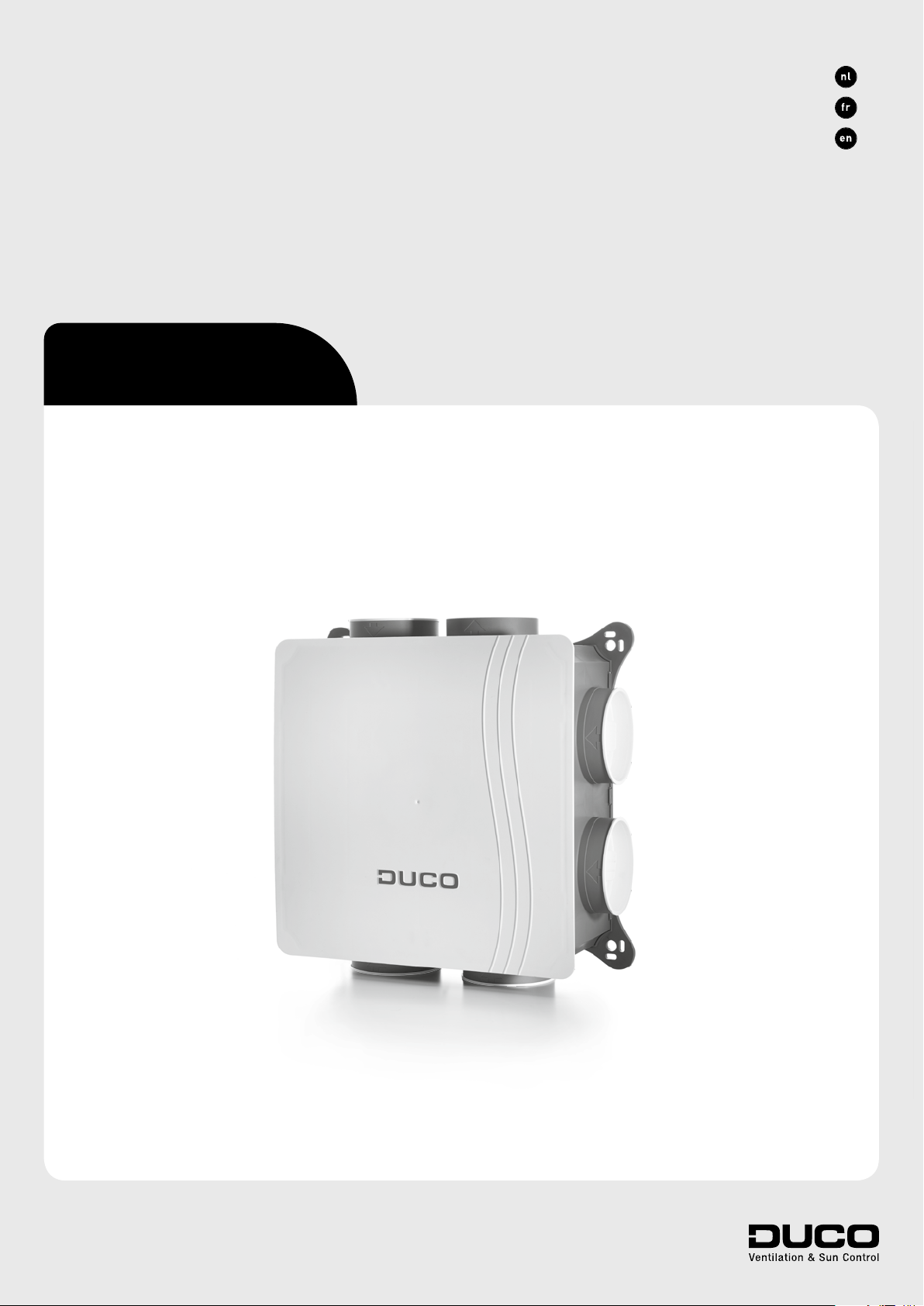
Van harte gefeliciteerd met uw
DucoBox Silent, de stilste box van Europa! De DucoBox Silent vervult twee
functies binnen een Duco Vraaggestuurd Natuurlijk Ventilatiesysteem:
Enerzijds is het de afzuigventilator
die vervuilde lucht, met te hoge CO
2
of
vochtigheidsgehaltes, afvoert.
Anderzijds is het de ‘master’, oftewel het brein van het systeem. Deze
ontvangt en interpreteert signalen van
de slave componenten (metingen via
sensor of manuele input) en stuurt op
basis hiervan het ventilatiesysteem
aan.
Félicitations pour votre
DucoBox Silent, le box le plus silencieux de l’Europe! Le DucoBox Silent
remplit deux fonctions dans un
Système de ventilation Naturelle à la
Demande Duco:
D’une part, il agit comme un venti-
lateur d’extraction qui évacue l’air
pollué par des niveaux de CO
ou
2
d’humidité trop élevés.
D’autre part, c’est le «maître», soit
le cerveau du système. Il reçoit et
interprète les signaux provenant des
composants «esclaves» (mesures
via le capteur ou saisie manuelle) et
commande le système de ventilation
sur cette base.
Congratulations on your
DucoBox Silent, the quietest box in
Europe! The DucoBox Silent performs two functions in a Duco Demand-Controlled Natural Ventilation
System:
On the one hand, it is the extractor
fan that exhausts contaminated air
with excessive CO
content or humi-
2
dity.
On the other hand, it is the system
master or brain which receives and
interprets signals from slave components (measurements from sensors or manual input), on the basis
of which it controls the ventilation
system.
Master
Slave
3
2
CO2
HIGH
LOW
INST
RH
CO2
HIGH
LOW
INST
RH
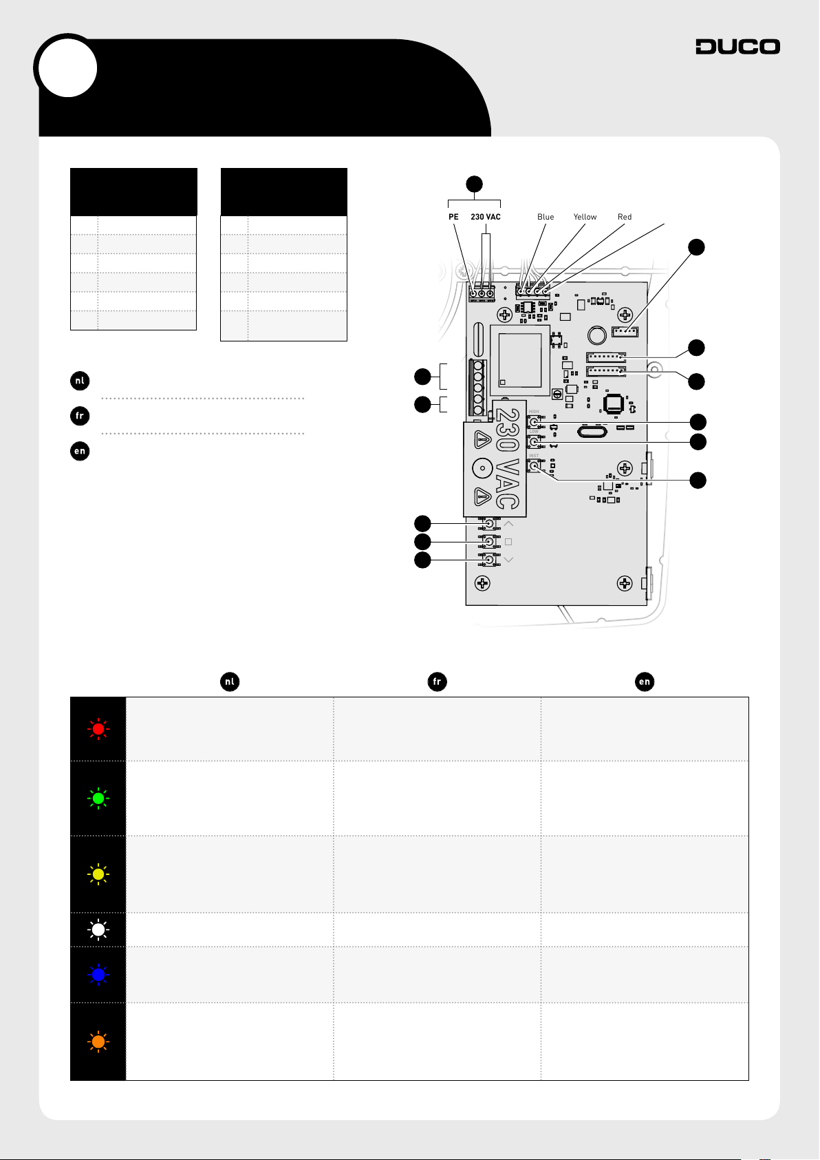
Aansluitingen & knoppen
Connecteurs et boutons
Connector & buttons
AANSLUITINGEN
CONNECTEURS
CONNECTORS
1 Power 230 VAC
2 Perilex
3 Boxsensor RH
4 Boxsensor CO
2
5 Duco Network Tool
6 Fan
De afbeelding en de aansluitingen kunnen variëren
afhankelijk van de uitvoering van het product.
L’illustration et les raccordements peuvent varier en
fonction de l’exécution du produit.
Illustrations and connections may vary depending on
product configuration.
A UP
B ENTER
C DOWN
D HIGH
E LOW
F INST
KNOPPEN
BOUTONS
BUTTONS
(installer mode)
1
2
A
B
C
6
PE 230 VAC
L
1
N
PE
L
2
L
3
Blauw
Bleu
Blue
Geel
Jaune
Yellow
Rood
Rouge
Red
Wit
Blanc
White
5
3
4
D
E
F
LEDINDICATIE
INDICATION LED
LED INDICATION
ROOD (traag knipperen)
ROOD (snel knipperen)
Bezig met aanmelden
GROEN (traag knipperen)
GROEN (snel knipperen)
In netwerk, wachtend op
geassocieerde componenten
GEEL (traag knipperen)
Overgangsfase (a.u.b. wachten)
(inregeling van het systeem bezig)
Visualisatie van component
wanneer er wijzigingen doorgevoerd
worden via de master
Het systeem werkt niet correct omdat
de DucoBox niet gecalibreerd is. Start
de box opnieuw op. Volg de richtlijnen
in ‘10 niet te missen tips’ indien het
probleem zich blijft voordoen.
Niet in netwerk
In netwerk
GEEL (aan)
Initialisatie
WIT of UIT
Normaal
BLAUW
ORANJE
ROUGE (clignotement lent)
Pas en réseau
ROUGE (clignotement rapide)
Connexion en cours
VERT (clignotement lent)
En réseau
VERT (clignotement rapide)
En réseau et en attente de
composants associés
JAUNE (clignotement lent)
Phase de transition (attendre s.v.p.)
JAUNE (allumé)
Initialisation
(réglage du système en cours)
BLANC ou VIDE
Normal
BLEU
Visualisation du composant lorsque des
modifications sont apportées via le maître
ORANGE
Le système ne fonctionne pas correctement
parce que le DucoBox n’est pas étalonné.
Redémarrez le DucoBox. Suivez les
directives des “10 conseils à ne pas
manquer” si le problème persiste.
RED (blinking slowly)
Not in network
RED (blinking rapidly)
Logging in
GREEN (blinking slowly)
In network
GREEN (blinking rapidly)
In network, waiting for
associated components
YELLOW (clignotement rapide)
Transitional phase (please wait
YELLOW (on)
Initialising
(system configuration in progress)
WHITE or OFF
Normal
BLUE
Component is displayed if changes are
being put through via the master.
ORANGE
The system is not working correctly because
the DucoBox has not been calibrated. Restart
the box. Follow the guidelines in ‘10 essential
tips’ if the problem recurs continually.
4
3
Bekabeling
Câblage
Wiring
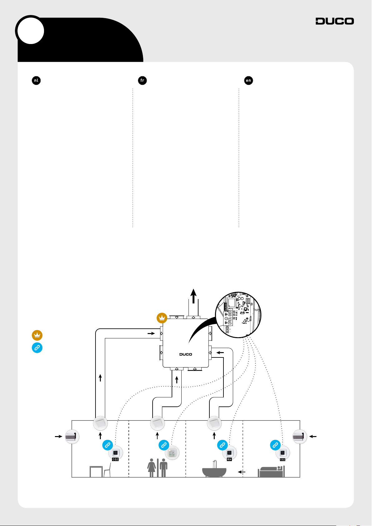
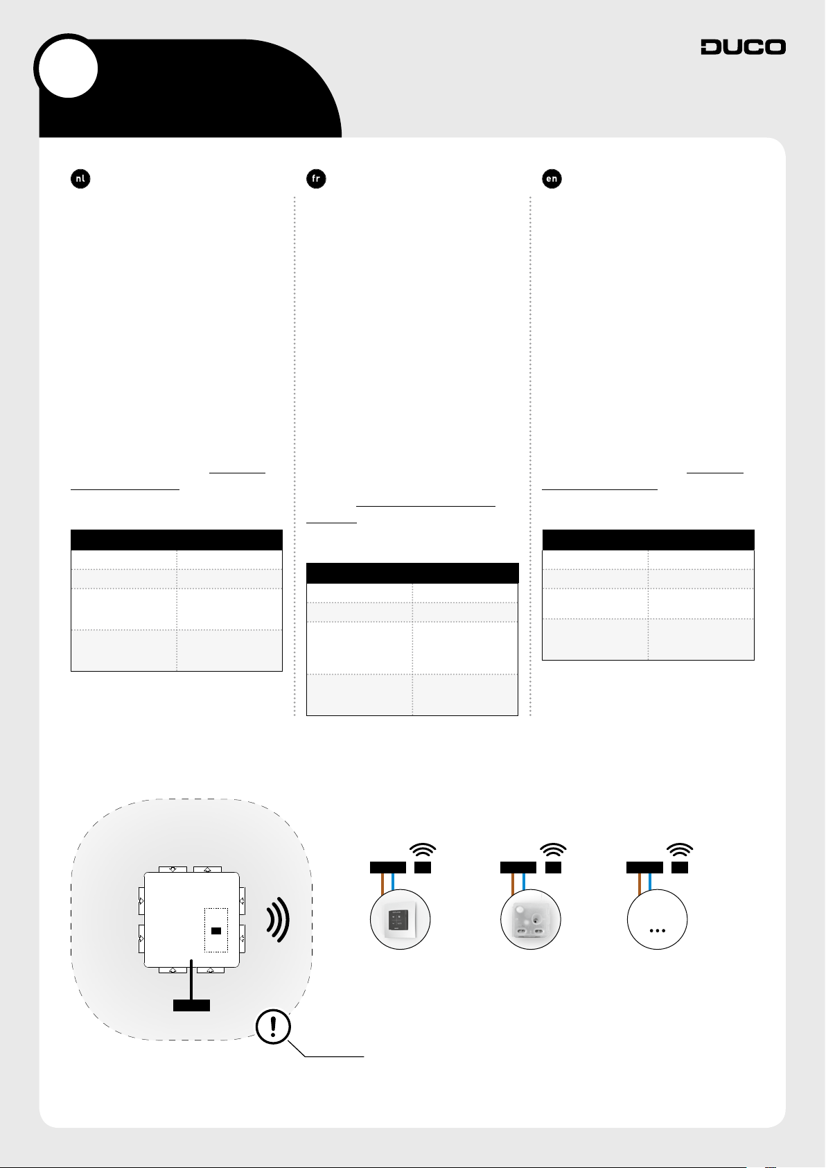
De DucoBox Silent communiceert met
‘slave’ componenten via een draadloze
(RF) verbinding. RF-componenten
hebben een maximaal bereik van
350 meter in vrij veld. In een gebouw
zal deze afstand door obstakels veel
kleiner zijn. Houd daarom rekening
met objecten zoals muren, beton en
metaal. Alle ‘slave’ componenten (uitgezonderd de batterijgevoede) doen
ook dienst als repeater. Signalen van
componenten die geen (sterke) verbinding met het ‘master’ component
kunnen maken, worden automatisch
via maximaal één ander component
(=hoppunt) doorgestuurd. Raadpleeg het informatieblad L8000001
“RFcommunicatie” op www.duco.eu
voor meer info.
DUCO RF
Voeding 230 VAC
Frequentie 868 Mhz
Maximum afstand
Maximum
componenten
350 m in vrij veld
(kleiner door
obstakels)
Tot 25 draadloze
componenten in
één systeem
Le DucoBox Silent communique avec
des composants «esclaves» via une
connexion sans fil (RF). Les composants RF ont une portée maximale de
350mètres en champ libre. Dans un
bâtiment, cette distance sera fortement réduite en raison de la présence
d’obstacles. Tenez donc compte des
objets tels que murs, béton et métal.
Tous les composants «esclaves» (à
l’exception de ceux qui sont alimentés
par piles) font également office de répéteurs. Les signaux de composants
qui ne peuvent pas établir de liaison
(forte) avec le composant ‘maître’ sont
automatiquement retransmis par un
autre composant maximum (= point
de saut). Reportez-vous à la fiche de
données L8000001 «Communica-
tionRF» sur www.duco.eu pour un
complément d’informations.
DUCO RF
Alimentation 230 VCA
Fréquence 868 Mhz
jusqu’à 350 m
Distance maximale
Composants
maximum
en champ libre
(réduite en présence
d’obstacles)
Jusqu’à 25
composants sans fil
dans un système
The DucoBox Silent communicates
with slave components through a
wireless (RF) connection. RF components have a maximum free-field
range of 350 metres. This distance will
be much less in a building because
of obstacles so you will need to allow
for features such as walls, concrete
and metal. All slave components
(except those which are battery powered) also act as repeaters. Signals
from components that are unable to
make a (strong) connection with the
master component are forwarded
automatically via no more than one
other component (= hop point). Please
refer to information sheet L8000001
“RFcommunication” at www.duco.eu
for further information.
DUCO RF
Power supply 230 VAC
Frequency 868 Mhz
Maximum distance
Maximum number
of components
350 m, free field (less
through obstacles)
Up to 25 wireless
components in a
single system
DucoBox
Silent
230 VAC
RF230 VAC RF230 VAC
RF
Bedieningsschakelaar
Commutateur de commande
User controller
RF-obstakelvrije zone (minstens 30 cm)
RF - zone sans obstacle (au moins 30 cm)
RF obstacle-free zone (at least 30 cm)
Schakelcontact
Contact de commutation
Switch sensor
Max 25 RF componenten
Max 25 composants RF
Max 25 RF components
RF230 VAC
5
 Loading...