

Duco DucoBox Focus Series, DucoBox Focus 400, DucoBox Focus 325, DucoBox Focus 225 Quick Start Manual
DucoBox Focus
Quick Start
NEDERLANDS
FRANÇAIS
ENGLISH
L0001778VA 18.05.2016
NEDERLANDS
FRANÇAIS
ENGLISH
Inhoudstafel
1 Inleiding ................................................ 3
2
Aansluitingen & knoppen ................ 4
3
Bekabeling ........................................... 5
Bekabelingsschema
RF (draadloze communicatie)
Wired (bekabelde
communicatie)
4
Plaatsing ............................................... 7
Positie
.................................................7
Aansluiting luchtkanalen
Bevestiging
5
Regelkleppen ...................................... 8
6
Installatie ............................................. 9
........................................7
Installer / User mode
Componenten installeren
Andere acties
7
Inregeling ...........................................13
Afvoerventielen instellen
Inregelen
Controle
8
Instellingen ........................................16
......................................... 15
........................................... 15
Debiet regelklep aanpassen
Tijd instellen
NightBoost
ModBus
9
Productkaart .....................................19
...................................... 18
............................................ 18
.......................5
.....6
.................................6
.............7
....................9
.......... 10
................................. 12
........... 13
..... 17
.................................. 17
Table des matières
1 Introduction ......................................... 3
2
Connecteurs et boutons .................. 4
3
Câblage ................................................. 5
Schéma de connexion
RF (communication sans fil)
Câblé (communication par
câbles)
.................................................6
4
Mise en place ...................................... 7
Position
...............................................7
Raccordements des conduits
d’air
......................................................7
Fixation
5
Clapets de réglage ............................ 8
6
Installation ........................................... 9
...............................................7
Installer / User mode
Installer composants
Autres actions
7
Réglage d’air .....................................13
Réglage des bouches
d’extraction
Réglage
Contrôle
8
Réglages .............................................16
.................................... 13
............................................ 15
........................................... 15
Ajustement du clapet de
réglage
............................................. 17
Réglage de l’heure
NightBoost
ModBus
9
Fiche de produit ...............................19
...................................... 18
............................................ 18
....................5
.......6
....................9
.................. 10
............................... 12
....................... 17
Table of contents
1 Introduction ......................................... 3
2
Connector & buttons ........................ 4
3
Wiring .................................................... 5
Cabling diagram
RF (wireless communication)
Wired (cabled communication)
4
Fitting .................................................... 7
Position
...............................................7
Air duct connections
Fixing
...................................................7
5
Control valves ..................................... 8
6
Installation ........................................... 9
Installer / User mode
Install components
Other operations
7
Air calibration ...................................13
Setting exhaust vents
Calibration
Checking
8
Settings ...............................................16
Adjusting control valve flow
rate
.................................................... 17
Setting the time
NightBoost
ModBus
9
Product sheet ....................................19
............................................ 18
..............................5
.....6
...6
......................7
....................9
...................... 10
.......................... 12
................. 13
...................................... 15
......................................... 15
............................ 17
...................................... 18
Voor informatie wat betreft garantie, onderhoud, technische gegevens, enzovoort, zie www.duco.eu.
Installatie, aansluiting, onderhoud en herstellingen dienen door een erkend installateur te gebeuren.
De elektronische onderdelen van dit product kunnen onder spanning staan. Vermijd contact met
water.
Informations sur la garantie, l’entretien, la fiche technique, etc. sur www.duco.eu.
L’installation, le raccordement, l’entretien et les réparations doivent être effectués par un installateur
agréé. Les éléments électroniques de ce produit peuvent être sous tension. Éviter tout contact avec
l’eau.
See www.duco.eu for information regarding warranty, maintenance, technical data, etc.
Installation, connection, maintenance and repairs are to be carried out by an accredited installer. The
electronic components of this product may be live. Avoid contact with water.
DUCO, HANDELSSTRAAT 19
VEURNE, B8630
09
Handelsstraat 19 - 8630 Veurne - Belgium - tel +32 58 33 00 33 - fax +32 58 33 00 44 - info@duco.eu - www.duco.eu
1
Inleiding
Introduction
Introduction
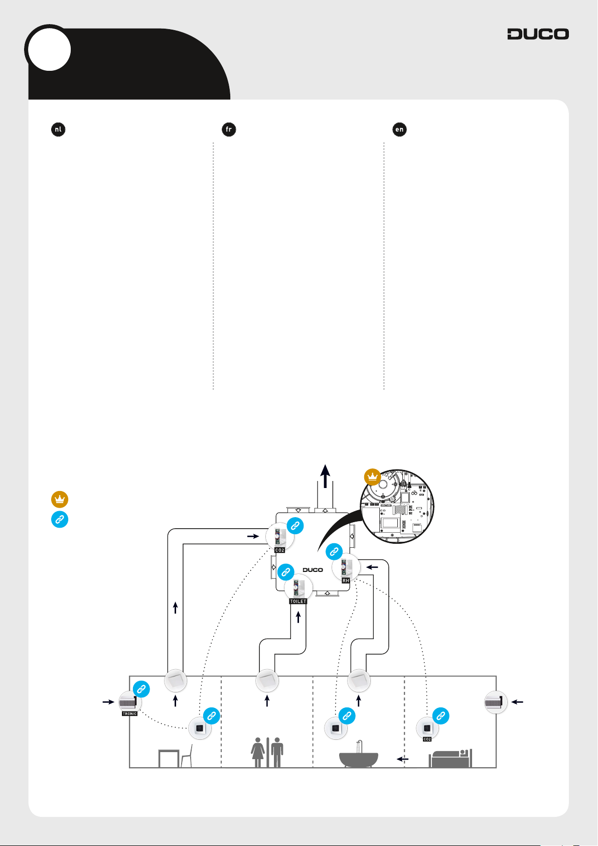
Van harte gefeliciteerd met uw
DucoBox Focus, de slimste box van
Europa! De DucoBox Focus vervult
twee functies binnen een Duco Vraaggestuurd Natuurlijk Ventilatiesysteem:
Enerzijds is het de afzuigventilator
die vervuilde lucht, met te hoge CO
vochtigheidsgehaltes, afvoert. Dankzij
geïntegreerde regelkleppen wordt
enkel lucht afgevoerd in de zone waar
dit nodig is.
Anderzijds is het de ‘master’, oftewel het brein van het systeem. Deze
ontvangt en interpreteert signalen van
de ‘slave’ componenten (metingen via
sensor of manuele input) en stuurt op
basis hiervan het ventilatiesysteem
aan.
2
of
Félicitations pour votre
DucoBox Focus, le box le plus intelligent de l’Europe! Le DucoBox Focus
remplit deux fonctions dans un
Système de ventilation Naturelle à la
Demande Duco:
D’une part, il agit comme un venti-
lateur d’extraction qui évacue l’air
pollué par des niveaux de CO
midité trop élevés. Grâce aux clapets
de réglage intégrés, l’air n’est évacué
dans la zone où c’est nécessaire.
D’autre part, c’est le «maître», soit
le cerveau du système. Il reçoit et
interprète les signaux provenant des
composants «esclaves» (mesures
via le capteur ou saisie manuelle) et
commande le système de ventilation
sur cette base.
ou d’hu-
2
Congratulations on your
DucoBox Focus, the smartest box in
Europe! The DucoBox Focus performs two functions in a Duco Demand-Controlled Natural Ventilation
System:
On the one hand it is the extractor fan
that exhausts contaminated air with
excessive CO
Thanks to integrated control valves,
air is only exhausted in the zone that
requires it.
On the other hand it is the system
master or brain which receives and
interprets signals from slave components (measurements from sensors or manual input), on the basis
of which it controls the ventilation
system.
content or humidity.
2
Master
Slave
3
2
Aansluitingen & knoppen
Connecteurs et boutons
Connector & buttons
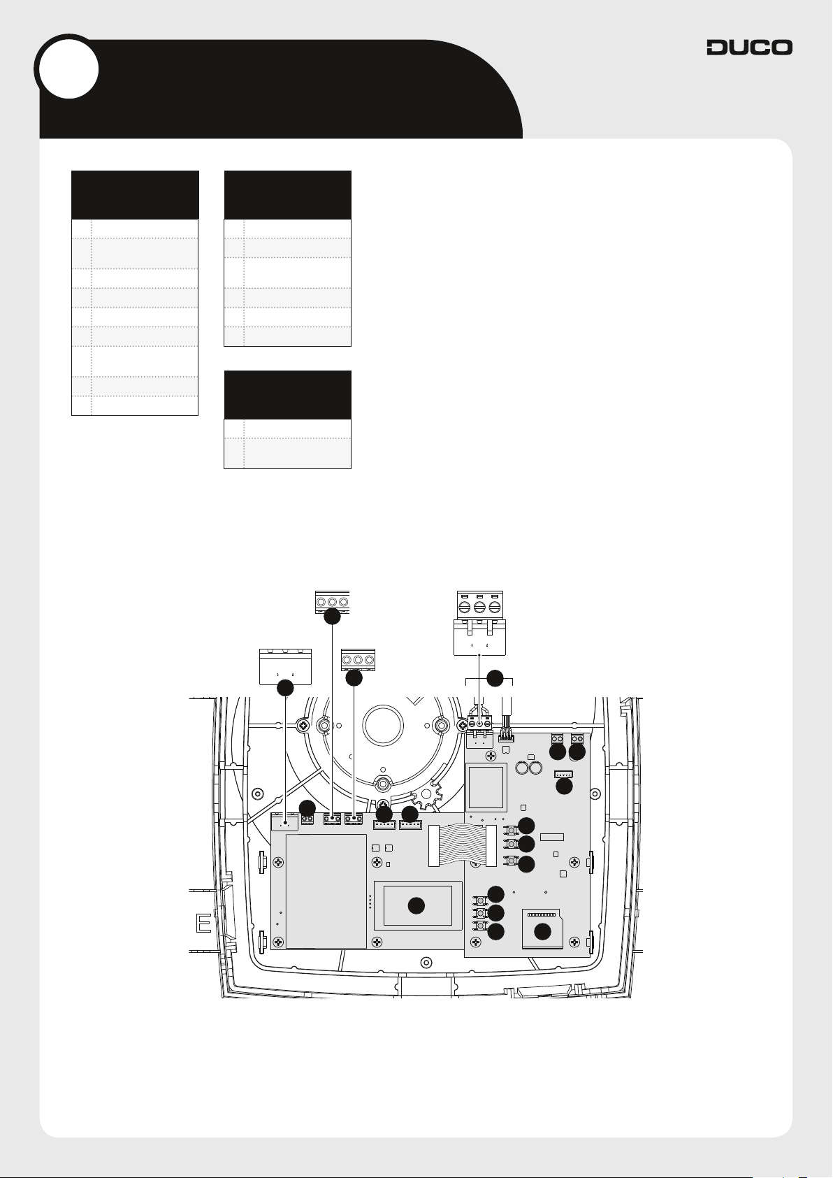
AANSLUITINGEN
CONNECTEURS
CONNECTORS
1 Power 230 VAC
Switch contact 2 -
2
onboard (n133)
3 ModBus (A/-,B/+,GND)
4 Duco Wired (A,B,GND)
5 Connection Valve
6 Fan
Switch contact 1 -
7
onboard (n132)
8 PWM IN
9 Duco Network Tool
KNOPPEN
BOUTONS
BUTTONS
A HIGH
B LOW
C
D UP
E ENTER
F DOWN
INST
(installer mode)
DIVERSEN
DIVERS
MISCELLANEOUS
10 Display
11
SD card
(software update)
+ -
GNDLBNA
PE L N
3
PE
1
GND B A
4
2
5 5
10
6
7 8
9
A
B
C
D
E
F
11
4
3
Bekabeling
Câblage
Wiring
De DucoBox Focus kan zowel via een
draadloze (RF) of bedrade (Wired)
verbinding communiceren met ‘slave’
componenten. Beide communicatietypes kunnen gecombineerd worden in
één systeem.
Daarnaast zijn aansluitingen via een
schakelcontact (2 stuks) en ModBus
mogelijk.
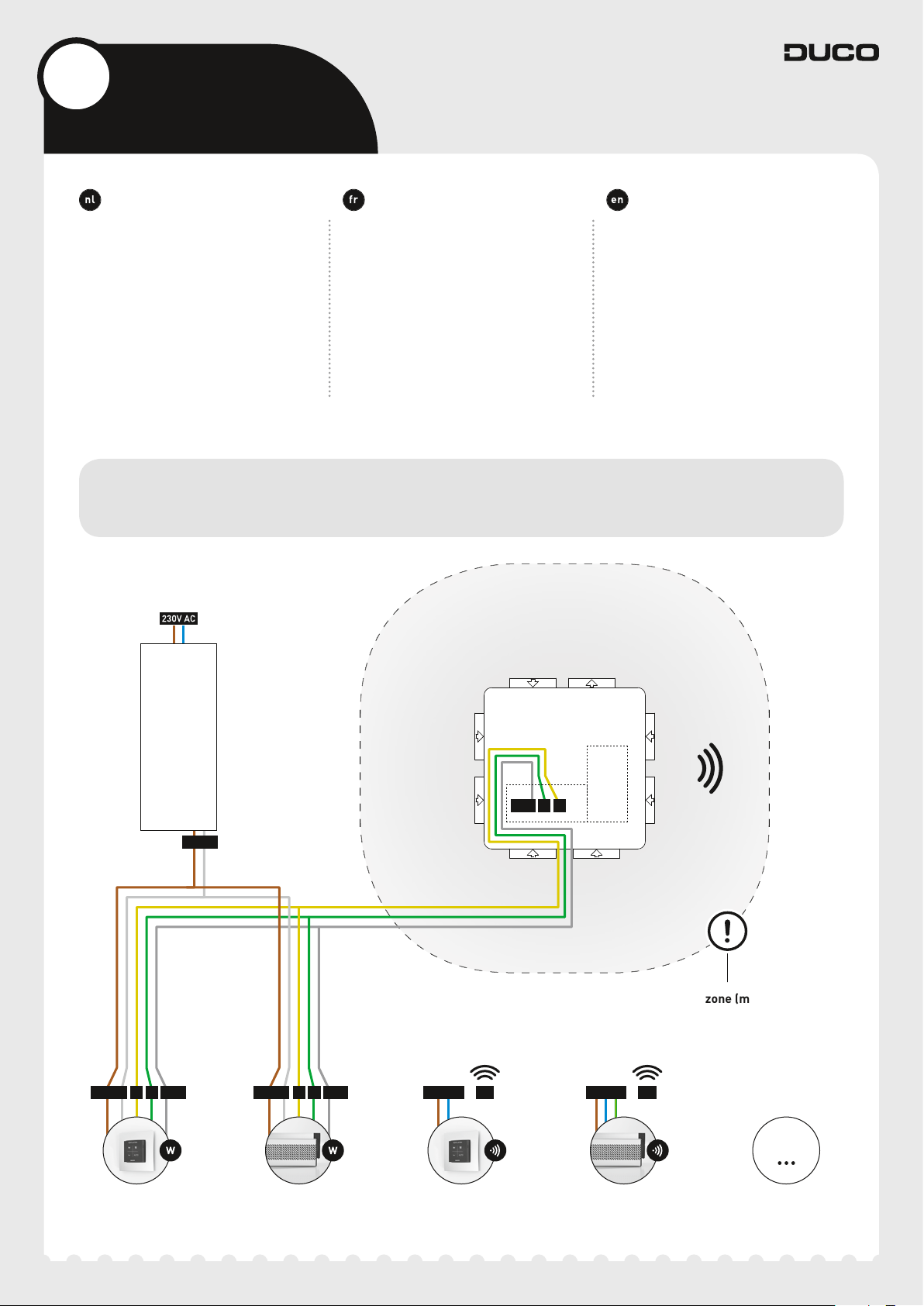
Bekabelingsschema
3A.
Schéma de connexion
Cabling diagram
Le DucoBox Focus peut communiquer
via une connexion sans fil (RF) ou
câblée (Wired) avec les composants
esclaves. Ces deux types de communication peuvent être combinés dans
un seul système.
En outre, les raccordement via un
Contact de commutation (2 pièces) et
ModBus sont possibles.
The DucoBox Focus is able to communicate with slave components via a
wireless (RF) or wired link. Both types
of communication can be combined in
one system.
In addition, connections can also be
made via a Switch sensor (quantity
of2) and ModBus.
POWER
SUPPLY
24 VDC
Wired
24 VDC 24 VDC
B B
GND GND
DucoBox
Focus
GND
B
A
RF-obstakelvrije zone (minstens 30 cm)
RF - zone sans obstacle (au moins 30 cm)
RF obstacle-free zone (at least 30 cm)
230 VAC 230 VACA A
RF RF
RF
Bedieningsschakelaar
Commutateur de commande
User controller
Tronic rooster
Tronic grille
Tronic vent
Bedieningsschakelaar
Commutateur de commande
User controller
Tronic rooster
Tronic grille
Tronic vent
Max 99 Wired
+ 25 RF
5

3B.
RF (draadloze communicatie)
RF (communication sans fil)
RF (wireless communication)
RF-componenten ( ) hebben een
maximaal bereik van 350 meter in vrij
veld. In een gebouw zal deze afstand
door obstakels veel kleiner zijn. Houd
daarom rekening met objecten zoals
muren, beton en metaal. Alle ‘slave’ componenten (uitgezonderd de
batterijgevoede) doen ook dienst als
repeater. Signalen van componenten
die geen (sterke) verbinding met het
‘master’ component kunnen maken,
worden automatisch via maximaal één
ander, niet-batterijgevoed component
(=hoppunt) doorgestuurd. Raadpleeg
het informatieblad L8000001 “RF
communicatie” op www.duco.eu voor
meer info.
DUCO RF
Voeding 230 VAC
Frequentie 868 Mhz
Maximum afstand
Maximum
componenten
350 m in vrij veld
(kleiner door
obstakels)
Tot 25 draadloze
componenten in
één systeem
Les composants RF ( ) ont une
portée maximale de 350mètres en
champ libre. Dans un bâtiment, cette
distance sera fortement réduite en
raison de la présence d’obstacles.
Tenez donc compte des objets tels que
murs, béton et métal. Tous les composants ‘esclaves’ (à l’exception de
ceux qui sont alimentés par piles) font
également office de répéteurs. Les signaux de composants qui ne peuvent
pas établir de liaison (forte) avec le
composant ‘maître’ sont automatiquement retransmis par un autre composant maximum non alimenté par pile
(= point de saut). Reportez-vous à la
fiche de données L8000001 «Communication RF» sur www.duco.eu pour
un complément d’informations.
DUCO RF
Alimentation 230 VCA
Fréquence 868 Mhz
jusqu’à 350 m
Distance maximale
Composants
maximum
en champ libre
(réduite en présence
d’obstacles)
Jusqu’à 25
composants sans fil
dans un système
RF components ( ) have a maxi-
mum free-field range of 350 metres.
This distance will be much less in a
building because of obstacles so you
will need to allow for features such as
walls, concrete and metal. All slave
components (except those which are
battery powered) also act as repeaters. Signals from components that
are unable to make a (strong) connection with the master component are
forwarded automatically via no more
than one other non-battery-powered
component (= hop point). Please refer
to information sheet L8000001 “RF
communication” at www.duco.eu for
further information.
DUCO RF
Power supply 230 VAC
Frequency 868 Mhz
Maximum distance
Maximum number
of components
350 m, free field (less
through obstacles)
Up to 25 wireless
components in a
single system
Wired (bekabelde communicatie)
3C.
Wired componenten ( ) kunnen
doorgelust worden. Hierdoor is een
aparte kabel per component niet
vereist. Het is mogelijk om met één
centrale voeding te werken.
Voeding 24 VDC
Bekabeling
Maximum afstand tot 300 m
Maximum
componenten
6
Câblé (communication par câbles)
Wired (cabled communication)
Les composants câblés ( ) peuvent
être mis en boucle. Il n’est donc pas
nécessaire de prévoir un câble séparé
par composant. Il est possible de travailler avec une alimentation centrale.
DUCO WIRED
Alimentation 24 VCC
3 aders communicatie
(A, B, GND)
Tot 99 bedrade
componenten in
één systeem
Câblage
Distance maximale jusqu’à 300 m
Composants
maximum
DUCO WIRED
3 conducteurs pour
la communication
composants câblés
dans un système
(A, B, GND)
Jusqu’à 99
Wired components ( ) can be
daisy-chained. This means that a
separate cable will not be required
for each component. A single central
power supply can be used.
DUCO WIRED
Power supply 24 VDC
Cabling
Maximum distance up to 300 m
Maximum number
of components
3-core communication
(A, B, GND)
Up to 99 wired
components in a
single system
 Loading...