

Page 1
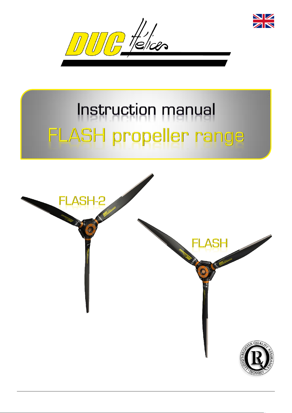
Chemin de la Madone - 69210 LENTILLY - FRANCE
Phone: + 33 (0)4 74 72 12 69 - Fax: +33 (0)4 74 72 10 01
E-mail: [email protected] - www.duc-helices.com
ISO 9001:2008 Certified Company
for its Quality System Management
DH_FSH_BE_01_F Made in France 09/10/2013
Page 2

This instruction manual is to be maintained throughout the life of the propeller.
He may have to evolve. The owner must check with the DUC Hélices company
the latest version being valid applicable to the propeller.
Page 3
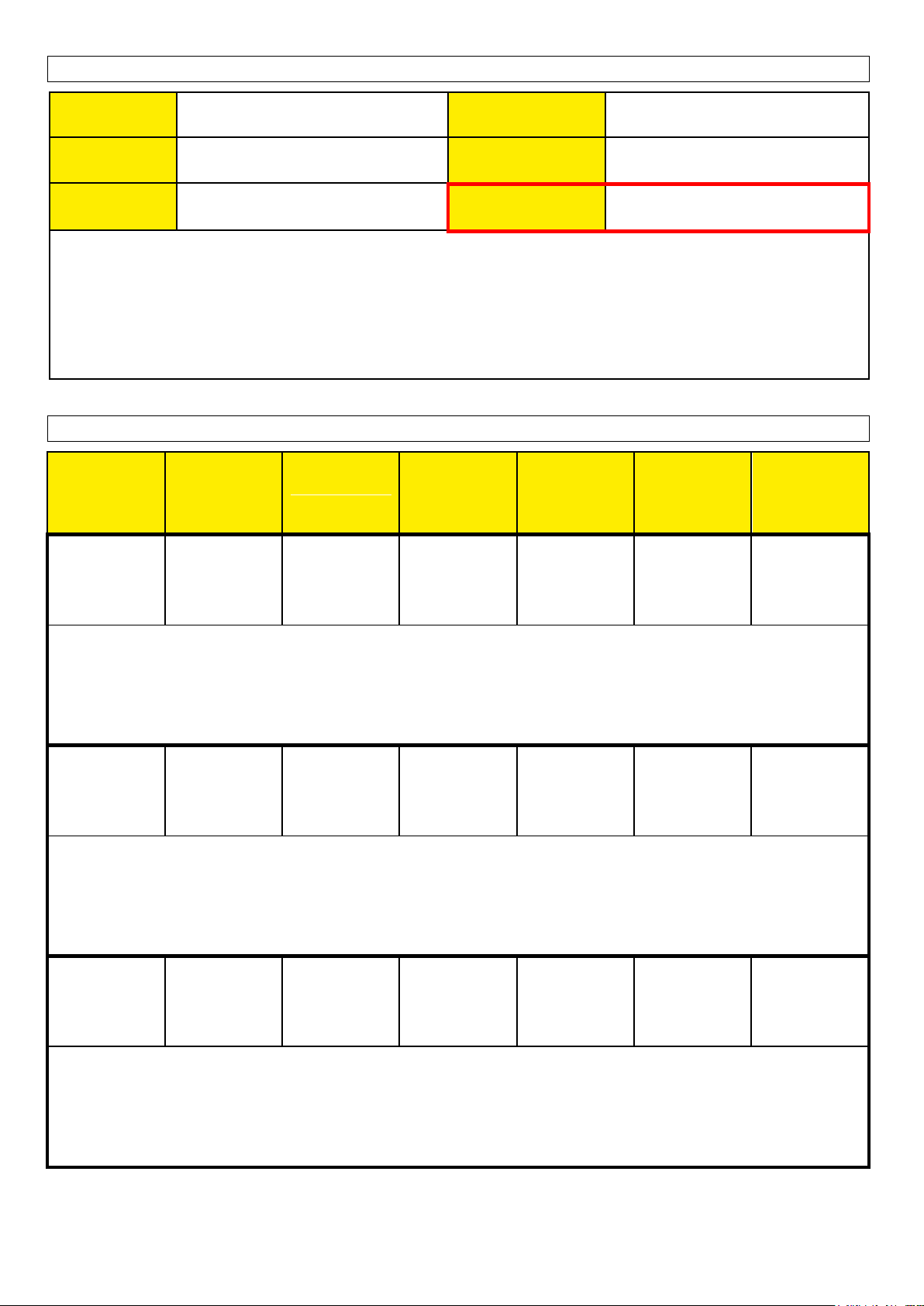
Identification
Date
Delivery note n°
Owner
Engine/Gearbox
ratio
Aircraft
1st recommended
pitch blade angle
Notes: ..............................................................................................................................................................................
..........................................................................................................................................................................................
..........................................................................................................................................................................................
..........................................................................................................................................................................................
..........................................................................................................................................................................................
Performances
PITCH (°) at
25cm from the
tip of the
blade
TAKE-OFF
DISTANCE
(m)
CLIMB RATE
(ft/min or m/s)
SLOW
CRUISE
(km/h & rpm)
VARIOUS
CRUISE
(km/h & rpm)
FAST
CRUISE
(km/h & rpm)
FULL
THROTTLE
VARIO 0
(km/h & rpm)
Notes (Date, Number of people, Weight, Weather, …): ...............................................................................................
...........................................................................................................................................................................................
...........................................................................................................................................................................................
...........................................................................................................................................................................................
Notes (Date, Number of people, Weight, Weather, …): ...............................................................................................
...........................................................................................................................................................................................
...........................................................................................................................................................................................
...........................................................................................................................................................................................
Notes (Date, Number of people, Weight, Weather, …): ...............................................................................................
...........................................................................................................................................................................................
...........................................................................................................................................................................................
...........................................................................................................................................................................................
Page 4

Summary
1. Presentation of the FLASH propeller ......................................................................................................................... 5
1.1. Description ........................................................................................................................................................ 5
1.2. Characteristics ................................................................................................................................................... 5
1.1. Shielding leading edge in Inconel ..................................................................................................................... 6
1.2. Accessories ...................................................................................................................................................... 6
1.1. Sales reference ................................................................................................................................................. 6
2. Applications ................................................................................................................................................................ 7
3. Installation precautions .............................................................................................................................................. 7
4. Components of the FLASH propeller ......................................................................................................................... 8
4.1. Mounting configuration of the FLASH propeller ................................................................................................ 8
4.2. Mounting screws ............................................................................................................................................... 8
4.3. Exploded view for propeller ............................................................................................................................... 9
4.4. List of required tools .......................................................................................................................................... 9
5. Assembly instruction of the propeller ....................................................................................................................... 10
5.1. Assembly of the propeller ................................................................................................................................ 10
5.2. Installation on the aircraft ................................................................................................................................ 11
5.3. Setting of the propeller & Finalization of the installation ................................................................................. 14
6. Precautions .............................................................................................................................................................. 17
7. Indications for testing ............................................................................................................................................... 17
8. Installation without spinner or with spinner other than DUC .................................................................................... 18
9. Potential use & Propeller maintenance.................................................................................................................... 18
9.1. Potential use of the propeller: Unlimited ......................................................................................................... 18
9.2. Propeller maintenance schedule ..................................................................................................................... 18
9.1. Regular maintenance (by the user) ................................................................................................................. 19
9.2. General maintenance (by the user or an aeronautics workshop) ................................................................... 19
9.3. Complete maintenance (by DUC Hélices) ...................................................................................................... 20
10. General terms of sale............................................................................................................................................... 20
10.1. Ordering procedure ......................................................................................................................................... 20
10.2. Delivery ........................................................................................................................................................... 20
10.3. Price ................................................................................................................................................................ 20
10.4. Right of withdrawal .......................................................................................................................................... 20
10.5. Warranties ....................................................................................................................................................... 20
10.6. Privacy Policy .................................................................................................................................................. 20
10.7. Litigation .......................................................................................................................................................... 20
11. Annexes ................................................................................................................................................................... 21
11.1. Dimension of the engine propeller-shaft ......................................................................................................... 21
11.2. Airfoil ............................................................................................................................................................... 22
11.3. Moment of inertia of the FLASH propeller ....................................................................................................... 22
11.4. Operating limitation of the FLASH propeller ................................................................................................... 22
11.5. Identification marking of the propeller ............................................................................................................. 23
11.6. Calculation of the centrifugal force of the FLASH Inconel blade .................................................................... 24
11.7. Centrifugal force test under EASA CS-P350 specification ............................................................................. 24
11.8. Breaking test of the two-blade Inconel FLASH propeller ................................................................................ 25
11.9. Declaration of conformance of the FLASH propeller ...................................................................................... 27
4/28
Page 5
1. Presentation of the FLASH propeller
rpm
efficiency ƞ
1.1. Description
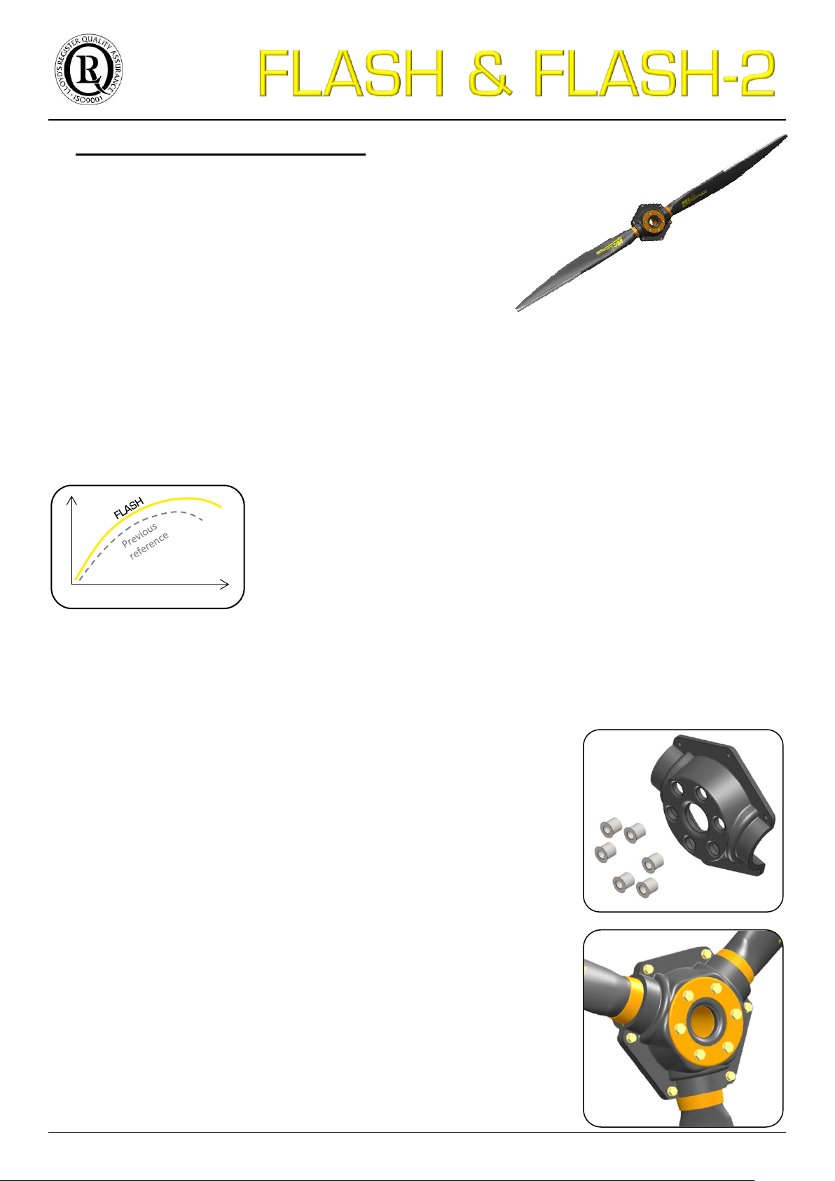
The FLASH propeller range is has a new innovative design, specific
about its twisting axis and center of pressure.
Its aerodynamic design allows a "constant speed" effect, limiting
variations in engine speed between on ground and in flight.
These propellers allow for high efficiency throughout the flight envelope i.e.:
Improved takeoff and climb rate due to higher engine speed, then higher engine efficiency
Many cruise extension
A high user comfort
The blades and the hub of the FLASH propeller range are manufactured according the DUC Hélices company
technologies, from unidirectional layers of carbon fibers prepreg epoxy resin.
Their composite structures are defined to obtain the maximum stresses in torsion
and bending. Therefore "constant speed" effect is not related to deformation of the
blade but its geometry and specific profile.
Due to its specific geometric definition, excellent performance is obtained in
both aerodynamic and acoustic, but also in consumption.
1.2. Characteristics
The FLASH propeller range is available:
Tractor or pusher configuration (available in right & left rotation)
Diameters Ø1520, Ø1620, Ø1660, Ø1730, Ø1850mm and others tailor made
Ø59.8 Ø63.8 Ø65.4 Ø68.1 Ø72.8"
Two-blade & Three-blade – FLASH 3.35 & 4.40 kg (7.39 & 9.70 lb.)
FLASH-2 3.45 & 4.53 kg (7. 61 & 9.99 lb.)
Shielded leading edge in Inconel®
Carbon composite hub with metallic inserts
Direct assembly on the propeller-shaft Ø101.6mm
Excellence version “FLASH-R”:
Longitudinal reinforced carbon structure
Higher bending strength
Titanium color finishing
Advanced controls
5/28
Page 6
Designation
Reference
Part number
Two-blade Inconel FLASH propeller, Right
01-19-001
H-FSH_2-D-I
Two-blade Inconel FLASH propeller, Left
01-19-002
H-FSH_2-G-I
Two-blade Inconel FLASH-R propeller, Right
01-20-001
H-FSH_2-D-R_I
Two-blade Inconel FLASH-R propeller, Left
01-20-002
H-FSH_2-G-R_I
Three-blade Inconel FLASH propeller, Right
01-21-001
H-FSH_3-D-I
Three-blade Inconel FLASH propeller, Left
01-21-002
H-FSH_3-G-I
Three-blade Inconel FLASH-R propeller, Right
01-22-001
H-FSH_3-D-R_I
Three-blade Inconel FLASH-R propeller, Left
01-22-002
H-FSH_3-G-R_I
Three-blade Inconel FLASH-2 propeller, Left
01-23-002
H-FSH2_3-G-I
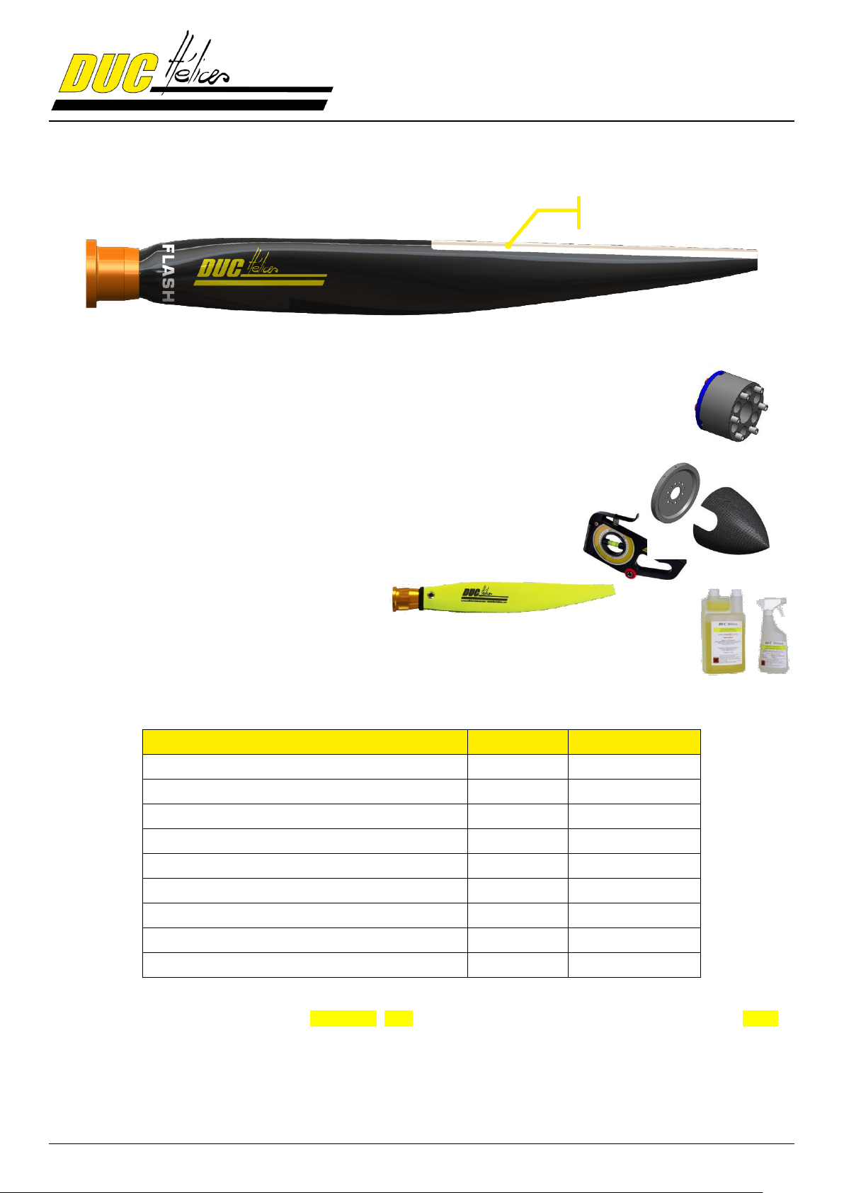
Inconel shielding
1.1. Shielding leading edge in Inconel
The leading edge of the FLASH blades is equipped with a metallic shielding in Inconel®. This material is refractory
stainless with a very high hardness of surface.
1.2. Accessories
Aluminum mounting spacer (Direct mounting on P.C.D Ø101.6mm/Ø4”)
Moves the plane of the propeller to adjust the position according the engine hood
Aluminum adaptor spacer (Other mounting as SAE1, SAE2, …)
Move the propeller plane and adaptor the P.C.D fixation of the propeller
Spinner available in diameter Ø250mm (Ø9.8") & Ø340mm (Ø14.4”)
Adjusting tool for the setting of the pitch angle of the blades
Neoprene cover protection of the blade
Cleaning treatment for composite propellers
Save money! A clean propeller is more efficient and decreases the fuel consumption.
1.1. Sales reference
Note:
Specify the flight regulation aircraft (E.g.: Ultra-light, LSA…) and diameter when ordering (E.g.: ref. 01-21-001/1730).
For more information about the propeller marking, see section 11.5.
6/28
Page 7
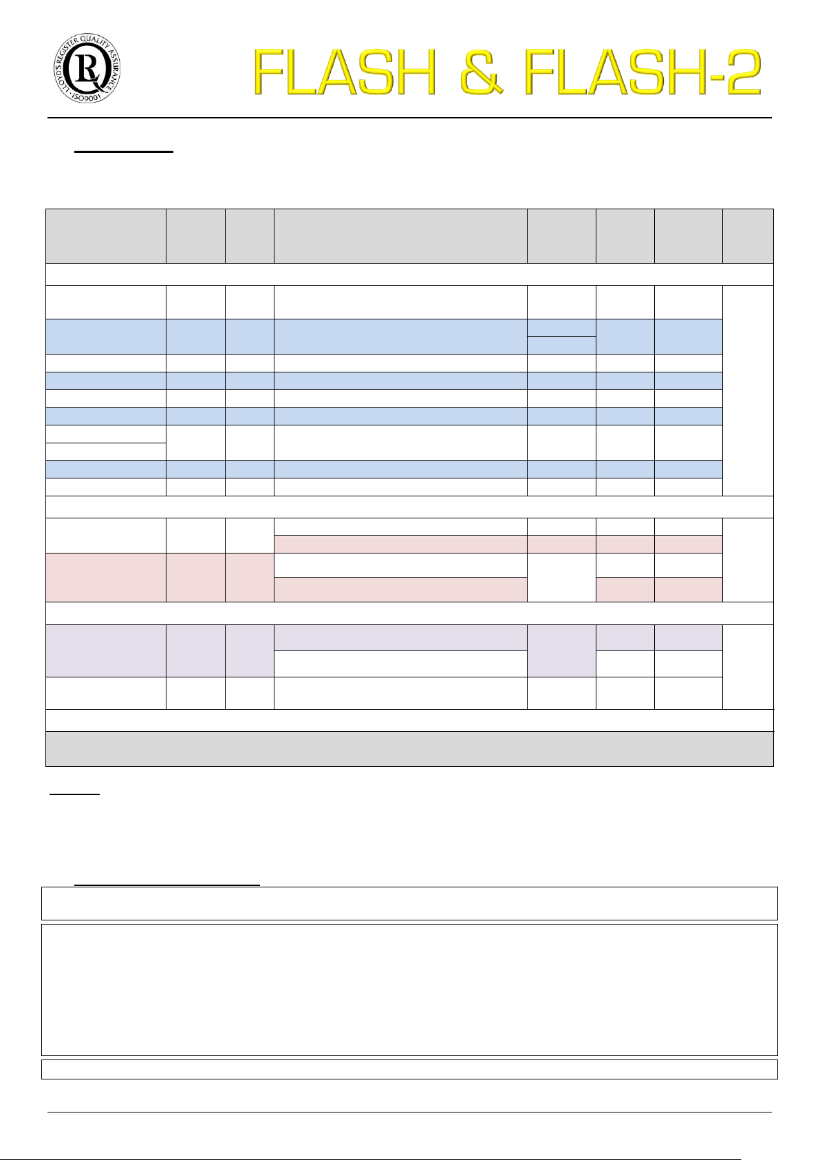
2. Applications
Engine
Type
Gear
box
Recommended propeller
Propeller
diameter
(inch)
Blade
angle
(°)
Blade
angle
allowed
range(°)
TBO
(hour)
3 AXIS – TRACTOR
ROTAX 912
4 strokes
2.273
2.43
Two-blade Inconel FLASH, Tractor Right
Ø1730
22°
20° → 28°
2000
ROTAX
912S/912iS/914
4 strokes
2.43
Three-blade Inconel FLASH, Tractor Right
Ø1730
24°
22° → 32°
Ø1750
JABIRU 2200
4 strokes
-
Two-blade Inconel FLASH, Tractor Right
Ø1520
18°
15° → 23°
JABIRU 3300
4 strokes
-
Two-blade Inconel FLASH, Tractor Right
Ø1620
19°
16° → 24°
UL Power 260i
4 strokes
-
Two-blade Inconel FLASH, Tractor Right
Ø1520
18°
15° → 23°
UL Power 350iS
4 strokes
-
Two-blade Inconel FLASH, Tractor Right
Ø1620
20°
17° → 25°
Continental O-200
4 strokes
-
Three-blade Inconel FLASH, Tractor Right
Ø1660
19°
17° → 25°
Lycoming O-235
Lycoming O-320
4 strokes
-
Three-blade Inconel FLASH-R, Tractor Right
Ø1850
20°
18° → 26°
Lycoming O-360
4 strokes
-
Three-blade Inconel FLASH-R, Tractor Right
Ø1900
20°
18° → 26°
3 AXIS – PUSHER
ROTAX 912
4 strokes
2.273
2.43
Three-blade Inconel FLASH, Pusher Left
Ø1730
22°
20° → 28°
2000
Three-blade Inconel FLASH-2, Pusher Left
Ø1730
21°
19° → 27°
ROTAX
912S/912iS/914
4 strokes
2.43
Three-blade Inconel FLASH, Pusher Left
Ø1700
Ø1730
Ø1750
22°
20° → 28°
Three-blade Inconel FLASH-2, Pusher Left
21°
19° → 29°
AUTOGYRO & TRIKES
ROTAX
912S/912iS/914
4 strokes
2.43
Three-blade Inconel FLASH, Pusher Left
Ø1700
Ø1730
Ø1750
22°
20° → 28°
2000
Three-blade Inconel FLASH-2, Pusher Left
21°
19° → 29°
BMW R12000 GF
de SECOP
4 strokes
2.7
Three-blade Inconel FLASH, Pusher Right
Ø1750
22°
20° → 28°
OTHER APPLICATIONS
For all other applications, thank you to contact the DUC Hélices company to study the possibility of adapting the
FLASH propeller.
The DUC propellers have an unlimited flight potential in normal operation. To keep the unlimited potential,
DUC Hélices defined a TBO (Time Between Overhaul) for a propeller depending on its engine.
Refer to section 9. Potential use & Propeller maintenance for more information.
* Ø1850mm = 72.83"; Ø1730mm = Ø68.12»; Ø1660mm = Ø65.4»; Ø1620mm = Ø63.8»; Ø1520mm = Ø59.8"
Remark
The values of the pitch angle are theoretical and associated with the engine. This setting should be adjusted
according to the aircraft (see section 7. Indications for testing).
For proper use of the propeller, refer to section 9. Potential use & Propeller maintenance.
3. Installation precautions
WARNING Make sure the ignition is turned off before starting any type of operation on the propeller.
Do not run the engine without propeller, engine damage will result.
IMPORTANT The blades of a propeller are part of a whole. DO NOT INTERCHANGE with other similar blades from
propeller. The propeller blades are manufactured to their application. Their structure, weight and balance are different
from a propeller to another.
The spinner is an important element for cooling the engine. The aircraft must not fly without a spinner.
Fitting a different spinner will be an addendum to this manual approved by the DUC to confirm its compatibility with the mounting of
the propeller.
The propeller is delivered with the appropriate screws. The change of the screws is contrary to our recommendations unless
validated by the manufacturers.
WARRANTY CONDITIONS The user is still flying under its full responsibility (see 10. General terms of sale).
7/28
Page 8
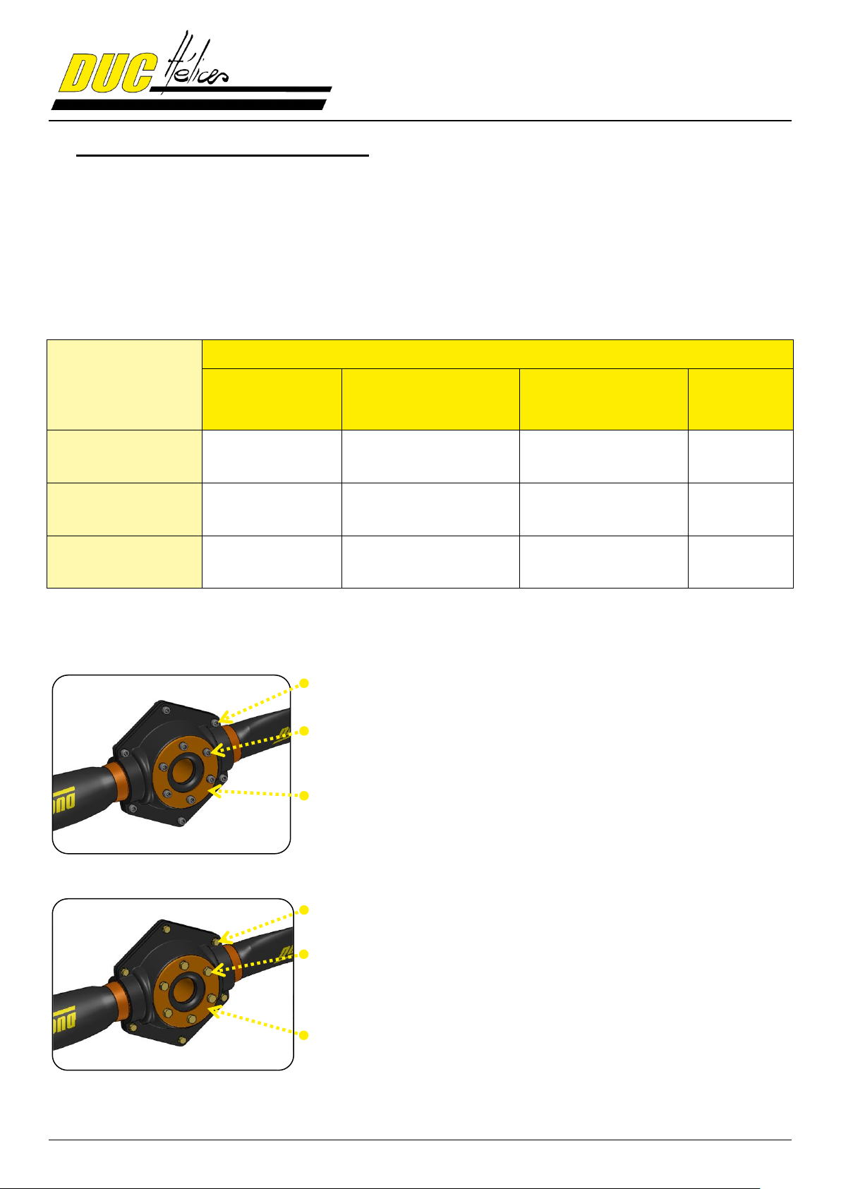
MOUNTING
ENGINE PROPELLER-SHAFT
Ø4" / Ø101.6mm
(Ex: Rotax, Jabiru)
Type SAE 1
Ø4-3/8" / Ø111.125mm
(Ex: Continental O-200)
Type SAE2
Ø4-3/4" / Ø120.65mm
(Ex: Lycoming O-360)
Other
≠ Ø101.6mm
direct on propeller-
shaft (without spacer)
X
with spacer
X
with adaptor spacer
X X
X
Hub assembly:
Screws CHC M8, Nylstop locking nuts & pin contact washers
Propeller fixation:
Screws CHC M8
(Screw length adapted according the mounting direct or with spacer)
Hub clamping washer:
Aluminum with holes Ø8mm on P.C.D. Ø101.6mm
Hub assembly:
Screws AN5, locking nuts & standard washers
Propeller fixation:
SAE1: Screws AN6 (3/8")
SAE2: Screws AN8 (1/2")
(Screw length adapted according the length of the spacer)
Hub clamping washer: Aluminum
SAE1: Holes for screws AN6 (3/8") on P.C.D. Ø4-3/8" (Ø111.125mm)
SAE2: Holes for screws AN8 (1/2") on P.C.D. Ø4-3/4" (Ø120.65mm)
4. Components of the FLASH propeller
The FLASH & FLASH-2 propellers are available in several versions and can be mounted on different model of engine.
4.1. Mounting configuration of the FLASH propeller
Here is a configuration table of the FLASH propeller mounting according the propeller-shaft of the engine.
If needed, see annex 11.1. Dimension of the engine propeller-shaft.
4.2. Mounting screws
Rotax/Jabiru mounting 4.2.1.
SAE1/SAE2 mounting 4.2.2.
8/28
Page 9
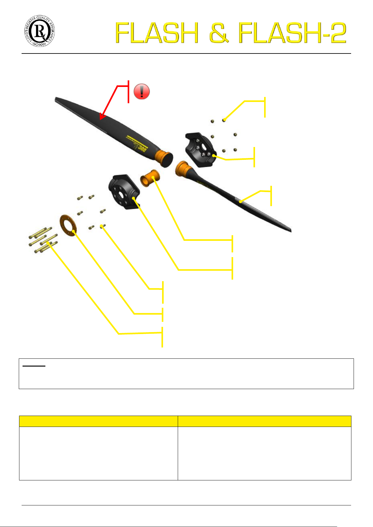
4.3. Exploded view for propeller
Rotax/Jabiru mounting
SAE1/SAE2 mounting
M8 Torque Hex key (Tightening range: 22 to 30 Nm)
M8 Torque Wrench (Tightening range: 22 to 30 Nm)
Inclinometer (pitch adjusting tool)
Plastic mallet
Torque Screwdriver (Tightening: 4 Nm)
M8 Torque Hex key (Tightening range: 22 to 30 Nm)
M8 Torque Wrench (Tightening range: 22 to 30 Nm)
3/8 or 1/2 Torque Wrench (Tightening range: 30 to 45 Nm)
Inclinometer (pitch adjusting tool)
Plastic mallet
Torque Screwdriver (Tightening: 4 Nm)
FLASH blade
(x2 or x3)
Screws & washers
for hub assembly (x6)
Hub camping washer (x1)
Locking nuts & washers
for hub assembly (x6)
Rear half-hub (x1)
with rear metallic inserts (x6)
Fixing screws and washers of the propeller
adapted according the mounting (x6)
Internal hub spacer (x1)
Caution when handling the blades
CUTTING TRAILING EDGE
Front half-hub (x1)
with front metallic inserts (x6)
Remark
This exploded view shows the principle of the FLASH propeller assembly. The size of all of these components
changes depending on the configuration of the propeller (diameter hole of the metallic inserts of the half-hub, length of
the screws…).
4.4. List of required tools
9/28
Page 10
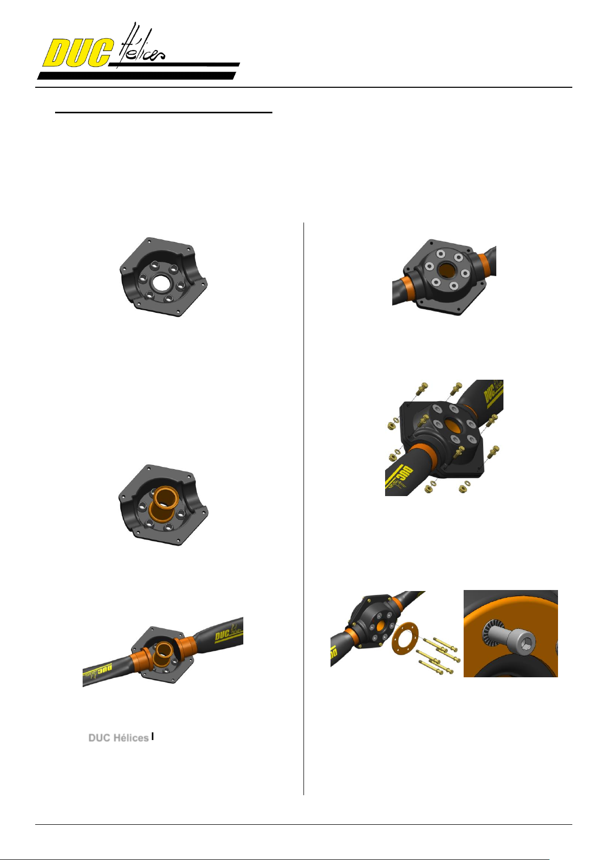
5. Assembly instruction of the propeller
The assembly of the FLASH propellers is shown below. It is recommended to assemble the propeller on a worktable
before installing it on the plane. The procedure is the same for two-blade and three-blade FLASH propellers.
For further information, contact the DUC Hélices Company.
5.1. Assembly of the propeller
STEP 1.
Place the rear half-hub on a worktable.
Be careful not to invert with the front hub half.
Depending on your installation, the rear half-hub is one
mounted on the propeller-shaft of the engine or on a
spacer. The holes of the metal inserts of the rear halfhub are higher than the holes of the metal inserts of the
front half-hub.
STEP 2.
Place the hub spacer in the center of the rear half-hub.
STEP 3.
STEP 4.
Place the front half-hub (metal insert with small hole)
on the set to fit with the blade foots.
STEP 5.
From the front hub, set up the 6 screws and washers
for hub assembly. At the rear, place washers and lock
nuts.
Perform initial moderate tightening.
STEP 6.
Positioning the blades in their hub slots by placing them
outwards.
Orient the logo facing you. DUC Hélices
Note that the metal inserts of the half-hub allow a
locking of the blades in their axis within the hub.
10/28
Place the hub clamping washer on the front of the
propeller hub (side logo).
Be sure the direction of the clamping washer
(rounded edge outwards).
Place the 6 fixing screws and their washer.
In the case of pin contact washers (Rotax/Jabiru
mounting), the pins are oriented towards the screw
head.
Page 11
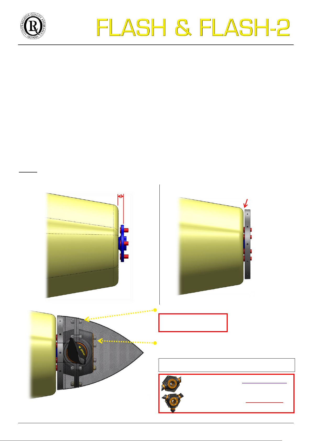
TIGHTENING TORQUE
3.0 Kg/m 30 N.m
5.2. Installation on the aircraft
Assembly of the two-blade or three-blade hub
Propeller fixing:
Screws CHC M8 & pin contact washer (length adapted
according the indexing paws of the propeller-shaft)
Threaded paws (Ex: ROTAX): Screw CHC M8x130mm
Ø8 hole paws (Ex: JABIRU): Screw CHC M8x140mm
14 mm
5 mm min.
TIGHTENING TORQUE TWO-BLADE HUB
2.5 Kg/m 25 N.m
As presented in section 4.1. Mounting configuration of the FLASH propeller, several mounting are possible:
1. Installing directly on propeller-shaft of the engine
2. Use a spacer for spacing propeller from the propeller-shaft
3. Use an adaptor spacer to adjust the diameter fixing of the propeller and for spacing the propeller from the
propeller-shaft
Direct installation on the aircraft 5.2.1.
The direct installation of the FLASH propeller is possible only with the following conditions:
Engine propeller-shaft type Rotax or Jabiru (6 indexing paws Ø13 or Ø14mm on P.C.D. Ø101.6mm/Ø4")
Engine propeller-shaft out of the engine hood of 14mm for the mounting of the DUC spinner
If needed, see in annex 11.1. Dimension of the engine propeller-shaft.
Remark: All engines having a propeller-shaft with a P.C.D. Ø101.6mm/Ø4" can install the FLASH propeller directly.
The holes of the metal inserts of the rear half-hub must be adapted to suit with the indexing paws of the
propeller-shaft. For further information, contact the DUC Propellers.
2.2 Kg/m 22 N.m
TIGHTENING TORQUE THREE-BLADE
11/28
Page 12
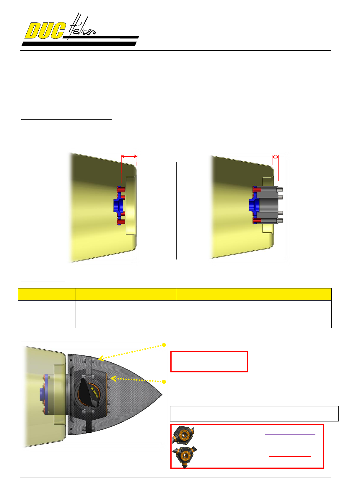
TIGHTENING TORQUE
3.0 Kg/m 30 N.m
Engine
Model
Length
ROTAX
912H spacer
6, 20, 30, 50, 60, 70, 80, 120mm
JABIRU
JABIRU spacer
6, 20, 30, 50, 60, 70, 80, 120mm
Assembly of the two-blade or three-blade hub
Propeller fixing:
Screw CHC M8 & pin contact washer (screw length adapted
according the length of the spacer)
Consult the installation instructions of the spacer for
more information.
Propeller-shaft not
outside the engine hood
14 mm min.
TIGHTENING TORQUE TWO-BLADE HUB
2.5 Kg/m 25 N.m
Use of an spacer 5.2.2.
A spacer is necessary in the following case:
Engine propeller-shaft type Rotax or Jabiru (6 indexing paws Ø13 or Ø14mm on P.C.D. Ø101.6mm/Ø4")
Engine propeller-shaft placed inside the engine hood or not place at more than 14mm
Determination of the spacer length:
Measure the distance X between the propeller-shaft and the engine hood limit, then add 14mm.
Available spacer:
Presentation of the installation
12/28
2.2 Kg/m 22 N.m
TIGHTENING TORQUE THREE-BLADE
Page 13
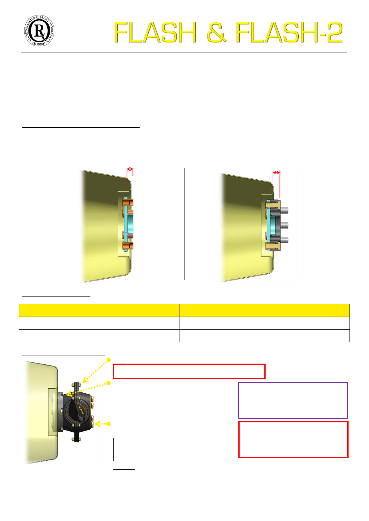
TIGHTENING TORQUE 3.0 Kg/m 30 N.m
Consult the installation instructions of
the adaptor spacer for more
information.
Use of adaptor spacer 5.2.3.
Engine
Model
Length
Continental O-200 / Lycoming O-233
SAE1 adaptor spacer
30, 70, 100mm
Lycoming O-360
SAE2 adaptor spacer
30, 70, 100mm
Assembly of the two-blade or three-blade hub
Fixation of the adaptor spacer
SAE1: Screw AN6 / SAE2: Screw AN8
(screw length adapted according the
adaptor spacer length and the starter
flange on the propeller-shaft)
Propeller fixing:
SAE1: Screw AN6-51 / SAE2: Screw AN8-51
Remark: It is imperative to use a spinner when using propeller FLASH.
The mounting plate of the spinner can be placed before or after the spacer
adaptation. It is necessary to adapt the mounting in function of its position.
Propeller-shaft not
outside the engine hood
14 mm min.
TIGHTENING TORQUE
ADAPTOR SPACER
AN6 (3/8"): 3.0 Kg/m 30 N.m
AN8 (1/2"): 4.5 Kg/m 45 N.m
TIGHTENING TORQUE
PROPELLER FIXING
AN6 (3/8"): 3.0 Kg/m 30 N.m
AN8 (1/2"): 4.5 Kg/m 45 N.m
An adaptor spacer is necessary in the following case:
Engine propeller-shaft different than the type Rotax or Jabiru (other than P.C.D. Ø101.6mm/Ø4")
If needed, see in annex 11.1 Dimension of the engine propeller-shaft.
Determination of the adaptor spacer length:
Measure the distance X between the propeller-shaft and the limit of the engine hood, then add 14mm.
Available adpator spacer:
Presentation of the installation
13/28
Page 14
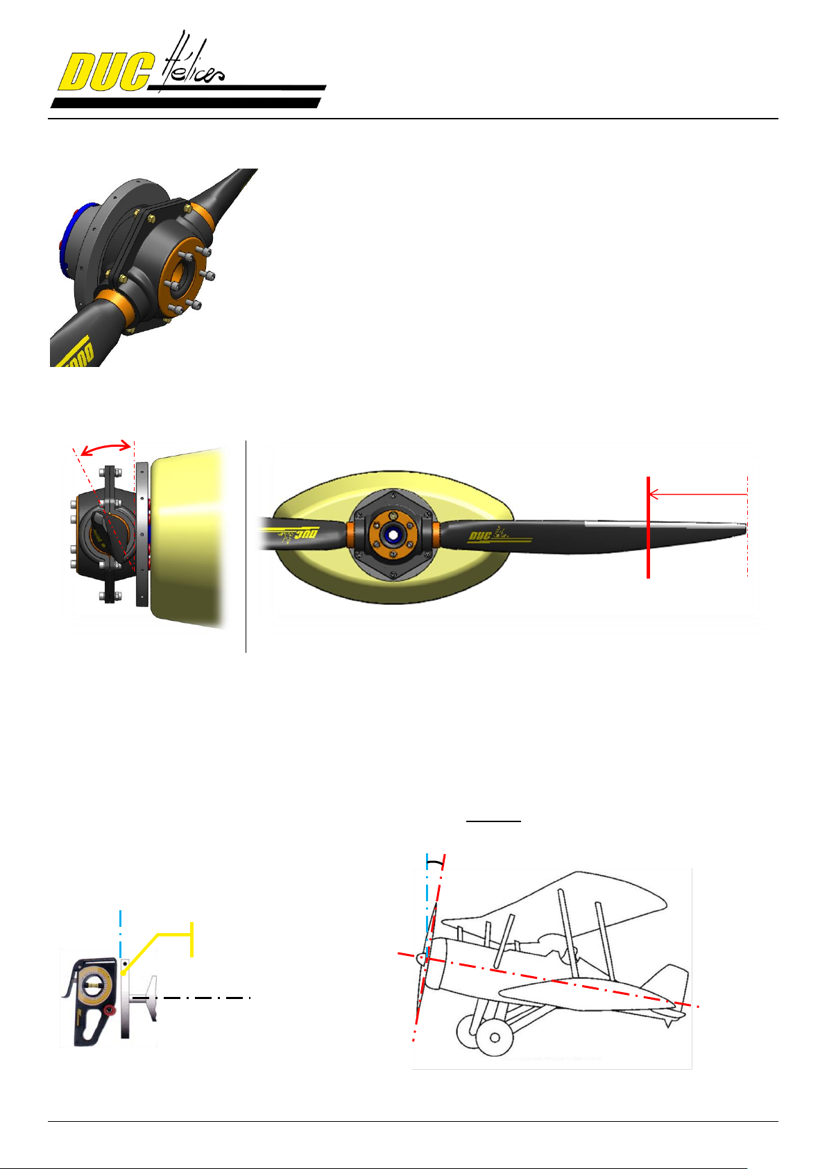
At this point, the propeller is installed on your aircraft with the spinner mounting
plate.
If the propeller is already assembled and the blades angle set, pass directly
STEP 7.
Otherwise, follow all the steps below to adjust the pitch angle before the final
tightening of the screw.
A reminder of the definition of the airfoil and its vocabulary is presented in annex
11.2. Airfoil.
Side view
Front view
90°
Propellershaft plate
0°
90°
(90° - X)
25 cm
5.3. Setting of the propeller & Finalization of the installation
STEP 1.
For the setting, the concerned blade must be place in horizontal position.
The setting is done with the adjusting tool flatten against the intrados (leading edge up) at 25 cm from the blade tip.
The attack angle is formed by the vertical and the intrados of the blade.
To do this, place your aircraft horizontally, so that the propeller shaft is perfectly vertical.
Check with the level of the adjustment tool (measured value = 90°). If unable to change the longitudinal axis of the
aircraft, raising the value of the X angle propeller shaft plate to subtract the value of the blade angle to be
resolved.
14/28
Page 15
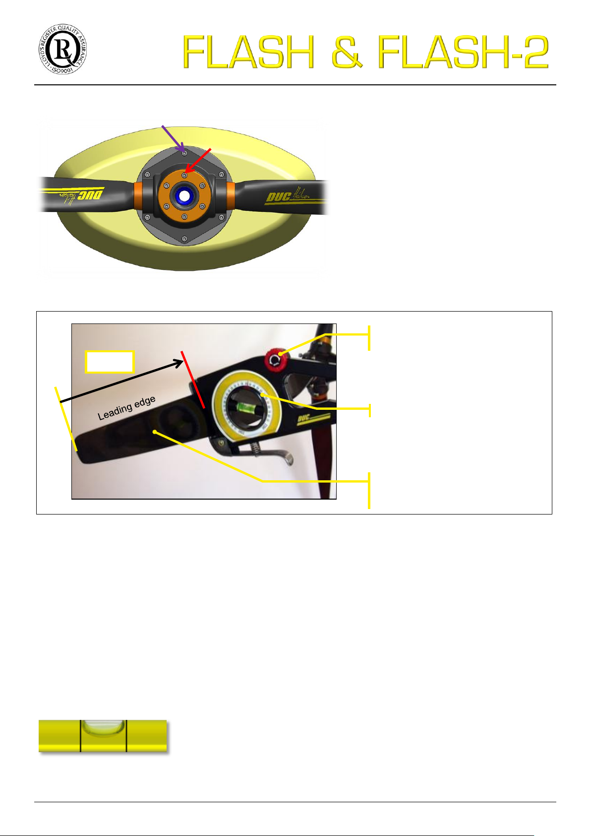
STEP 2.
Slightly untighten the propeller fixing screws
and the hub assembly screw.
The accuracy of the adjustment tool is 0.2°. This is defined by the tolerance of the
visual position of the bubble between the two lines.
Adjustment roller of the
leading edge
Reading blade angle
Intrados of the blade with the
leading edge upwards
Horizontal blade
25 cm
STEP 3.
Horizontal blade, leading edge upward, place the adjustment tool at 25 cm from the tip of the blade, intrados
side (flat), handle down.
STEP 4.
Set the desired value of the adjustment tool.
Caution to apply the value X if a correction of the aircraft plan was needed.
STEP 5.
Correct the position of the bubble on the adjustment tool by rotating the blade in the hub. To do this, using a mallet,
lightly tap on the foot of the blade in the desired direction.
Do not apply pressure near the trailing edge, thinner area.
15/28
Page 16
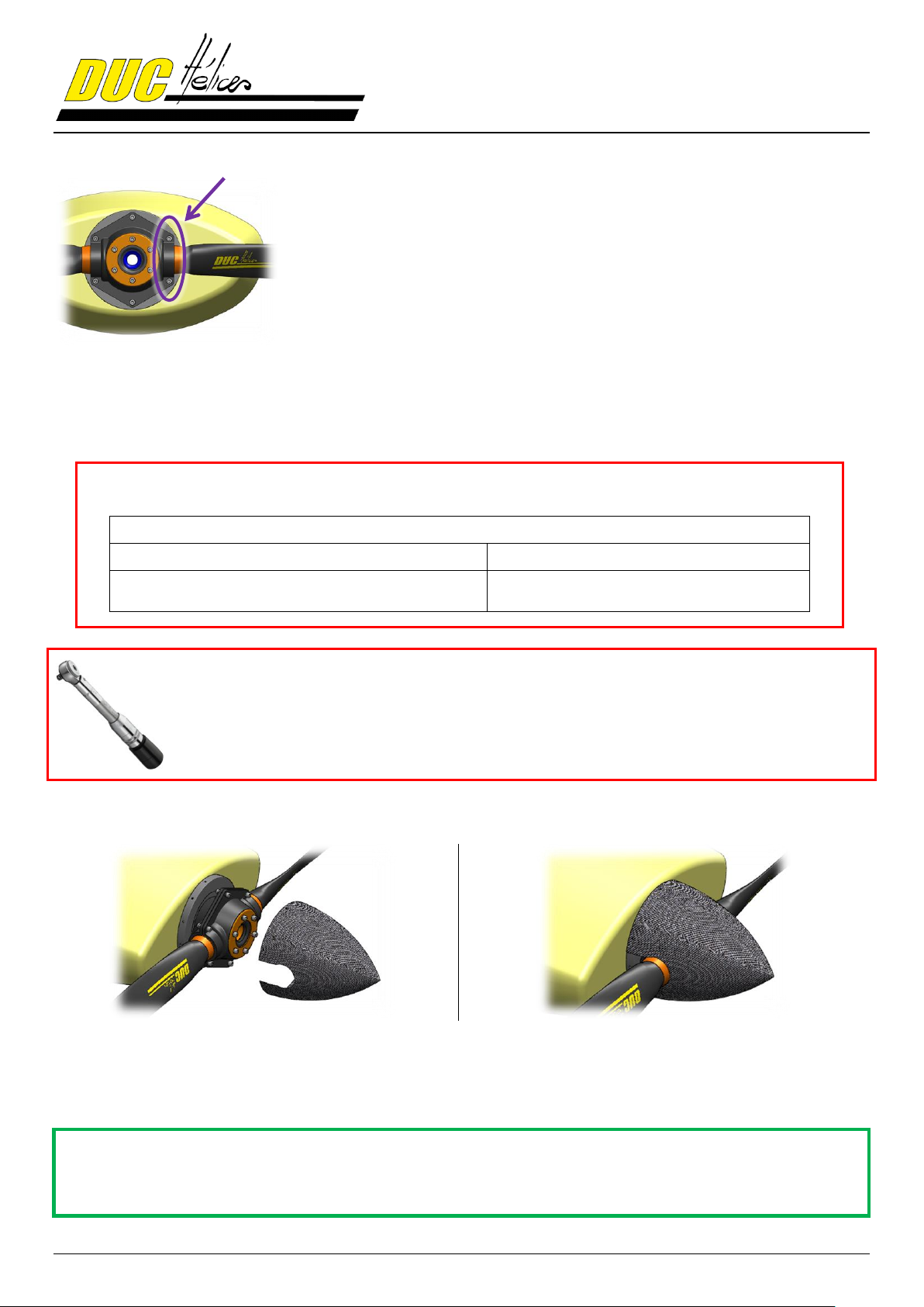
Once the desired pitch angle obtained, slightly tighten the assembly screws of
the hub, those around the foot blade and then perform the same operation on
each of the other blades.
IMPORTANT
After a 1 hour operation following the installation or modification of the
assembly, recheck the assembly of your propeller according the instructions
manual using appropriate tools (tightening torque, pitch angle…).
At this point, the FLASH propeller is ready for first tests.
TIGHTENING TORQUE
Screw assembly of the two and three-blade hubs = 30 Nm (3.0 kg/m)
Propeller fixing screws
Direct mounting/Spacer
Adaptor spacer mounting
Two-blade screw CHC M8 = 22 Nm (2,2 kg/m)
Three-blade screw CHC M8 = 25 Nm (2.5 kg/m)
Screw AN6 (3/8") = 30 Nm (3 kg/m)
Screw AN8 (1/2") = 45 Nm (4.5 kg/m)
STEP 6.
STEP 7.
Remove the adjusting tool from the propeller then perform a first tightening of the bolts manually.
Then, carry out a progressive tightening of all the screws by applying the correct torque with a torque wrench:
STEP 8.
After a final verification (position and orientation of parts, tightening...), mount the spinner on the mounting plate by
tightening the spinner screws to a torque of 4Nm (0.4kg/m) with the appropriate tools.
In the presence of a marking, please respect the indexing of the spinner from its plate.
16/28
Page 17
6. Precautions
IMPORTANT
After a 1 hour operation following the installation or modification of the
assembly, recheck the assembly of your propeller according the instructions
manual using appropriate tools (tightening torque, pitch angle…).
PRECAUTIONS
If you notice any abnormal installation or operation, do not undertake the flight and immediately contact the DUC
Hélices company.
Being aware of potential risks during assembly and initial testing of the propeller. Stay focused,
attentive and vigilant to your environment. Recheck several times points to be observed.
Maintaining high safety clearance during the set operation.
The products of the DUC Hélices company must be installed and used according to the instruction manuals provided.
No modification can be made without the agreement of DUC Hélices company. The non-compliance of these data
assumes no responsibility for the DUC Hélices company and makes out the warranty of the considered products (See
section 10. General terms of sale).
7. Indications for testing
INDICATIONS FOR TESTING
The tests are important. It is normal to make several adjustments successive alternating
ground and flight tests.
PRELIMINARY TEST to secure the 1st flight (Ground Test)
- Immobilized your aircraft, brakes locked. Apply the manufacturer's recommendations for safety.
- Turn the engine on, warm it up.
- Full throttle, the engine must be at least 85% of maximum engine speed recommended by the manufacturer in
flight. If this is not the case, adjust the blade pitch angle.
Increase pitch angle to reduce engine speed (and vice versa). 1° of pitch angle affects approximately 200 rpm engine
speed.
VALIDATION TEST of the pitch angle setting (Flight Test)
- Check all tightening. Take off and place the aircraft in stabilized flight, vario zero.
- To take off, it is not recommended to throttle, brake applied and then releases the brakes. You must put the
throttle gradually, brake released. The propeller has a constant speed effect, so this second way avoids
cavitation takeoff. Furthermore, this method allows shorter takeoffs.
- Full throttle, the maximum engine speed recommended by the manufacturer must be reached but not exceeded.
If this is not the case, adjust the blade pitch angle.
Increase pitch angle to reduce engine speed (and vice versa). 1° of pitch angle affects approximately 200 rpm engine
speed.
17/28
Page 18
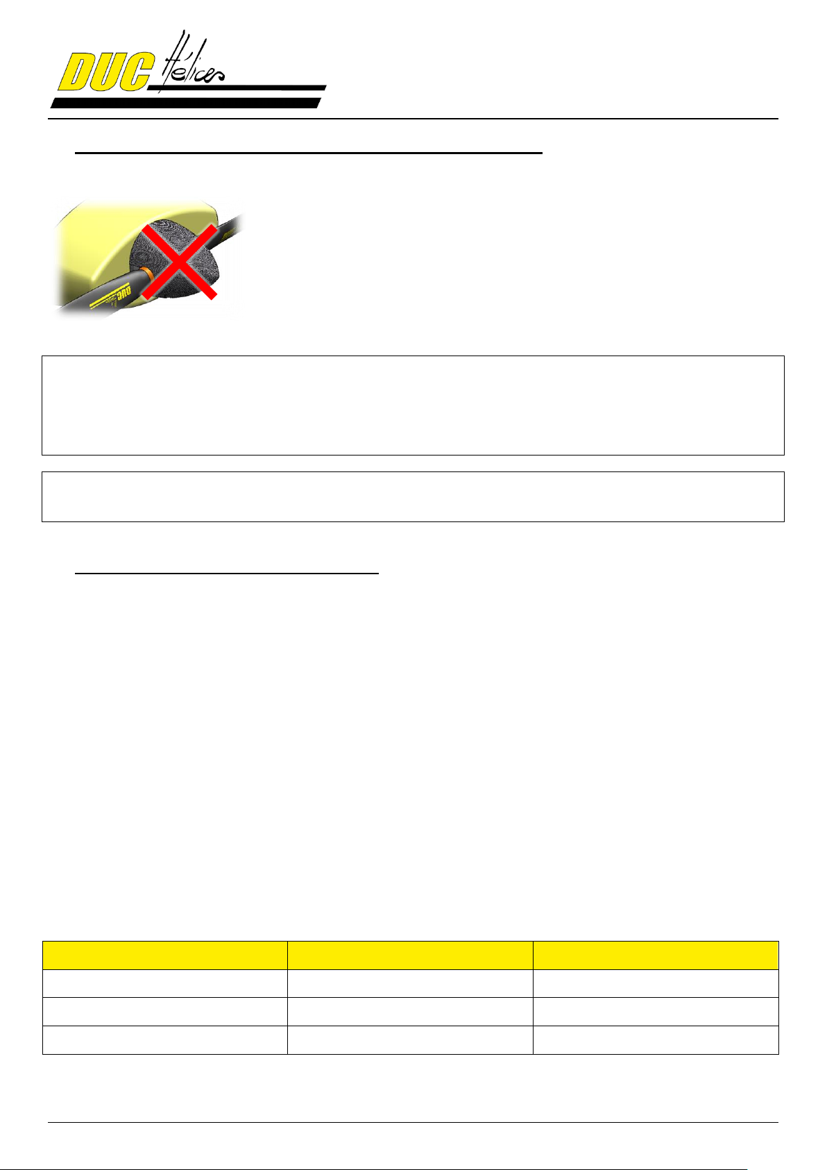
In the case of installation of the propeller without spinner mounting plate or other
spinner mounting plate, be careful to check the following points:
Length of the fixing screws of the propeller: Must be adapted according
the thickness of the spinner mounting plate.
Mechanical resistance of the plate when tightening: For a similar
assembly of the DUC spinner, the plate takes the tightening of the
propeller fixing screws. It is therefore necessary to ensure that the used
plate can withstand the clamping and resist of the propeller operate efforts
(crushing of the plate).
Type
Actor
Frequency
Regular
User
Each pre-flight
General
user or an aeronautics workshop
Every 100 hours or annually
Complete
DUC Hélices company
Each TBO
8. Installation without spinner or with spinner other than DUC
IMPORTANT
The spinner is an important element for engine cooling.
The aircraft must not fly without propeller spinner. Mounting a different cone will be an amendment to this instruction
manual approved by the DUC in order to confirm its compatibility mounting the propeller.
WARRANTY CONDITIONS
The user is still flying under its full responsibility (see section 10. General terms of sale).
9. Potential use & Propeller maintenance
9.1. Potential use of the propeller: Unlimited
The DUC propellers have an unlimited flight potential in normal operation.
To keep the unlimited potential, DUC Hélices has defined a TBO (Time Between Overhaul) for a propeller depending
on its engine. This TBO according the engine is indicated in this manual (see 2. Applications). In all cases, it may not
exceed 5 years.
When more intensive use (flight school...), the value of the TBO can be doubled maintaining control at least every 2
years.
To achieve this, we propose to return the propeller to make a full control and ensure its proper use.
If no critical anomaly is detected, it is again credited with the same TBO and is returned to you.
As a reminder, there is no imperative logbook. But know that this control is offered as a service to our customers for
continuing airworthiness and there is no obligation. In fact, security will not be affected.
The deliveries costs of sending and returning will be payable by the customer.
9.2. Propeller maintenance schedule
18/28
Page 19

9.1. Regular maintenance (by the user)
For a safety use of the FLASH propellers, it is necessary that the user performs regular maintenance to detect any
abnormalities. This maintenance is usually just a simple check.
Frequency of checking: Each pre-flight
Control methods: Visual inspection & Manual handling
Checkpoints:
- Fixation of the propeller: Manually maintaining the tip of a blade of the propeller, shake it firmly to feel if a
too much clearance appears in the setting of the propeller.
- Degradation of material: Check visually the entire propeller without dismantling (blade root, Inconel leading
edge, surface of the blade, spinner, hub, etc.)
- Fixation of the spinner: Check visually the fixation screws of the spinner. A marking paint can be made
between each screw and spinner to have a means of visual inspection of proper tightening the screws.
Possible problems:
- Too much clearance in the propeller fixation
- Surface degradation due to dirt or impact / Crack apparent
Corrective actions (depending on the importance):
1. Clean the propeller with the DUC cleaning treatment DUC (ref. 01-80-003)
2. Perform a repair with the DUC repair kit (ref. 01-80-004)
3. Tighten the screws to proper torque with wrench
4. Replace(s) damage component(s)
5. Contact DUC Hélices to define a solution
9.2. General maintenance (by the user or an aeronautics workshop)
A general maintenance by the user or an aeronautics workshop must be made at lower frequency.
Frequency of checking: Every 100 hours or annually
Control methods: Visual inspection & Torque wrench
Checkpoints:
- Fixation of the propeller: By removing the spinner of the propeller, check the proper tightening of the
screws to the wrench. These screws of the hub should be tightened to proper torque, defined in the
installation instructions attached.
A marking paint of all the screw/washer/hub after tightening can be done to help make a visual check
outside of the general maintenance.
- Degradation of material: Check visually the entire propeller (blade root, Inconel leading edge, surface of
the blade, spinner, hub, etc.)
Possible problems:
- Too much clearance in the propeller fixation
- Surface degradation due to dirt or impact / Crack apparent
Corrective actions (depending on the importance):
1. Clean the propeller with the DUC cleaning treatment DUC (ref. 01-80-003)
2. Perform a repair with the DUC repair kit (ref. 01-80-004)
3. Tighten the screws to proper torque with wrench
4. Replace(s) damage component(s)
5. Contact DUC Hélices to define a solution
19/28
Page 20

9.3. Complete maintenance (by DUC Hélices)
Upon reaching the TBO (potential flight time between overhaul) defined by DUC Hélices, the propeller must be
returned to the corporation for a full inspection of all components of the propeller.
See section 2. Applications for the potential value of an hour's flight engine.
The possible degradation of the propeller components may vary depending on the location of use.
10. General terms of sale
10.1. Ordering procedure
Orders placed by fax, by phone or mail server engage the customer upon receipt by our Customer Service Order and
the Regulations.
10.2. Delivery
DUC Hélices Company agrees to make every effort to deliver the order within the shortest time, and the receipt of the order
together with the Regulation. The delivery times indicated on the order are only indicative and the possible delays do not entitle the
buyer to cancel the sale, to refuse the goods or claim damages. Any claim for non-compliance or failure will be sent within one
week following the date of receipt of order.
The DUC Hélices Company is released from its obligation to deliver for all fortuitous events or force majeure. As an indication, the
total or partial strikes, floods, fires are cases of force majeure. The transfer of ownership of goods supplied or delivered is
suspended until full payment of price by the customer and without affecting the transfer of risk.
10.3. Price
The DUC Hélices Company may change its prices at any time.
The customer agrees to pay the purchase price in effect at the time of order entry. Regulation Order is payable in advance in one
payment when sending the DUC Hélices Company purchase order.
10.4. Right of withdrawal
Under Article L121-16 of the Consumer Code, the customer shall have seven clear days after the delivery of his order to return the
products to the DUC Hélices Company for exchange or refund, without penalties except for the return costs. Returned products
must not have suffered modification, damage consequence of shock or improper use and be packaged in original packaging.
Goods shipped with postage due will not be accepted.
10.5. Warranties
The DUC Hélices Company's products must be installed and used in accordance with instruction manuals provided. No changes
can be made without the prior approval of the DUC Hélices Company. The failure of these data releases any liability of the DUC
Hélices Company and makes non-warranty the considered products.
The user is still flying under its sole responsibility.
The legal guarantee of industrial products is six months or for the potential duration of the helix (depends on which engine it is
installed) against defects and hidden defects. See the section 2. Applications to determine the potential value of an hour's flight
engine.
DUC Hélices Company guarantees its product defect under normal use in the manner described below: If the customer finds a
defect, he must report it immediately to the DUC Hélices and features of one months after its purchase to return to society DUC
Helices, all structural defects will snuff into account (except for damage result of incorrect operation, shock, injury, impairment or
neglect, water or generally inappropriate use by the engine type, power, speed and gear). To qualify for this warranty, the customer
must send at its expense within one month after its purchase to be returned to society with DUC Hélices delivery order attached to
the product. In return, the DUC Hélices Company takes no responsibility for damage or loss during transit due to improper or
inadequate packaging. The company DUC Propellers then returned at his expense to the customer at the address on the delivery
note, an identical or equivalent.
In addition to these guarantees, the company DUC Hélices provides no other warranties.
10.6. Privacy Policy
All the data you entrust to us are able to process your orders. Under Law No. 78-17 of January 6, 1978 relating to data, files and
freedoms you have with the customer service company DUC Hélices right to access, review, correct, correct and delete data you
have provided.
10.7. Litigation
Any order placed convincing the customer, without any restriction, the General Conditions of sale of the DUC Hélices Company.
Any dispute concerning the sale (price, GTS, product ...) will be subject to French law before the Tribunal de Commerce de Lyon.
20/28
Page 21
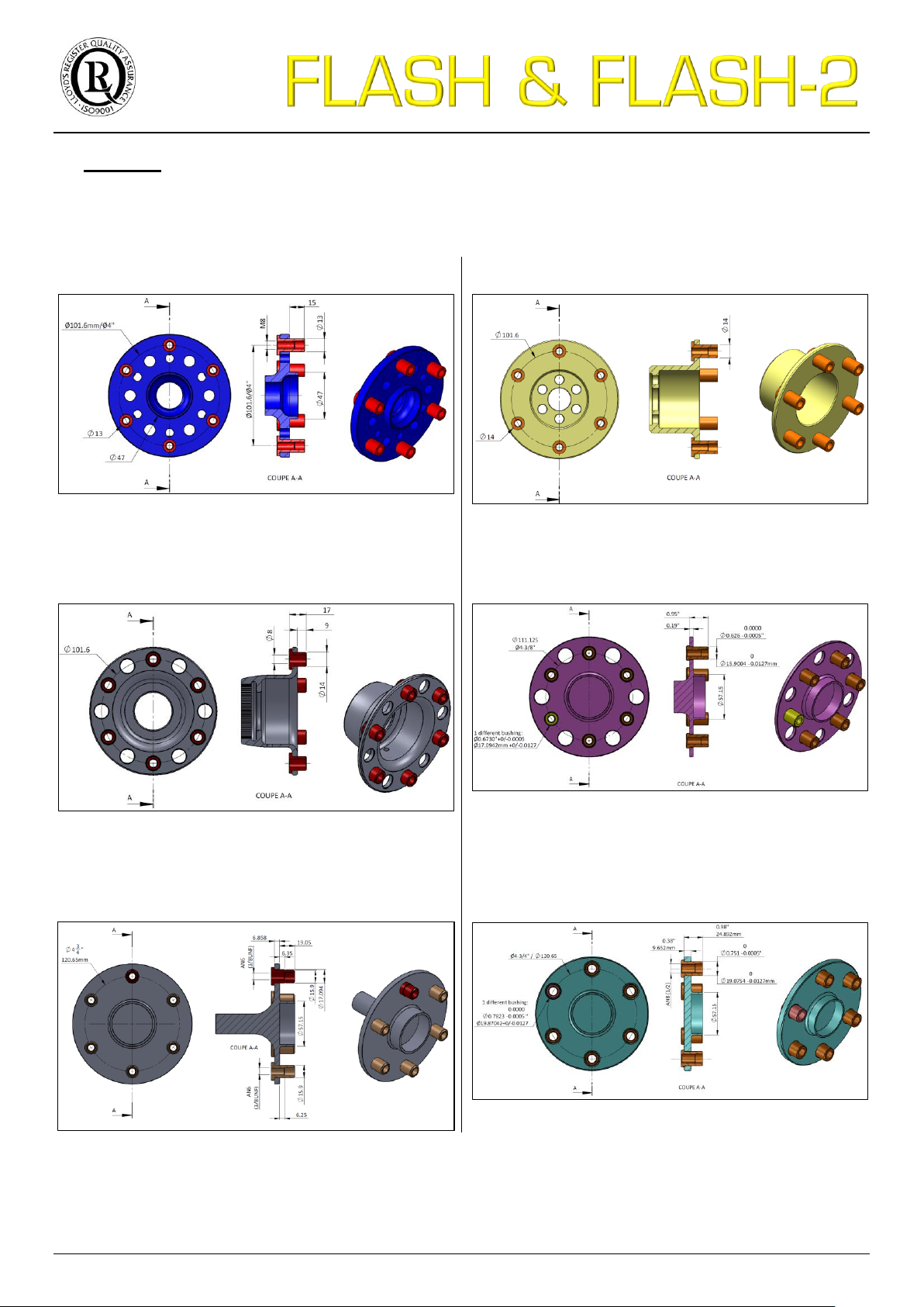
11. Annexes
ROTAX 912S engine propeller-shaft
JABIRU 2200 engine propeller-shaft
UL Power engine propeller-shaft
Lycoming O-235-H2C engine prop-shaft, type SAE 1
Lycoming O-320-A2A engine prop-shaft, type SAE 2
Lycoming O-360-A3A engine prop-shaft, type SAE 2
11.1. Dimension of the engine propeller-shaft
21/28
Page 22
Type of propeller
Diameter (mm)
Inertia (kg.cm²)
Three-blade Inconel FLASH
Left & Right
1620
3457
1660
3586
1700
3722
1730
3817
1750
3882
1850
4211
1900
4375
Designation
Maximum
engine power
Maximum
rotational speed
Two-blade Inconel FLASH propeller, Right & Left
140 hp
3400 rpm
Two-blade Inconel FLASH-R propeller, Right & Left
160 hp
3000 rpm
Three-blade Inconel FLASH propeller, Right & Left
160 hp
3400 rpm
Three-blade Inconel FLASH-R propeller, Right & Left
215 hp
3000 rpm
Three-blade Inconel FLASH-2 propeller, Left
160 hp
3400 rpm
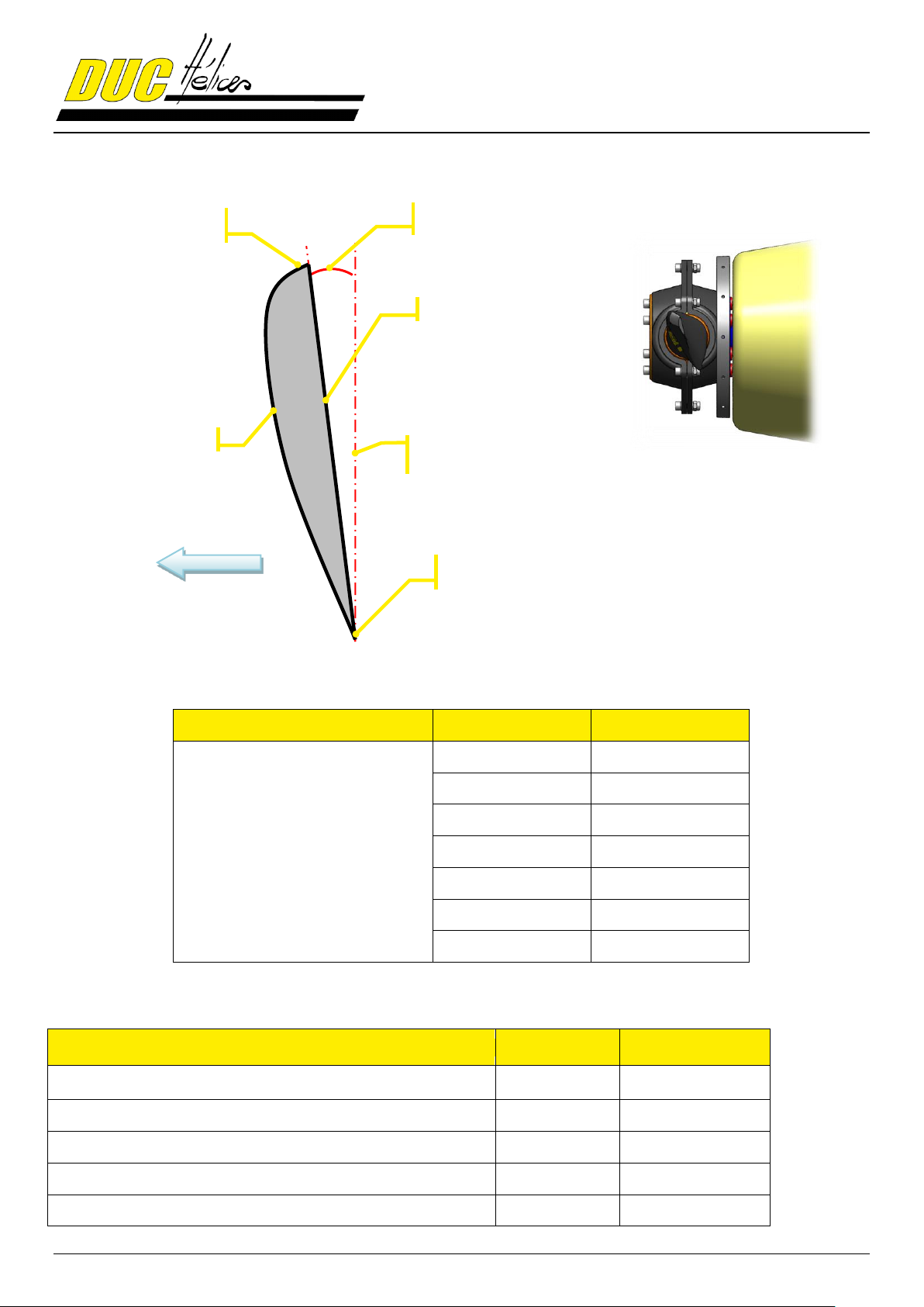
Axis of propeller carrier plate
completely vertical
Intrados
Extrados
Leading edge
Advancement of the aircraft
Trailing edge
Attack angle
Side view
11.2. Airfoil
11.3. Moment of inertia of the FLASH propeller
11.4. Operating limitation of the FLASH propeller
22/28
Page 23
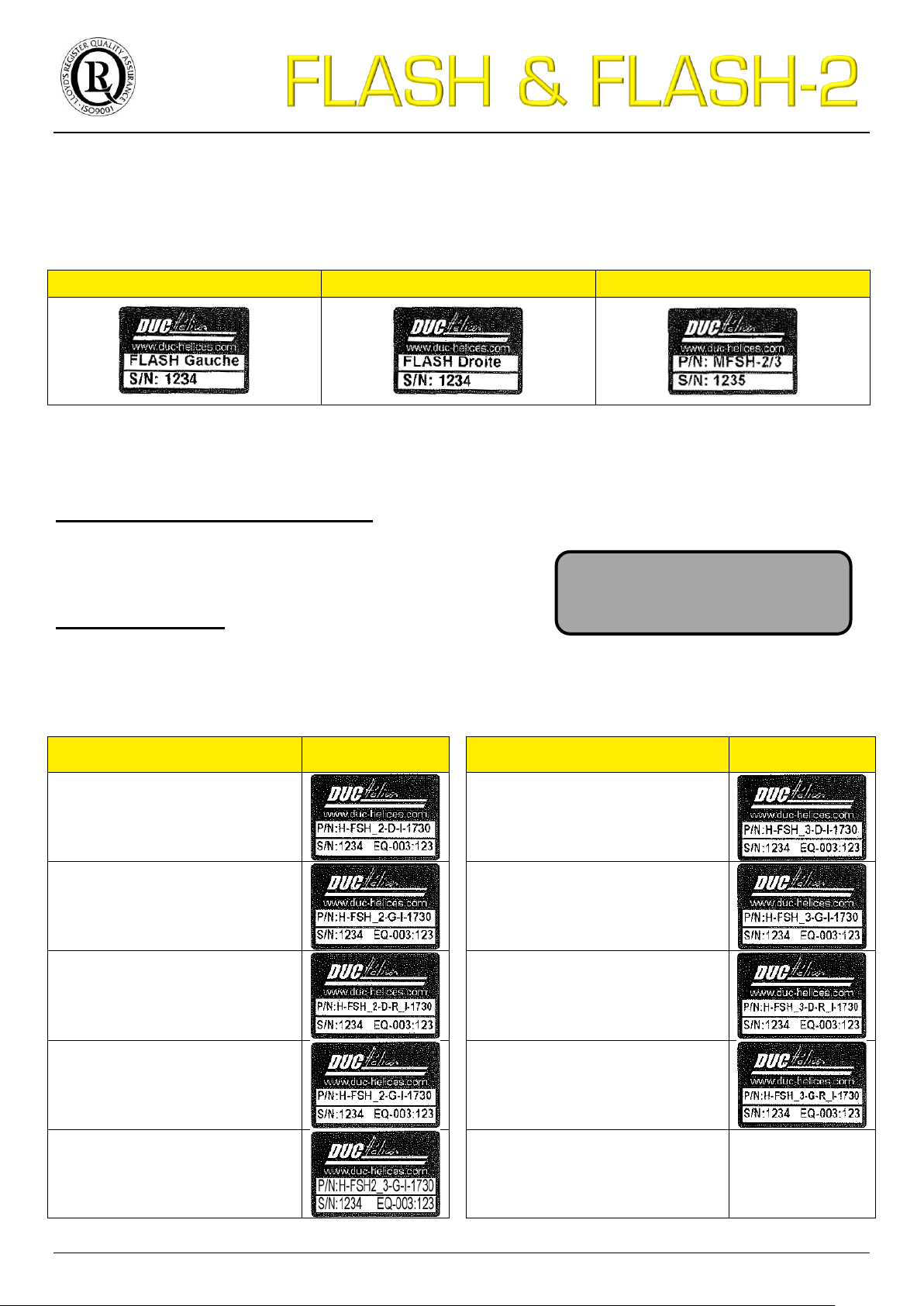
11.5. Identification marking of the propeller
FLASH Left blade (All version)
FLASH Right blade (All version)
Half-hub (2 and 3-blade)
1st line: Part number of the propeller model
Two-blade (2) or Three-blade (3)
Left (G) or Right (D)
Reinforced structure (R) and/or Inconel leading edge (I)
Diameter in mm
2nd line : Propeller data
Serial number of the propeller (not only the component)
Value of the static balancing of each blade of the prop
Propeller version
Label Propeller version
Label
Two-blade Inconel FLASH
propeller, Right
Three-blade Inconel FLASH
propeller, Right
Two-blade Inconel FLASH
propeller, Left
Three-blade Inconel FLASH
propeller, Left
Two-blade Inconel FLASH-R
propeller, Right
Three-blade Inconel FLASH-R
propeller, Right
Two-blade Inconel FLASH-R
propeller, Left
Three-blade Inconel FLASH-R
propeller, Left
Three-blade Inconel FLASH-2
propeller, Left
P/N: H-FSH_3-D-R_I-1730
S/N: XXXX EQ-003: XX
Manufacturing label 11.5.1.
As the propeller is dismountable, each component (blade and half-hub) has a manufacturing traceability label which
identifies the component and specifies its own serial number:
Propeller label (for LSA certified version) 11.5.2.
At the end of the manufacturing, a 2nd label - the propeller label - is placed on each components of the propeller (blade
and half-hub) with the following information:
Here is an example for each versions of the FLASH propeller possible:
23/28
Page 24
ENGINE
PROPELLER
CENTRIFUGAL FORCE
Type
RPM
max
(rpm)
Red.
RPM
Red
(rpm)
Ø
hélice
(mm)
G
pale
(mm)
R
G
(mm)
V
( m/s )
M
(kg) F (N)
F
FoS(2)
(N)
ROTAX 912
6000
2.273
2643
2-Ø1730
209
263.6
72.93
1.020
20 578
41 157
ROTAX 912S/914
6000
2.43
2469
3-Ø1730
209
263.6
68.12
1.020
17 958
35 916
F
FoS(2)
: Centrifugal force with factor of
safety 2 (RPM)
RPM
max
: Maximum engine speed (RPM)
Ø
hélice
: Propell er diameter (mm)
F : Centrifugal force (N)
G
pale
: Gravity center position on the blade (mm)
RPM
red
: Propell er rotation s peed (RPM)
RG : Radius of the gravity center of the blade (mm)
Red. : Gear box ratio
F
FoS(2)
: Centrifugal force with factor of
safety 2 (RPM)
F : Centrifugal force (N)
M : Weight of the blade (kg)
F
FoS(2)
: Centrifugal force with factor of
safety 2 (RPM)
Ø
hélice
: Propell er diameter (mm)
F : Centrifugal force (N)
G
pale
: Gravity center position on the blade (mm)
RG : Radius of the gravity center of the blade (mm)
V : Linear s peed in tip bl ade of the propeller (m/s)
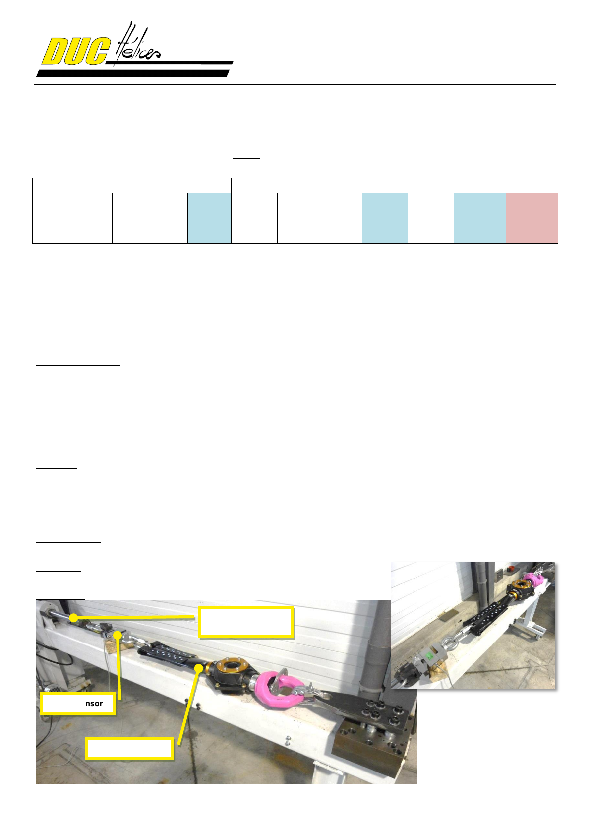
Force sensor
Tested propeller
Traction hydraulic
actuator
11.6. Calculation of the centrifugal force of the FLASH Inconel blade
The centrifugal force undergoes by the FLASH blade was calculated for the most soliciting configuration, i.e. engine
Rotax 912 (80hp).
Calculation of the centrifugal force:
11.7. Centrifugal force test under EASA CS-P350 specification
Standard reference:
EASA Certification Specifications for Propeller CS-P
Test method:
The test of centrifugal force propeller is defined by the certification specification of propeller CS-P 350. Its objective is
to demonstrate its compliance with the certification specification of propeller (CS-P) defined by the European Aviation
Safety Agency (EASA). After the test, the propeller must show no evidence of fatigue, failure or permanent
deformation that would result in a major or hazardous effect on the propeller. It is considered that this test is used to
validate the mechanical strength of the propeller, i.e. to confirm the manufacturing process thereof.
Objective:
This test is conducted with the Inconel FLASH propeller, Ø1730mm which is representative of its mounting on the
engine Rotax 912 (80hp). This engine is the most penalizing for the propeller due to its rotation speed.
Thus, the test is used to validate all configurations below that selected. In addition, all using the same propeller design
and the same manufacturing technology will be considered consistent with values similar or lower than those of the
test.
Tested sample:
Two-blade Inconel FLASH propeller Ref. 01-19-001 P/N: H-FSH_2-D-I S/N: 003
Procedure:
Applying a charge for 1 hour = 2 x maximum centrifugal load = 41 157 N
Test bench:
24/28
Page 25
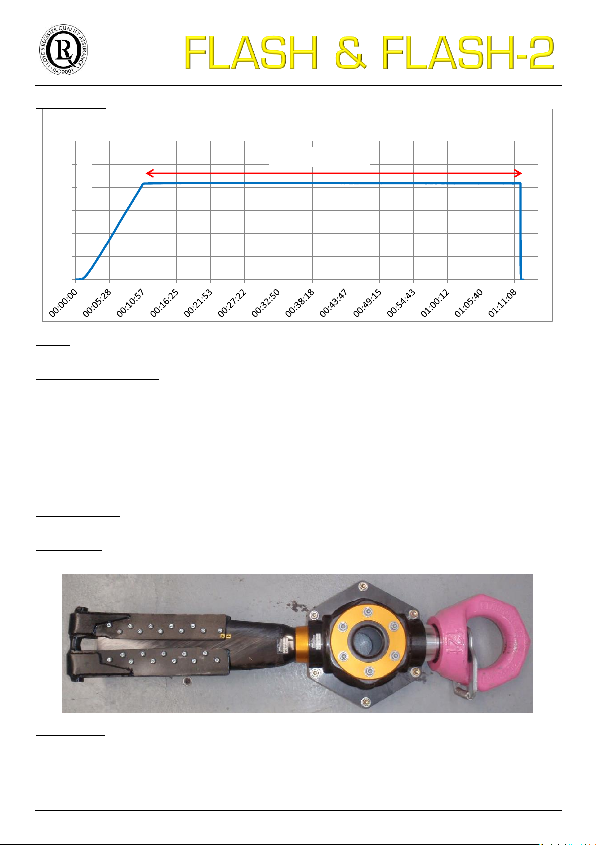
Test performing:
0
1 000
2 000
3 000
4 000
5 000
6 000
Force (dN)
Time
FLASH Centrifugal force test (CS-P350)
1 hour at 42 000 N
Results:
Obtained by visual analysis, no damage or failure was observed during and after the centrifugal load test.
Declaration of conformance:
The centrifugal load test according to specification EASA CS-P 350 leads to the conclusion that the propeller
is properly sized and is designed to operate on a similar installation (or less soliciting) of ROTAX 912 engine,
soliciting the blade in a centrifugal force of 20 578 N.
11.8. Breaking test of the two-blade Inconel FLASH propeller
Reference:
Extract from the SOPAVIB test report n° R6375973-002-1
Purpose of the test:
Tensile test to rupture
Tested sample:
Two-blade Inconel FLASH propeller Ref. 01-19-001 P/N: H-FSH_2-D-I S/N: 003
Testing method:
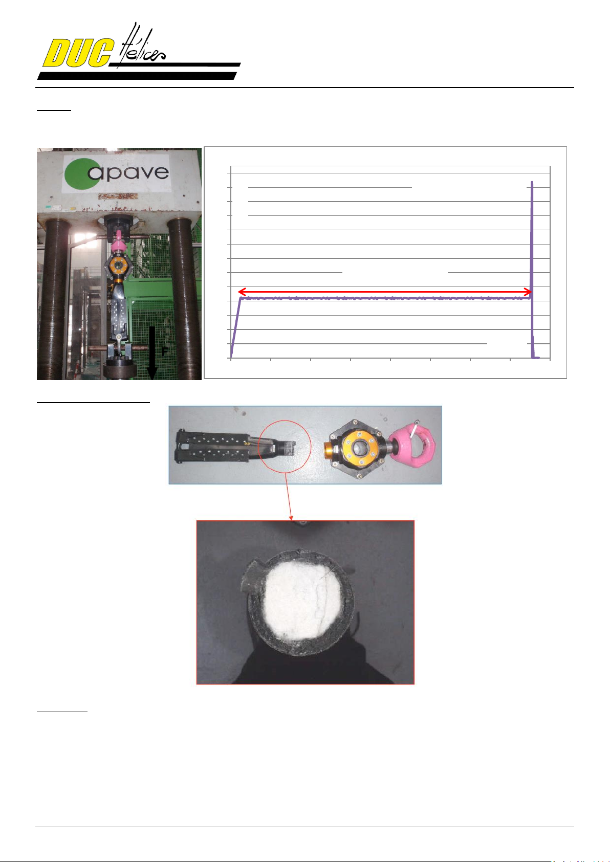
The tested propeller is placed between the fixed part and the movable part of the lab bench traction. Applying of the
following sequence:
Progressive increase of the load of 42 000 N in 120s (350N/s)
Hold 42 000 N during 60 minutes
Progressive increase of load to reach the break
25/28
Page 26
0
10
20
30
40
50
60
70
80
90
100
110
120
130
0 500 1000 1500 2000 2500 3000 3500 4000
Force (kN)
Time (s)
FLASH breaking test
1 hour at 42 000 N
Breaking at 123 758 N
Results:
At the end of the level at 42 000 N, no defect was found. The test was continued until failure.
The curve below shows the traction load applied to the propeller according the time.
Analysis of the specimen
Conclusion
The failure of the blade occurred at the foot, like expected, to an effort of 123.7 kN, i.e. more than 12 tons of load.
However, it was found in annex 11.6 Calculation of the centrifugal force of the FLASH Inconel blade that the
maximum effort in centrifugal, with safety factor of 2 (the standard required under EASA CS-P350), does not exceed
41 157 N.
Therefore, we can confirm the correct size of the FLASH propeller for all applications with a safety factor of 6.
26/28
Page 27
11.9. Declaration of conformance of the FLASH propellers
Design and Construction 11.9.1.
The propellers FLASH were designed to be adapted to the applications described in section 0. Every design features
are reliable and mastered by DUC Hélices company.
The materials used in the propeller were selected for their technical properties to be conforms to the definition of the
propeller and durable during the propeller life.
About the ground adjustable system, the design allows a fine and careful setting of the propeller blade pitch. Also, the
system is robust to not change during normal and emergency operation of the propeller and also after many settings.
Definition FLASH propeller conforms to withstand the stresses of operation on all its lifetime. Refer to the centrifugal
force test (section 11.6 & 11.7), breaking test (section 11.8) and next section 11.9.2. Tests and Inspections.
Tests and Inspections 11.9.2.
The FLASH propeller completes the tests and inspections described below, without failure or malfunction.
Strength Testing:
Proof of strength is presented in section 11.7. Centrifugal force test under EASA CS-P350 specification.
The blade root and blade retention system were tested for 1 hour at a load level equal to two times the centrifugal load
that would be generated by the blade weight at maximum rated rotational speed. This test was done in a static pull
test.
Endurance Testing:
The FLASH propeller conforms to endurance test of each application exposed in section 0.
Teardown Inspection:
After completion of each test described above, the tested FLASH propeller was completely disassembled and each
propeller parts were inspected. No failure or crack was found.
Propeller Adjustments and Parts Replacements:
During the tests and inspections carried out, no parts have to be repaired or replaced. All propeller parts resisted the
tests and were conform after inspections.
Design Control 11.9.3.
The FLASH propeller was design on CAD software. All the CAD files and 2D drawings are stored in the Design Office
of DUC Hélices Company, as the definition of the FLASH configurations. All the technical data (dimensions, materials
and processes) are saved in manufacturing procedure. Also, a copy all these data are archived out of the company.
Quality Assurance 11.9.4.
DUC Hélices Company is ISO 9001:2008 certified for its management of the quality system, which ensures
manufactured propellers maintain conformity to the established design. Refer to page 2.
Certification of Conformity for ASTM F2506-10 11.9.5.
“ASTM F2506-10 is the standard specification for design and testing of fixed-pitch or ground adjustable for Light Sport
Aircraft propellers.
DUC Hélices Company declares that the FLASH propeller complies with the ASTM F2506-10 standard and after
verification, it responds every requirement.”
Mr. Vincent Duqueine
Manager
27/28
Page 28
Chemin de la Madone - 69210 LENTILLY - FRANCE
Tél. : + 33 (0)4 74 72 12 69 - Fax : +33 (0)4 74 72 10 01
E-mail : [email protected] - www.duc-helices.com
S.A.V. : [email protected]
Entreprise certifiée
ISO 9001:2008
Neoprene cover – Commercial reference: 01-80-002
Degrease your propeller
REDUCE CONSUMPTION
by improving performance
Commercial reference: 01-80-003
Data and pictures included in this instruction manual are exclusively property of DUC Hélices Company. Any part of this manual can be
reproduced or transmitted in any form with any means, electronic or manual, for any reason, without written approval of DUC Hélices
Company.
 Loading...