

DUCATIHOME 8500V-Rol/ DUCATI UP 70 (CTH29E) Installation Instructions Manual
Page 1D
DHA srl
via Agrate 99/7
20863 Concorezzo (MB) Italy
Tel. +39/039/9633200
Fax +39/039/9633219
service@ducatihome.it
www.automaticgateshop.com
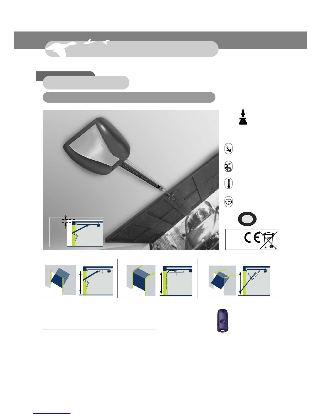
Garage door automation system 70 kg
Rev.06/08 ENG
Installation instructions
Read all of these instructions carefully before commencing
installation. For any further information, please contact the
manufacturer: Allducks
max. 8 m
2
100 kg
Kg
G
A
A
N
Z
I
A
*
G
A
R
A
N
T
I
E
*
2
Ans
Power supply
230 V/ 50 Hz W60
8–24 V dc
Motor
-10 °C / + 50 °C
Operating temperature
11–18 sec.
Opening/closing time
MADE IN ITALY
RoHS
IMPORTANT:
The door must slide smoothly and be well balanced.
Canopy doorRetractable door Sectional door
max.
h 2,30 m
MAXIMUM HEIGHT OF DOOR
Min.
5 cm
8500V-Rol/ DUCATI UP 70 (CTH29E)
max.
h 2,15 m
max.
h 2,15 m

Page 2
Contents
Introduction
Assembly
Fixing
Rolling code remote
control
Power adjustment
1. Contents of kit . . . . . . . . . . . . . . . . . . . . . . . . . . . . . . .page 3
2. Technical data . . . . . . . . . . . . . . . . . . . . . . . . . . . . . . .page 3
3. Types of door . . . . . . . . . . . . . . . . . . . . . . . . . . . . . . . .page 4
4. Installation criteria . . . . . . . . . . . . . . . . . . . . . . . . . . . .page 5
5. Installation diagram . . . . . . . . . . . . . . . . . . . . . . . . . .page 6-7
6.1 Assembly of the “U” channel rail . . . . . . . . . . . . . . . . . .page 8
6.2 Return pulley and preassembled accessories . . . . . . .page 8
6.3 Assembly of the chain . . . . . . . . . . . . . . . . . . . . . . . . .page 9
6.4 Assembly of the drive plate . . . . . . . . . . . . . . . . . . . .page 10
7.1 Fixing to the door lintel . . . . . . . . . . . . . . . . . . . . . . . . page 11
7.2 Fixing the drive head . . . . . . . . . . . . . . . . . . . . . . . . . page 11
7.3 Fixing to the door . . . . . . . . . . . . . . . . . . . . . . . . . . . . page 12
7.4 Chain tensioner . . . . . . . . . . . . . . . . . . . . . . . . . . . . . page 12
Release
8. Manual release . . . . . . . . . . . . . . . . . . . . . . . . . . . . . .page 13
End of travel
9. Adjusting the mechanical end-of-travel stop . . . . . . . .page 14
Power supply
connection
10. 230V power supply connection . . . . . . . . . . . . . . . . . .page 14
11. CTH29E circuit board . . . . . . . . . . . . . . . . . . . . . . . . .page 15
12. A) Storing the transmission code . . . . . . . . . . . . . . . .page 16
12. B) Erasing codes from memory . . . . . . . . . . . . . . . . .page 16
13. Power adjustment . . . . . . . . . . . . . . . . . . . . . . . . . . . .page 16
Accessoires
14. Optional accessories . . . . . . . . . . . . . . . . . . . . . . . . .page 17
Troubleshooting
16. Quick troubleshooting: . . . . . . . . . . . . . . . . . . . . . . . .page 17
CE Conformity
17. Declaration of conformity . . . . . . . . . . . . . . . . . . . . . .page 18
Guarantee and
After-Sales Service
18. Guarantee and After-Sales Service . . . . . . . . . . . . . .page 19
Spare parts
Spare parts . . . . . . . . . . . . . . . . . . . . . . . . . . . . . . . . . . . . .page 19
Page 3
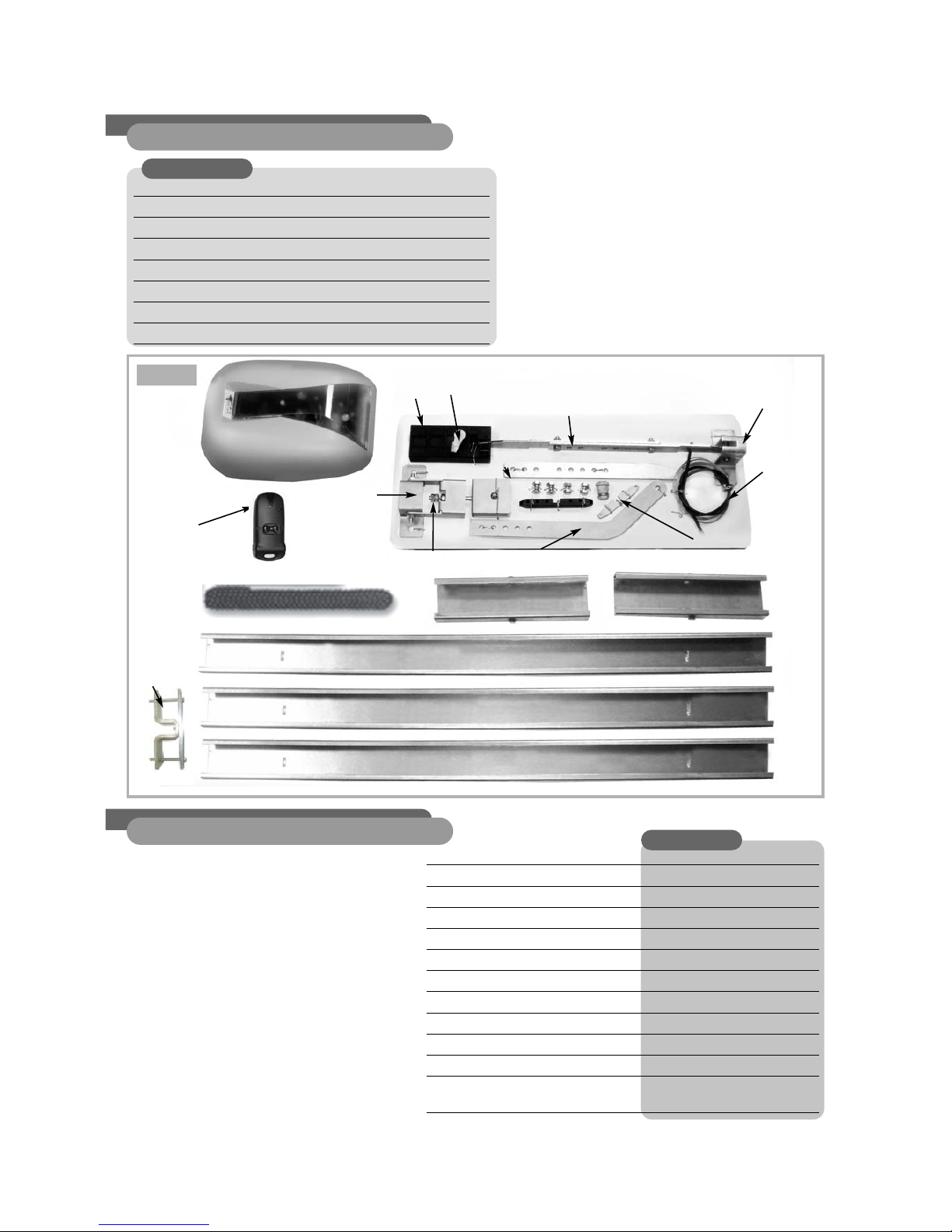
1. Contents of kitUP70
kit UP 70
Power supply* ( Vac 50/60/Hz) 230V
Lifting force (N) 70
Absorbed power (W) 80
Toroidal transformer 105W
Protection fuse 0.8A T
Radio frequency 433 MHz
Speed (m/sec.) 0.15
Operating temperature (°C min/max) -10/+50
Courtesy light Yes
Amperometric safety system Yes
Power adjustment with trimmer
End of travel amperometric detection
+ end of travel open position
2.Technical data
Geared motor unit 24V d.c.
CTH29E circuit board
1 x 2-channels rolling code 433 MHz remote control
Chain drive
270 cm “U” channel rail ( 3 x 90 cm) + 2 sleeves
manual release system
Nuts and bolts and preassembled accessories
Installation instructions
8500V-UP 70 -UP70 kit
Fig. 1
Geared motor unit
(drive head) trolle
Preassembled Ref. 812 connecting
rods for standard retractable door
release lever
chain anchor plate
chain
motor securing brackets
door fixing
plate
no. 1 remote control
Ref. 6203/ rolling
code
door lintel
fixing plate
chain tensioner
release
cable with
sleeve
sectional door accessory
#992014
“U” channel guide
Ref.829
“U” channel guide
Ref.829
“U” channel guide
Ref.829
Connecting sleeve
Ref. 830
Connecting sleeve
Ref. 830
mechanical
travel limiter
in door open
position
Page 4
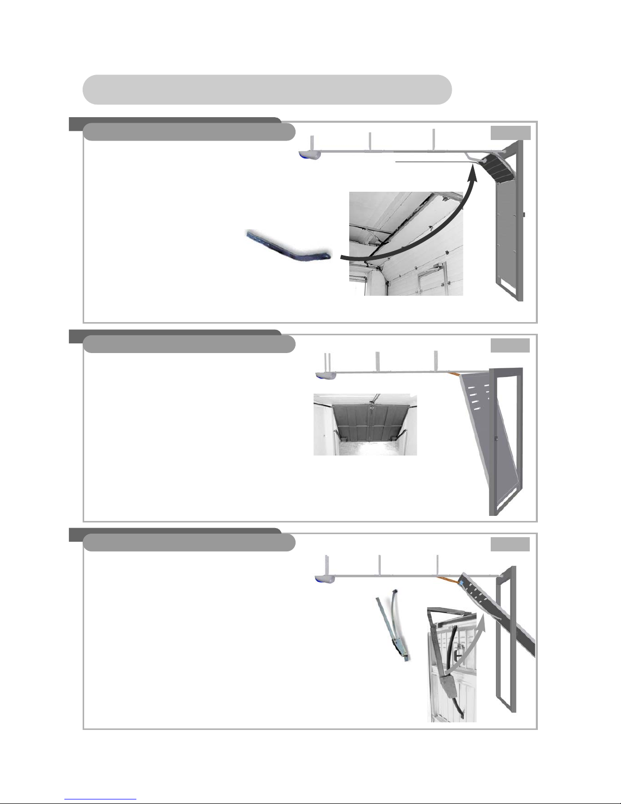
3. Types of door
For installation on a retractable door, no
additional accessory is required.
For installation on a canopy door, it is
necessary to add optional accessory: Ref.
992012*
For installation on a sectional door, it is
necessary to use accessory Ref. 992014,
which is supplied in the kit. Install the
accessory on the door fixing plate to replace
one of the two preassembled Ref. 812
connecting rods for standard retractable doors.
The canopy door accessory Ref. 992012 must
be purchased separately and is not included in
the kits. Specific installation instructions are
supplied with the accessory.
This item can also be purchased on the
www.allducks.it website, in the accessories
section.
Sectional door accessory: Ref.
992014 is supplied in the kit
Fig. 3
Fig. 4
Fig. 2
IMPORTANT:
La port doit avoir un mouvement glissant, et
être bien équilibrée!
IMPORTANT:
The door must slide smoothly and be wellbalanced!
IMPORTANT:
The door must slide smoothly and be wellbalanced!
3.1 Sectional door
3.2 Retractable door
3.3 Canopy door
Page 5
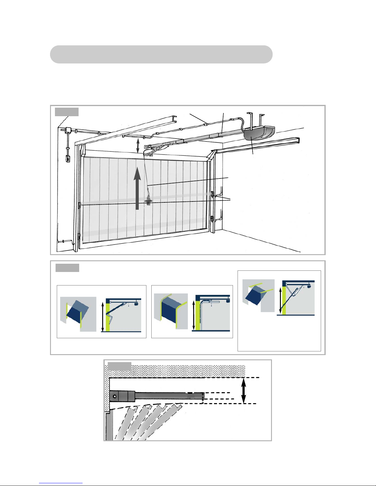
4. Installation criteria
Set of photoelectric cells (optional accessory not
included in the kit)
Drive head – geared motor unit complete with
circuit board
Manual release cable connected to the door handle
for external operation.
“U” channel rail
Distance: min.5 cm
Power supply 230V - 50/60 Hz
ceiling
rail
Min. 5 cm
To fix the automation system’s “U” channel rail it is necessary to have a minimum clearance of 5 cm
between the ceiling and the space through which the door moves.
A minimum distance of 1 cm is necessary between the position of the “U” channel rail and the space
through which the door moves. See fig. 7
Fig. 5
Fig. 6
Fig. 7
rail=3 cm
Min. 1 cm
Lifting force
= 100 N MAX
Canopy door
IMPORTANT: for installation
on this type of door, optional
accessory 992012 is
necessary
Retractable door
max.
h 2,15 m
Sectional door
max.
h 2,15 m
max.
h 2,30 m
MAXIMUM DOOR HEIGHT

Page 6
90 cm
5. Installation diagram
Fig. 8
 Loading...