

Page 1

Counterweighted / projecting up and
over door*
*= need extra accessory
canopy arm part#992012 not included in
the kit
Standard door
Page 1
Rév.1008 ENG
Assembly instructions
<700
max. m
2
Max traction
force: 0 kg
Kg
max.
h 2,15 m
Sectional door
max.
h 2,15 m
max.
h 2,30 m
Min.
5 cm
Power;
230 V/ 50 Hz
8-24 V dc
Gear
11-18 sec.
Opening time
WA R N I N G :
Carefully read this mounting instruction before installation.
In case you should require further informations, contact the manufacturer :
WA R N I N G :
Only to be installed on well balanced doors.
UK HELP-LINE:
LQIR#GXFDWLKRPHLW
7/24h help service
Ph.+39-3351022019
24V belt driven Garage door opener
MADE
IN ITALY
Page 2

Page 2
Index
CHAPTER CONTENTS PAGE
WARNING 3-4
1. Kit contents 5
2. Technical specifications 5
3. Garage door types 6
3.1 Standard non projecting up-and-over door 6
3.2 Sectional door 6
3.3 Projecting up-and-over door 6
4.
Operating limits & Installation Scheme 7-9
5
. Assembly instructions 10-12
6
. Fixing instructions 13-14
7. Manual release 15
8. 230V power supply 16
9. Remote control coding 17
10. Power adjustment 17
11
. Electronic board CTH29S 18
12.
. Setting the travel limits 19
13. Automatic closing 20
14. Maintenance 20
15.. Quick help to problem solving 20
16.
Warranty & After Sale service 21
17. Spare parts 21
18.
. Extra optional accessories 21
19.. Declaration of conformity 22
Page 3

Page 3
This garage door opener has been designed and tested to offer safe service provided it is installed, operated, mantained and tested in strict accordance with the instructions and warnings contained in this
manual.
Please, carefully reat this instruction manual before to procede with installation of your garage door opener, and make sure that weight , dimension and type of your garage door are within the limits of your
garage door opener model.
The structure of the door and the wall/pillars must be safe and stabile.
Install garage door opener only on properly balanced and lubricated garage door.
All repairs to cables, spring assemblies and other hardware must be made by a trained and professional
door systems technician BEFORE installing the garage opener
To prevent possible serious injury or death: always call a trained and certified door systems tecnician if
garage door binds, sticks or is out of balance.
An unbalanced garage door may not reverse when required and could result in serious injury or
death !
Never try to loosen, moove or adjust garage door, door springs, cables pulleys, bracketts or their har-
dware, all of wich are under EXTREME tension.
Disable all locks and remove all ropes connected to garage door before installing and operating garage
door opener to avid entanglement.
To prevent damage to garage door and opener: Always disable locks before installing and operating the
opener.
Never wear watches, rings, or loose clothing while installing or servicing opener. They could be caught
in garage door opener mechanisms.
Place entrapment warning labels on wall next to garage door control.
Place manual release/safety reverse label in plain view on inside of garage door.
Upon completion of installation, test that your garage door opener is corretly working and test safety
reversal system. door must reverse on contact with an object on the floor.
In order to prevent injuries:
Never leave childrens without parental control in proximity of a garage door opener in motion open, closed or stopped.
Never permit children to play with remote control push buttons or transmitters of garage door opener
and prevent childrens to operate the garage door opener by control push buttons or transmitters
.Always keep remote controls out of reach of children.
Install wall-mounted garage door controls ( optionals) out of reach of children and away
of moving parts
of the door.
Activate door only when it can be seen clearly, is properly adjusted and there are no obstructions to
door travel.
Always keep garage door in sight until completely closed.
Very Important Safety WARNINGS
!
!
Page 4

Page 4
Never permit anyone to cross path of closing garage door.
No one should go under a stopped, partially opened garage door.
Always make sure to have connected the unlocking cable in order to
permit to manually unlock ( from inside and outside) the garage door
and operate it manually in case of power failure or other problem.
To prevent any damage, never leave objects, cars ,motorcycles or similar
under the garage door.
Without a properly working safety reversal system, person ( particularly small children ) could be
SERIOUSLY INJURED or KILLED by a closing garage door.
Safety reversal system could fail if garage door opener is not correctly installed and if limit switches are
not adjusted in correct position.
Please check well instructions on this manual and make a test after installation to verify power adjustment and limit switches settings. Incorrect adjustment of garage door travel limits will interfere with proper operation of safety reversal system.
Too much force on garage door will interfere with proper operation of safety reversal system.
Never increase force beyond minimum amount required to close garage door.
Never use force adjustment to compensate for a binding or stricking garage door.
After any adjustment are made, safety reversal system must be tested.
To prevent possible serious injury or death:
Head bracket must be rigidly fastened to a structural support on header wall or ceiling.
To avoid possible serious injury from a falling garage door opener, fasten it securely to structural supports of the garage.
Concrete anchors must be used if installing any brackets into masonry
To prevent possible serious injusy or death from electrocution :
Be sure power is not connected BEFORE installing door control.
NEVER connect garage door opener to power source until instructed to do so.
Garage door installation and wiring MUST be in compliance with all local electrical and building codes.
SAVE THESE INSTRUCTIONS
Page 5

Page 5
Draw.1
Power ( Vac 50/60 Hz) 230V
Traction (N) 100
Power absorbed (W) 80
Toroidal transformer 105W
Protection Fuse 0,8A T
Radio frequency & coding 433,92 Mhz rolling code
Speed ( m/sec.) 0,15
Working temperature(°C min/max) -10/+50
Courtesy light Yes, automatic
Amperometrical safety system Yes
Power adjustment by trimmer
Travel limits double limit switch
Automatic closing Yes
Soft stop Yes
Complete gear 24V d.c with electronic board CTR29S, receiver and transformer
One rolling code , 2 channels radio transmittent 433,92 Mhz
Belt drive
270 cm “U” iron rail (3 x. 90cm) with 2 connectors
Manual unlocking device from inside/outside
Mounting hardware ( pre-assembled)
Mounting instructions
kit 8500SF
“U” rail #829
BELT
remote control #6203
Rolling
Motor head
trolley
sectional door shaft #992014
standard door brakets
unlocking lever
belt securing plate
motor head fixing brackets
wall
fixing
plate
door
fixing
plate
belt
tight
ener
pulley
unloking
cable
“U” rail #829
“U” rail #829
“U” rail connector #830
“U” rail connector #830
1. kit contents
2. Technical specifications
Page 6
Page 6
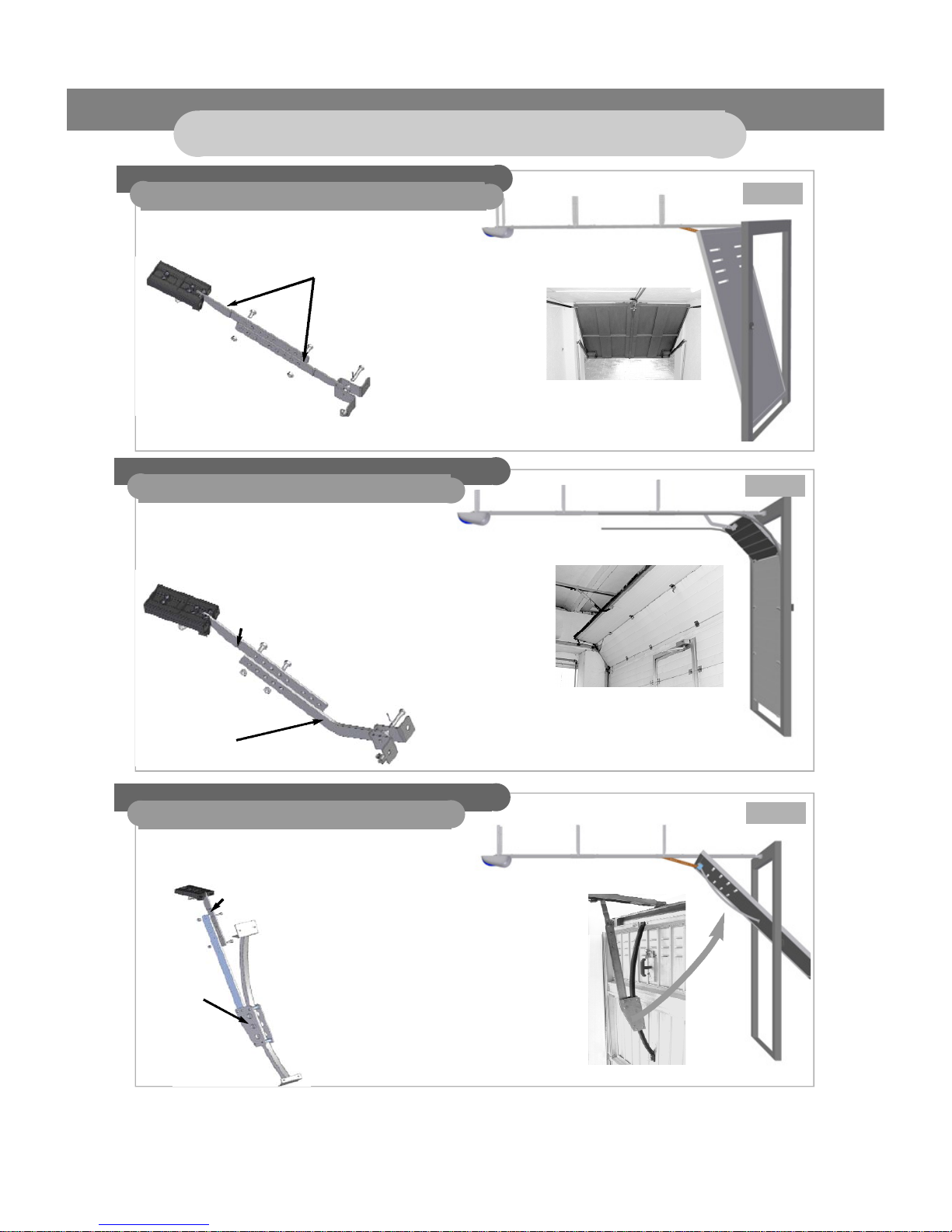
3. Garage door types
3.1 Non projecting up-and-over door
3.2 Sectional door
3.3 Projecting up-and-over door
For the installation on a non projecting up-andover door, no extra accessories are needed.
For the installation on a projecting up-and-over
door, extra accessory “canopy arm” item #
992012* is needed.
Canopy arm: item # 992012 must be
purchased separately.
Draw.2
Draw.3
Draw.4
Use the 2 standard door brakets to connect the trolley to
the door.
trolley
standard door
brakets
standard door
braket
sectional door shaft #992014
Use 1 standard door braket +
the sectional door shaft to
connect the trolley to the door.
Use 1 standard door braket +
the canopy arm #992012 to
connect the trolley to the door.
trolley
trolley
CANOPY ARM t
#992012
standard door
braket
For the installation on a sectional door,
1 of the 2 supplied standard brackets must be replaced
by the supplied sectional door shaft #992014
Page 7

Page 7
4. Operating limits & Installation scheme
Photo beams 1 couple (optional)*
Motor with electronic board inside
Unlocking system from outside
(must be connected to a handle)
Rack containing the chain drive system
Power 230V - 50/60Hz
*Photo beams are not included in the kit, but can be purchased separately as optional safety device
ceiling
rail
To fix the rail of the garage door opener, a minimal distance of 5 cm is needed between ceiling and door.
And a minimal distance of 1cm is needed between rail and door ( see draw.6)
Draw.5
Draw.6
rail=3 cm
Min. 1 cm
Counterweighted /
projecting up and over door*
*= need extra accessory
canopy arm part#992012
not included in the kit
Standard door
max.
h 2,15 m
Sectional door
max.
h 2,15 m
max.
h 2,30 m
MAX traction
force = 100 Kg
Page 8

Page 8
Installation scheme
Wall mount
(this zone must be strong and
reinforced with an iron plate if
needed)
Draw.7
Page 9

Page 9
extra support for rail
the rail pieces “830” can be additionally fixed to the ceiling with a cable
Gear support The gear box must
be fixed to the ceiling with the supplied parts “821”
CAUTION:
to prevent injury from pinching, keep hands
and fingers away from the joints while
assembling the rail.
to avoid serious injury to fingers from
moving garage door opener:
always keep hand clear of spocket while
operating opener.
Securely attach spocket before operating
Door mount
(this zone must be strong and
reinforced with an iron plate if
needed)
!
Page 10

Page 10
5. Assembly instructions
1° step: “U” Rail assembly
2° step: fixing the belt into the trolley and around the pulley
Assemble the 3 elements of the rail (part # 829) by fitting them into the 2 rail braces (part # 830).
See draw.8-10.
The pulley and the trolley are supplyed pre-assembled:
Draw.11
Draw.8
Draw.9
Draw.10
pulley
Trolley
wall mount
fixing plate
belt tightener
Belt securing plate
Page 11

Page 11
Draw.15
3° step: sliding the trolley with belt and pulley into the “U” rail
Slide the belt through the trolley as showned on draw.12 and then pass it around the pulley.
Lock the belt with the securing plate as showed on draw.13-14
WARNING: The securing plate must connect the belt in a specific position: on the side opposite to the
unlocking plug fixed on the trolley, and between the trolley and the pulley. The notch must face
inside.(draw.12)
Draw.12
Draw.14
Draw.13
Pulley
Belt
“U” rail
trolley
Belt securing plate
notch
facing inside
Slide the assembled belt, trolley and pulley into the assembled “U” rail .
Draw.16
Page 12

Page 12
turn the motor head, and take off the pulley cover. Slide the belt around the pulley ( draw.17).
Put the pulley cover on and fix it with the screws ( draw.18).
Insert the “U” rail into the plate through the guides until it stops ( draw.19-20)
NOW your garage door opener is full mounted and ready to be fixed to the door
Draw.19
Draw.18
Draw.20
Draw.21
rail
guides
guides
pulley
pulley cover
screw
4° step: connect the belt to the pulley on the motor plate
Draw.17
Draw.17.a
screw
screw
pulley cover
Page 13

Page 13
Hang the motor head.
The hanging brackets must be attached to the motor plate and angled at 90° at the ends, as is showed
in draw 25-27. Then fasten the brackets to the ceiling.
The rail can be fastened to the ceiling through the holes in the rail braces, in order to prevent the rail
from warping. This is a useful solution expecially when utilising accessory 992012 (up-and-over doors).
6° step: Motor Head Mount:
Draw.24
Position the pilot holes horizontally on the vertical centre line of the door.
Fasten the bracket 828 to the door jamb or wall by means of 2 bolts (not supplied) of the right size
and type of the structure.
Take and hold the opener to a horizontal position, until it can be attached to the ceiling. (draw.24).
Warning: the fastening area must be reinforced and structurally resistant.
5° step: Door Jamb Mount:
6. Fixing instructions
Draw.22
Draw.23
Draw.25
Draw.26
Draw.27
Bracket
828
belt tightener
Bolt
rail
Page 14

Page 14
Close the garage door.
The fixing plate 809 is supplyed pre-assembled to the trolley by 2 brakets. These brackets are supplied
for installation on a STANDARD NON PROJECTING-UP-AND-OVER DOOR
1°) Push left the unloking handle to release and manually moove the trolley ( draw.28)
2°) Slide the trolley to the front and advance the brackets to find the right fixing position of the plate 809.
3°) If necessary, adjust the leght of the brackets, by sliding them one on another and fix the appropriates holes.
4° )Fasten the plate 809 to the door by means of 2 bolts (not supplied) of the right size and type accordingly to your door. (draw.30)
Warning: the fastening area must be reinforced and structurally resistant.
7° step: Door fixing
Draw.30
door fixing
plate 809
standard door
brakets
door fixing
plate 809
Draw.32/A
WARNING : for installation on a sectional door,
For the installation on a sectional door, 1 of the 2 supplied standard brackets must be replaced by the
supplied sectional door shaft #992014 as in draw. 32/A
( see also page 6 point 3.2)
Draw29
Draw31
Draw28
unlocking handle
slide the trolley to the front
standard
door braket
sectional door shaft #992014
Use 1 standard door braket +
the sectional door shaft to
connect the trolley to the door.
trolley
Page 15

Page 15
An unlocking system is provided to unlock the trolley and move the door manually. Composed by an iron
wrap with his sheath, it must be connected to the unlocking undle positioned on the trolley.
Pass the iron wrap inside the hole of the handle and slide it into the sheath (Draw.34) then pass the iron
wrap and sheath into the door fixing plate (Draw.36)
Fix the iron wrap on the handle of your door using the supplied wrap-compressor (Draw.37-38).
To unlock the gate from inside or utside rotate the door handle anti-clockwise (Draw.38).
To lock the trolley, moove manually the door until the belt securing plate fits again in the trolley ( it will
happen automatically while mooving the door.
WARNING: to control the door with your radio remote control, the trolley must be locked!
7. Manual release system
Once the opener has been
installed, tighten the belt by
means of the belt tightener as is
showed in draw.33 so that the
belt does not swing excessively
during movement. Do not over
tighten the belt.
8° step: belt tightener
Draw.33
turn the nut to tight the belt
WARNING:
for installation on a
projecting up-and-over door,
an extra canopy arm (not supplied inside the kit) is
needed to connect the trolley to the door) as in draw.
32/B.
Please see also page 6 point 3.3.
.
Please refear to the specific intruction manuals supplied with the canopy arm to be separately purchased.
door
fixing
plate
iron wrap
sheath
Draw.36
Draw.35
iron
wrap
sheath
Draw.34
trolley
CANOPY ARM
# 992012
standard door braket
Draw.32/ B
Page 16

Page 16
8. 230V power supply wiring
Draw40
Draw.41
Draw.42
230V
Protection FUSE
5x 20 mm 1AT fast
230V
transformer
motor
cover
Draw.39
High voltage 230V
cable compressor
Draw.43
!
Draw.37
wrap compressor
811
822
Draw.38
door
handle
Wrap connection to manually unlock from inside and outside the door.
Connect the cable to the handle.Turn the handle to unlock.
Lift the motor cover (draw.39-40)
Connect the 230 V 50/60 Hz input cable to the transformer terminal board (draw.41-42-43).
A fuse is mounted on the transformer to protect low voltage system (draw.42).
We recommand to use a cable compressor ( not supplied) to fix the cable when passing it trough the
motor plate (draw.43)
Remember to veryfy the protector fuse is not broken, and in case, replace it by a new one.
When the operation is completed, close the cover.
CAUTION:
high voltage supply must be connected by a certified
installer only ! operations with 230V power are very dangerous
.
Risk of serious injury or death !
Page 17

Rolling code remote ref. 6203/ rolling transmitts a unique “rolling code” (billions of continuously changing
combinations) on a frequency of 433 MHz. With 2 buttons, has 2 channels of transmission.
1° channel = pushing on “ON “ button
2° channel = pushing on “OFF “ button
To operate your garage door you must memorize the remote control code on the electronic board.
WARNING:Operate adjustments and settings only with garage door in closed
position.
To memorize the remote control code inside the electronic pnel of the opener:
The door must be closed and idle.
- Press button P1 on the electronic board. The red LED is on.
- Release button P1 and immediately press on the buttons of the remote control that you wish to
use to operate the opener. Hold the remote button pressed for about 4 sec.
- the red LED on the electronic board will quickly blink
then it stays switched on for about 6 secondas before tol switch off.
- Press again the memorized remote control button, the opener will start an operation.
Max. 10 remote control codes can be stored by each electronic board of the gate opener.
To erase the codes from the control board:
To deactivate any unwanted remote, first erase its memory from the electronic board of your garage
opener as following (all remote control codes memorized will be delated):
- The door must be closed and idle.
- Press button P1 for about 20 sec. until the red LED blinks.
- Then release P1.
- All remote control codes have been delated.- Reprogram each remote you wish to use.
Maintenance: To change the battery unscrew the screw on the back of the remote and open the covers.
Use a Battery 12V type A23-5mA.
Page 17
9. Remote control coding (6203 rolling code)
10. Power adjustment
The force can be ajusted by turning the Force setting trimmer “POWER”.
It regulates the amount of power required to open and close the door.
Set the right power properly according to your door weight and frictions.
Push on your remote control to operate the door in the down and in the up position to check if power is
set properly.
Turn RV1 anticlockwise to improove power.
Turn RV1 clockwise to reduce power.
WARNING:
If power is set at a too low level,
the door will stop before reaching the open or closed position.
Draw44
POWER
“ON”
button
“OFF”button
-
+
Draw.45
red LED
P1
Page 18

Page 18
11. Electronic Board CTH29S
P1= push button to memorize or dela-
te remote controls code
LED= red light LED as indications for
memorizing or delating remote control
codes
POWER=
force setting trimmer:turn
anticlockwise to improve power.Turn
clockwise to reduce power.
TIME= trimmer to set the automatic
closing timer adjustment 0-100
sec.Turn fully clockwise to set the step
by step function.Turn anticlockwise to
setautomatic closing function to a
max.pause time of 100 sec
1=
ANTENNA CABLE
2 =
GROUND Antenna
3/5=
START
4/5 =
Photo beam contact
6= PHOTO BEAM POSITIVE
7 =
PHOTO BEAM NEGATIVE
7/8 =
blinking light 24V 10W max
9/10 =
extra courtesy light
13/14 =
limit switch connector
15(+) =
motor blue cable connection
16(-) = motor red cable connection
From tranformer:
V0
black(=0V);
V2
red(=24V);
V1
yellow (=12V)
halogen lamp
20V 24W
P1
LED
POWER
-
+
0
100
sec.
TIME
START
Photo beam
transmitter
key switch
External
antenna
+
-
-
+
C
FTC
Garden courtesy light
24V 10W max.
Photo beam
receiv er
Blinker
WARNING:
if no photo beam connected the
bridge between outlets 4 and 5
must remain connected.
!
!
To transformer
To travel limits
To motor
Draw.46
Page 19

Page
Draw.47
Draw.48
Trolley : when the
door is open shuttle
is in back position
Trolley : when the
door is closed
shuttle is in front
position
DOOR CLOSED:
when the door is in
the closed position, red
flag must touch the
limit switch
DOOR OPEN:
when the door is in
the desired open
position, green flag
must touch the limit
switch.
12. Setting the travel limits
Limit
switch
Red Flag
Limit
switch
Green Flag
Warning: to operate setting of travel limits you must check that:
the electronic panel must be on step-by step operating function =
“TIME” Trimmer must be completely rotated clockwise. See page 20;
Travel limits regulates the points at which the door will stop each operation when moving up or down.
The 2 limits flags red and green will stop the door movement when they get in correspondance of thellimit switch .
Red Flag = closed door
Green Flag = open door
1) your door closed: Position the red flag in correspondance of the limit switch ( draw.47)
2) your door open: Position the green flag in correspondance of the limit switch ( draw.48)
To set the travel limits:
- Unlock the trolley ( see page 15).
- manually close your door.
- With the door in closed position unscrew a little bit the red flag, moove it and position it
in correspondance to the limit switch ( the limit switch must be pressed by the red flag).
- push on your remote control to activate the opener.It will automatically re-lock the trolley while mooving.
- While the door starts to open, unscrew a little bit the green flag, moove it and when the door is in the
desired open position, tightly screw the green flag in correspondance to the limit switch ( the limit switch
must be pressed by thegreen flag).
Page 20

Operate adjustments and settings only with garage door in closed position, and
make sure any object child or person will be in the operating zone
To activate the door automatic closing programme, rotate the “TIME” trimmer anti-clockwise from 0 position, until the desired time pause interval is reached. The adjustment range is 0-100 sec. Your door will
automatically close after the programmed temporized pause.
Position= 0 (trimmer completely rotated clockwise) will activate the step-by-step function = opens - stop closes.
The garage opener setted in automatic closing functio will not accept remote control/ keypad or key
switch impulse while in pause time.
WARNING:
If you set the automatic close operating function, the risk of
injury of people or damage to objects increases !
In order to prevent injuries: never leave or permit to leave any object or
car in the operating zone of your door mooving zone. Neve leave chidrens without parental contol or adults nearby the door if you set the automatic closing function.Allducks recomends to use step by step function.
Page 20
Courtesy light:
The courtesy light on the electronic board can be replaced with the following model:
Halogen lamp 20V 24W
Remote control batteries:
The duration of remote control batteries is approx. 2 years.
Batteries can be replaced with the following model:
12V type A23 - 5mA
Protection fuse:
In the event of short circuit, the protection fuse can be replaced with the following type:
Fuse 5x20mm 1A T fast ( see on draw.40, page 14)
1) Opener does not operate:
- check electric power supply.
- check the protection fuse and, should it be necessary, replace it
- check motor function by triggering it through the start contact (see drawing)
- check that the remote control code is stored in the opener board (erase all memories first and then
store the code)
- The batteries could be discharged. Replace them.
2) The opener opens but does not close:
- If the photo beams are not connected, check that the bridge between outlets 4 and 5 is appropriately
connected.
- if photo beams are connected, check their alignment and that they are clean both inside and outside
- also check that no automatic closing function has been programmed. Should this be the case, the
system will not accept closing commands.
3) The system does not operate from remote beyond a certain range
- there may be interferences in the air. The use of an external aerial antenna is recommended.
4) The door does not close in the desired position
- check that there is no excessive friction at a specific door position
- check the power level, and eventually increase it
- check limit switch settings
0
sec.
=step by step
100
sec.
TIME
13. Automatic closing
14. Maintenance
15. Quick Help to Problem solving
Draw.49
!
Page 21

Page 21
DUCATI products are guaranteed for 24 months from purchase date, for manufacture or material defects. In case of repair, the
product shall be returned to the to one of our authorised after-sale centres. The authorised technical assistance centres are the
only acknowledged suitable to carry out repairs under guarantee. In case of difficulties, or to get the after sale offices of your
country please address to:DHA Srl Via Cassani snc 1 - 43036 Fidenza (PR) ITA LY Tel. +39/0524/527967
mob.+39/335/1022019 info@ducatihome.it www. ducatihome . i t
Guarantee conditions
1.The guarantee is accepted only the demands presented with the invoice or coupon proving the purchase; no alteration or cancellation shall be on the certificate.
2.DUCATI obligations are limited to the repair or, at its own discretion, to the defective parts replacement.
3.The product guarantee shall immediately decay if the product is modified and adapted to technical and safety norms diff e r e n t
from the ones in force in the country the product was conceived and manufactured for.
No refund is foreseen for damages deriving from the above-mentioned modifications.
4.The guarantee does not cover:
a) Periodical checks, maintenance, repairs or replacement of worn out parts.
b) Transport, handling or installation costs relating to this product.
c) Improper use, mistakes in the operation and incorrect installation.
d) Damages caused by fire, water, natural phenomena, storms, incorrect power supply, or any other cause not depending on the
m a n u f a c t u r e r.
5.This guarantee neither influence the rights of the customers envisaged by law, according to the national applicable laws, nor
the rights of the customer towards the reseller deriving from the purchase contract.
In case there were no national applicable laws, t
his guarantee shall be the only safeguard for the customer and neither the
manufacturer nor his distributor will be responsible for accidental or indirect damage to their own products deriving from the
infringement guarantee conditions.
16.Warranty & After sale service
830
830
829
829
2 x 821
992014
835
CTH29S
810
811
832
828
834
809
831
2 x812
829
RAIL SET contents:
FIXING SET contents:
BELT SET contents:
transformer 230V
belt pulley
8900T/ belt/ roll
Complete garage
motor head with electronic panel, motor
and transformer
compleete motor
825/R117
R403 UE
826
17. Spare parts
SW5000
SW6500
SW7950
6025/5
SW7012
SW7500
Remote control
key switch
radio key pad
wide angle
mirror
external antenna
with 5 m cable
Blinker
photo beam
6203 rolling
992012
Canopy arm
18. Extra Optional accessories
How to order spare parts or optional accessories:
shop online : www.ducatihome.it
Page 22

Page 22
19. CE declaration
DECLARATION OF CONFORMITY
WE
DUCATI HOME AUTOMATION
Automazione Cancelli Via Cassani, snc
43036 Fidenza (PR) ITALY
declare under our sole responsabilità that the products listed below to witch this declaration relates:
UP100
Garage Door Opener
when installed, used and mantained according to all the manufacturer instructions on a garage door
witch have also been installed correctly accordino to all security and safety norms indicated by the
Manufacturer, , are in conformity to the applicables sections of standards:
EMC: EN61000-6-2,EN61000-6-3,EN301489-3,
EMF: EN50366,EN50371
SAFETY: EN60335-1 4° ed.., EN60335-1:2002, EN60335-2-103:200ì3
En60335-2-103,
EN60529;
EN60950-1;EN60947-5-1, EN60598-2-1
ETS300683 ,
EN55014-1, EN55014-2:2001
EN60555,
EN13241,
EN 6100-3-2; EN6100-3-3
EN12453:2000
EN12445
Following the provisions of EU Directivesand all ammendments:
89/392/EEC, 99/05/CE ,73/23/CEE,89/336/EEC, ENC300 220-3
and all its amendments.
Remote control 6203 rolling,
Certificate n°: CE 0681
FCC ID OLS137925764
The mentioned items are in compliance with RoHS rules
 Loading...