

Page 1
8
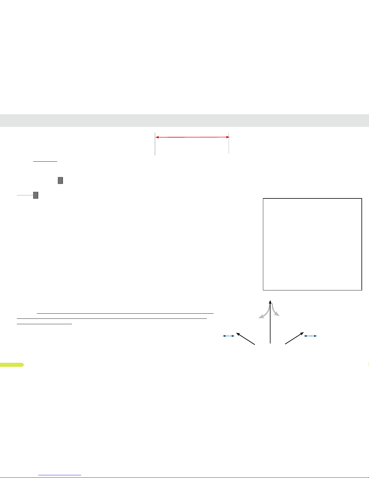
DUCATI General installation diagram
L
1
3
4
8
7
6
5
2
2
9
9
9
9
It is mandatory that your gate has mechanical limits xed on the ground.
The limits must stop the gate wings in the closed and open position of each wing. Your gate must be
provided with mechanical end stops to be automated. The end sops on the oor can only be omissed
in case of gate opener supplied with integrated limits (FC versions).
Ducati’s gate openers are conceived to stop by amperometric detection. When the gate wing touches
and pushes on the mechanical limit (end stop), an amperometrical increase is detected by the control
board and motor stops. An imperceptible drive reversal draws pressure from the gears of the engine
to preserve its life
Warning: make sure not to use the full actuator stroke as the gate wing must stop by pressing
on a mechanical end limit (fixed on the ground or FC onboard limit) before the actuator rea-
ches the end of it’s stroke.
Warning: if you purchased an FC version actuator, check whether the integrated limit can be used for
the open or closed gate position: in fact, not all FC-actuators have double end travel for both positions
gate open + gate closed. The use of the integrated travel limit also depends on the opening direction
of the gate ( push-to-open or pull-to-open).
Example of End
stop limit to be
xed on the
ground
1°
2°= M2
15 cm
min.
15 cm
min.
Mechanical end stops
(limit) to be fixed on the
ground
1°= M1
(Gate that
opens first)
Mechanical end stops (limits)
1= Control box with containing electronic
board with on board radio receiver,
toroidal transformer, integrated battery
housing compartment.
2 = actuators
3 = blinking light
4 = external antenna (if supplied)
5 = key switch
6 = radio remote control
7 = radio keypad (if supplied)
8 = solar panel (if supplied)
9 = pair of photocells (if supplied)
L= wing lenght
POST
GATE
Actuator
To ensure a perfect lock of the gate when
closed, the actuator must be installed in way
to have an angle of incidence to the gate
wing in closed position.a greater angle ensures greater tightness
Angle
WARNING: angle of incidence
A
B
A= junction box
B= safety power switch
Page 2
9
H
V
K
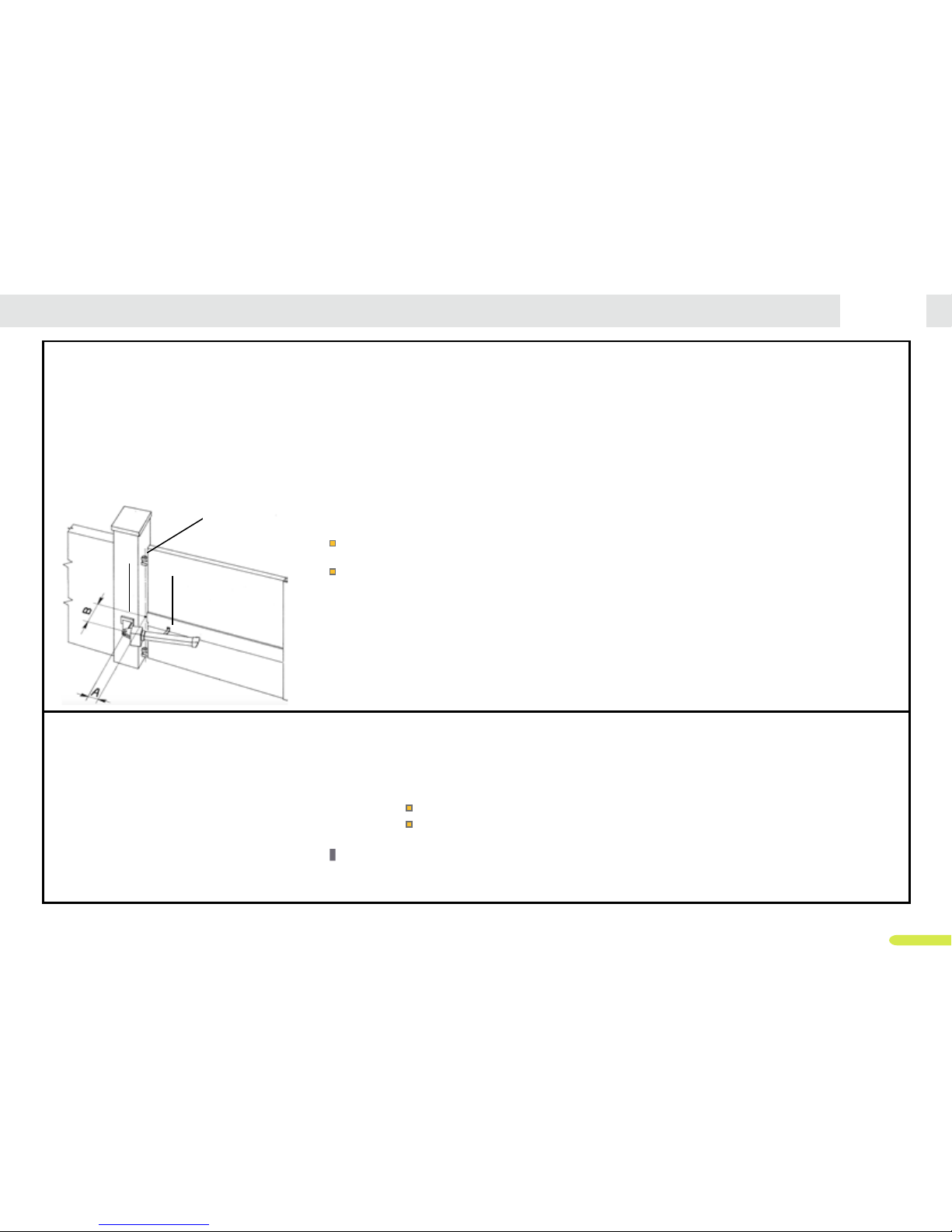
Pillar dimension:
How this inuences your gate opener system. Determinate the ideal A & B measure
A= distance between the hinges of the gate and the actuator’s post xing pin. This distance can be chosen by the user.
It is recommended to use a measure similar to the “B” measure.
B= is te most relevant measure and determinates gate opening speed and max. opening angle. it’s determinated by the pillar
dimension + xing bracket.
Shorter B measure determinates faster opening of your gate.
If you require major opening angle choose a short B measure and longer A measure
V= gate hinges
K = post xing bracket
H = front xing bracket
Longer telescopic actuators, allow better mechanical operation given by the greater strength of the lever.
Carefully evaluate the size of the pillars in relation to the tables that you will nd in the pages that present the limits of use and
DUCATI General installation diagram: mechanical limits & pillar dimension
PULL TO OPEN OPERATION (gate that opens towards inside)
This means the gate operator is mounted on the inside of the property and pulls your gate in towards the property to open.
Warning: Each actuator model has limits to the use of measurements A and B. Therefore, verify the conformance of the actuator model with the size of your structure (see
following pages the measurement limits A and B for each actuator model). The greater the distance between the gate hinge and the inner edge of the pillar, the longer the
chosen actuator will be. It is recommended to install actuators with a certain incidence angle over the gate (not too parallel to the gate itself) for better mechanical perfor-
mance.
A and B measure the distance between the gate hinge and the rotation center of the actuator (respectively on longitudinal axis and transversal axis). These measurements
determine the maximum opening gate and opening speed of the gate. Check the A & B limits for each actuator model in the following pages.
CAUTION: It is recommanded not to use the entire stroke of the drive and to install actuators with a certain incidence angle over the gate.
CAUTION.:The gate opening speed depends on the length of the actuator’s run used. The less run (stroke) you use, the faster the gate will open.
PUSH TO OPEN OPERATION (opens towards outside)
The gate opener is mounted on the inside of the property and pushes your gate out away from the property. PUSH-TO-OPEN.
Check the overall dimensions before installation.
It is recommanded not to use the entire stroke of the drive and to install actuators with a certain incidence angle over the gate
Warning: use of telescopic actuators is recommended.
Warning: remember to reverse the polarity of the motor cables when connecting to the electronic board
outside
inside
Rear pivot point of gate opener
In line with center hinge
A= this measure must allow the actuator can open the gate wing at 90 °.
B= This measure allows the actuator mounting. Compare it to the actuator dimension
Longer telescopic actuators, allow better mechanical operation. Make sure that the gate do not open onto
a public passageway. It is advisable to prepare a plant with safety photocells to be placed in such a way
that the doors, opening towards the outside do not create damages to things and people who are on the
outside of the property, such as parked vehicles.
Page 3
17
DUCATI SW400 actuator’s installation diagram
SW400
SW400 FC (with on board open & closed
position mechanical limits)
each model is also available in 24V version
PUSH TO OPEN OPERATION (opens towards outside)
If your driveway slopes up after the gate, preventing it from swinging in. This means the gate operator is mounted on the inside
of the property and pushes your gate out away from the property.
Warning: only compatible with telescopic tube actuators, Check
the overall dimensions before installation.
Warning:remember to reverse the polarity of the motor cables
when connecting to the electronic board
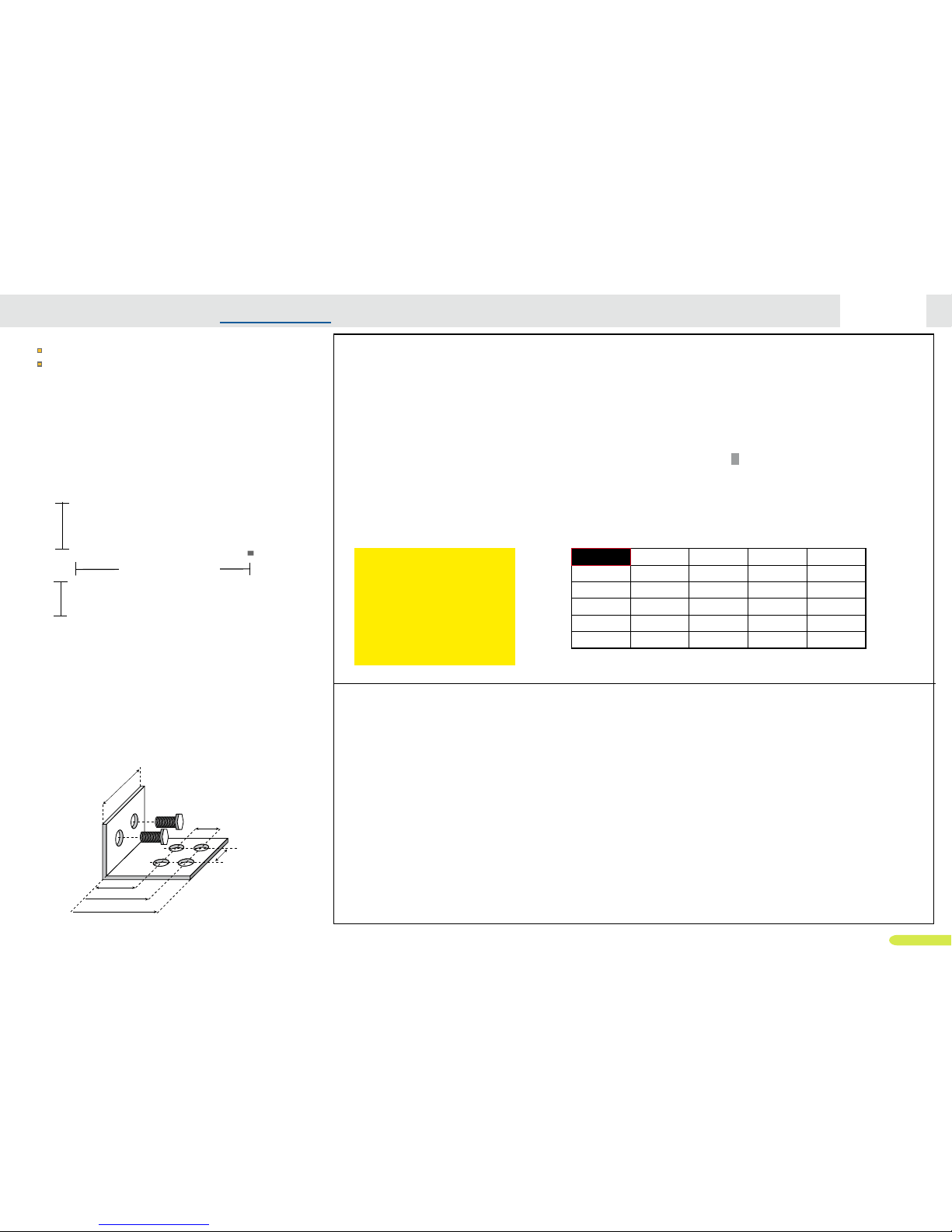
TAB A=10 cm A=12cm A=14 cm A=18 cm
B= 10cm 108° 115° 120° 100°
B= 12cm 105° 112° 100° 100°
B= 14cm 103° 109° 98° /
B= 16cm 101° 97° 90° /
B= 18cm 97° / / /
D = 6cm
D = 8,5cm
D = 10cm
D = 2,5cm
D = 2,5cm
D = 5,4cm
Supplied xing braket:
choose the hole most suitable to your gate.
You can cut the plate if necessary
Maximal wing dimension:
Maximal wing lenght: up to 2m/ 6,5 ft
Maximal wing weight: up to 200kg/ 440lb
NOT POSSIBLE WITH THIS ACTUATOR MODEL: IT REQUIRES TELESCOPIC ACTUATORS
METRIC CONVERSION
1 cm = 1⁄2” = 0,3
”
10 cm = 4”
12 cm = 4
3⁄4
”
= 4,7
”
14 cm = 5
1⁄2”
= 5,5“
16 cm = 6
1⁄5”
= 6,2
”
18 cm = 7”
PULL TO OPEN OPERATION ( opens towards inside)
This means the gate operator is mounted on the inside of the property
and pulls your gate in towards the property to open.
OUTSIDE
INSIDE
Rear pivot point of gate opener
In line with center hinge
175 mm - 530mm
100
mm
140
mm
Page 4
25
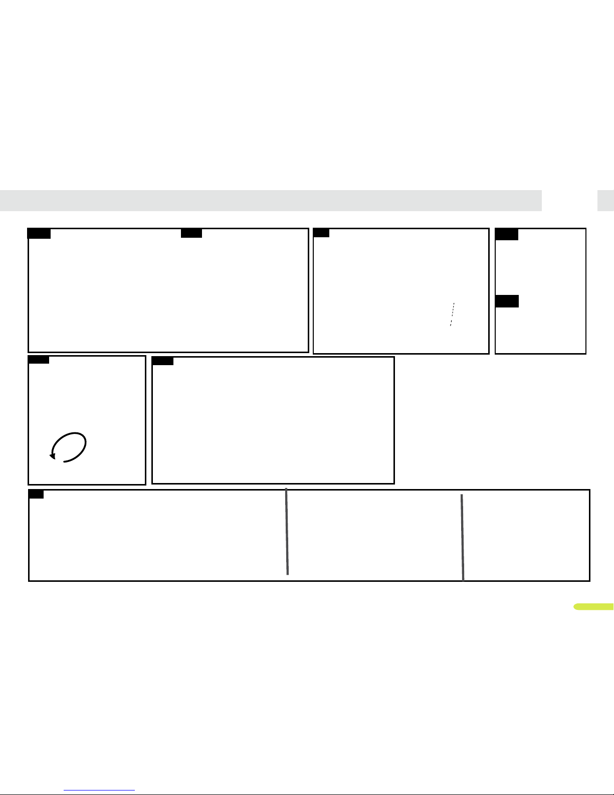
DUCATI SW / EVO actuators: Specic drawings
23A 23B 25A24
26A
27
STANDARD manual release
Mechanical limits (only available on
“FC”versions)
26B
25B
EVO LOCK: optional manual release protection by key
LIMIT POINT
LIMIT POINT
Page 5
26
1. GENERAL CARACTERISTICS and PRELIMINARY WARNINGS
The products described in this manual are intended to be used to automate hinged
swing gates for residential/ commercial or industrial use, within the limits of use and
size provided for each model.
Incorrect installation can cause serious injuries. Before installing the automation
you need to carefully read all the parts of the manual. If in doubt, stop
installation and request clarification from the DUCATI HOME Assistance Service.
WARNING! the gate opener is just one of the components that once installed on
the gate forms the automatic gate machine.
Make sure that the structure, that consists of pillars/ wall/ posts, hinges and gate,
in perfect condition, perfectly installed, solid and robust. Check that the structure
is compatible with the size of the automation and with the limits of use for the
selected gate oepener. Pay attention to correctly install each component of the
gate opener.
A gate opener can not correct defects or structural problems of the gate or
other component of the structure. If the installation is not carried out correctly, it
is not possible to guarantee the proper functioning of the automatic gate system,
neither respect of safety norms.
We recommend tinstallation anti-fall cables to prevent accidents caused by the
phisical fall of the gate.
The structure on which you are installing must be constructed in a
workmanlike manner in accordance with local regulations and satisfy all safety
requirements. The automation can not correct defects in the structure. Check that
the gate leaves are perfectly balanced, that the hinges are in perfect condition
and that the facility is fully operational and complies with safety regulations. Gates
with structural problems should not be automated Warning: Ducati actuators are
designed to be installed to be used indifferently on the right or left leaf of the gate.
WARNING! Any use other than those described in this manual is to be considered
improper and prohibited!
Ducati’s electromechanical actuators are provided with DC motor, worm screw
gear. The motor must be run by a compatible original “DUCATI HOME automation”
control unit only.
The actuator stops its movement by means of an amperometric detection system
as the gate wing reach a mechanical end stop fixed on the ground to set the
open and closed position limit of each wing (only special FC version actuators are
provided with on board mechanical end limit).
In case of obstacle detection, safety is also ensured by the amperometric detection
system in compliance with EN laws.
In case of power failure (black-out), the actuators are provided with a manual
release system by trilobic key.
Warning: to operate the manual release system is required to operate on the
actuator witch is installed inside the property, it is therefore advisable to provide an
indipendent pedestrian entrance.
Pages 4-5: The table shows the compositions of each kit, including the
corresponding actuator model and control board model.
Page 6: the table shows the technical characteristics and application limits of each
actuator model.
Page 7: the table shows the characteristics and comparison of each Control Box
(electronic board).
Page 8-9: shows the general installation diagram as well as important information
about the requirements of the structure
Pages 10-22 shows each single actuator model installation diagram, limits and
overall dimension.
IMPORTANT: Before proceeding with installation carefully read the following
preliminary warnings
2. SAFETY WARNINGS
Warning ! READ AND FOLLOW ALL INSTRUCTIONS contained in this
installation and use manual. DUCATI gate openers have been designed and tested
to offer safe service at condition they are correctly installed, operated, maintained
and tested in strict accordance with the instructions and warnings contained in
this manual. Failure to meet the requirements stated in this instruction manual
could cause severe injury and/or death, for which the manufacturer cannot be held
responsible.
SAVE THIS INSTRUCTION MANUAL
Make sure everyone who’s using or will be using the gate door opening system is
aware of the dangers associated with this system. In case you will sell the property
with the gate opener, Provided for copy of this manual to the new owner.
WARNINGS:
DUCATI
Preliminary safety warnings and important informations DUCATI Preliminary safety warnings and important informations
Page 6

27
• Before starting the installation, check whether the product is suitable to automate
your gate, If it is not suitable, DO NOT proceed with the installation.
Before installation:
Understand your new gate opener
- Read this instruction manual in advance to thoroughly understand its function and
features.
- Verify that this gate opening system is proper for the type, size and weight of your
gate.
- Check the state of your gate & pillars/ posts :
- Make sure that your gate has been properly installed and is functional.
- make sure the gate and post must be suitable for being automated.
- Check that the structure issufficiently strong and rigid, and its dimensions and
weights conform to the limits of the purchased gate opener.
- Make sure the leaves move smoothly without any irregular friction during entire
travel.
- Make sure your gate is properly balanced and lubricated. An unbalanced gate
could cause serious injury or death! Make sure the gate is plumb and level.
-The post must be secured in the ground with concrete. This will prevent alteration
of alignments and leveling during installation and during cycles
- If the gate binds, sticks or is out of balance, before proceeding with gate opener
installatio, call a trained, certified gate technician to correct it and prevent serious
injury or death.
- Repair or replace all worn or damaged gate components prior to installation. Call
a trained professional gate technician for this.
- Make sure the hinges are in good condition. Ball bearing hinges are ideal for
gates wings.
- To prevent damage to the gate and opening system, always disable the manual
locks before installing and operating the opening system.
Prevent serious injury or death by electric power:
- Be sure the power is not connected BEFORE installing the gate opener control
box
- NEVER connect the gate opener to the power source until instructed to do so.
- The gateopener installation and wiring MUST be in compliance with all local
electrical and building codes
During installation
Ensure your personal safety:
- Never wear watches, rings or loose clothing while installing or servicing the
opening system.They could get caught in the gate opener mechanisms.
- High voltage wiring (110V-230V power) must be done exclusively by a competent
professional and certified electrician.
Prevent serious injury or death:
- Be careful when manipulating with moving parts and avoid close proximity to
areas where fingers or hands could be pinched.
- Use concrete anchors when installing any brackets into masonry.
- Do not activate your gate opening system unless you are sure that the area of its
travel is clear of persons, pets or other obstructions.
Watch the gate through its entire movement. Never leave childrens without parental
control in proximity of a gate opener in motion, opened, closed or stopped.
- Never permit children to play with remote control push buttons or transmitters
of gate opener and prevent childrens to operate the gate opener by control push
buttons or transmitters.
- Always keep remote controls out of reach of children.
- Install the electronic box of your opener out of reach of children and away of
moving parts of the gate.
- Activate the gate opener only when the gate can be seen clearly, is properly
adjusted and there are no obstructions to gate travel.
- Always keep gate in sight until completely closed.
Prevent damage of the opening system and reduction of its safety features:
- The motor fixing brackets must be rigidly fastened to the pillar/wall/post and to a
well reinforced part of the gate.
- Never increase force beyond minimum amount required to close the gate.
- Never use force adjustment to compensate for a binding or sticking gate.
After any adjustment is made, the safety system must be tested.
After installation
- Install any fixed control at heigh of at least 1,5m and within sight of the gate but
away from mooving parts
- Make sur you have a second pedestrian access to your property.
Remember: in case of power failure or any problem with your opener you might be
unable to operate it from outside your property
- Save the unlocking key in a safe place out of reach of childrens, in order to
permit to manually unlock (from inside) the gate and operate it manually in case of
power failure or other problem.
Verify correct installation:
- Ensure that the parts of the door do not extend over public foothpath or roads
- Upon completion of installation, unlock the actuators and manually open and
close the gate to check ther’s no mechanical friction and that it works correctly
DUCATI Preliminary safety warnings and important informations
Page 7

28
- Make sure the gate wings stops on mechanical end limit fixed on the floor (not
mandatory for FC actuators where mechanical limit stops is provided on board)
- SAFETY System in compliance with EU norms:
EN 12453 ENSURE SAFETY AND PREVENT ENTRAPMENT- CRUSHING
Any gate or garage door opener is required by the European Union to attent a series
of strict and restrictive mandatory regulations which clearly regulate the automation
industry.
Any new or existing installation requires a declaration of conformity issued by the
manufacturer.
DUCATI not only self-certify his products, but also mandated International Notify
body laboratories to perform full tests to certificate the compliance of the products to
all applicables EN norms.
DUCATI ensure that the forces generated by a correctly installed gate opener, when
touching a person or an obstacle are limited and that they do not exceed the values
specified in Annex A of BS EN 12453:2001.
The final machine to be tested is composed by 2 foundamental elements: the
structure ( gate or garage door) and the automation device. This 2 elements
compose the machine: automated electric gate/ automated electric gate system.
Any new or existing installation requires a declaration of conformity issued by the
final installer. The installer must test the final machine and attest the compliance
to the latest European standards concerning impact forces in case of obstacle
detection. Tests must be performed with a dinamoteter in precisely specified
positions
Ensure safety and prevent injuries:
- Place warning sign of automated gate on the gate or nextto it. Permanently fix a
label warning against entrapment in a prominent place or just near any fixed control
- Without a properly working safety system, people (particularly small children) can
be SERIOUSLY INJURED or KILLED by a closing door. After installation ensure that
the mechanism is properly adjusted.
- Never permit anyone to cross the path of a closing gate.
- No one should go close to a stopped, partially open gate.
- Never leave children unsupervised near a gate opener, whether moving, open,
closed or stopped.
- Never permit children to play with the gate opener’s remote control buttons or
transmitters, and do not allow children to use them to operate the gate opener.
Always keep remote controls out of reach of children.
- Install wall-mounted gate controls out of the reach of children and away from
moving parts of the gate.
- Always keep the gate in sight until completely closed.
- While the gate is closing, do not attempt to stop it by hand. This is extremely
dangerous.
MOUNTING HARDWARE:
To compleete the installation you need at least following material:
plastic hammer;
pinching for Seeger;
level;
frame fixing;
Cross screwdriver PH2;
flat screwdriver 2,5 mm;
adjustable wrench;
outdoor electric cable ( 2 poles) H07NRF length according to the connection of the
two actuators to the control box;
4 bolts for fixing plates with the gate with a diameter 8 mm length according to the
thickness of the-gate;
4 bolts for fixing plates with the pillar with a diameter 8 mm length according to the
thickness of the pillar; pinching;
vice;
cable clamp.
Outdoor electric cables for additional accessories connections (0,5mmq)
Prepare all the tools and material of use necessary to the installation.
Tools must be in perfect state and in conformity with the safety rules indicated by
the national law.
Prepare and install an insulated underground ICT25 mm shealth to pass the
actuator cable (2x1 mmq) to the contol box as well as the photocells cables.
How to install the actuators
3. General installation diagram
The diagram on page 8 shows an example of a typical automatic system.
Referring to this diagram, determine the approximate location where you will install
each component envisaged in the system and the most appropriate connection
diagram.
The actuators should preferably be installed at a height between the two gate hinges,
and always in line with a reinforced horizontal cross of the gate to fix them in a
structurally strong point. In case the gate is not provided wit a reinforces horizontal
cross, the gate structure must be reinforced at the actuator fixing point
The actuator should anyway never beeing installed less than 15 cm from the ground
DUCATI
How to install the actuator DUCATI How to install the actuator
Page 8

29
The control unit box must be placed outside the reach of children and unauthorized
persons, (at a suggested high of min. 1,2 m from the ground) preferably with a
minimum distance of 60 cm from the actuators. If the control unit is not installed next
to the gate but remotely, for example in a control room, an external radio receiver
must be added to the system, which receives the radio signal in proximity of the
gate.
The actuators must be connected to the main electronic board by a outdoor use
bipolar electric cable H07NRF min 1 mmq.
The accessories must be connected with an outoor use min. 0.5 mmq electric
cable. (Cables, screws and dowels on the structure are not provided, but must
be purchased separately according to the system and the specific material and
dimension of the structure).
Automatic gate opener essential components
The minimum components needed to automate a swing gate are:
1= Control box with containing electronic board with on board radio receiver, toroidal
transformer, inner battery compartment.
2 = actuators
3 = blinking light
6 = radio remote control
Useful additional componentsto complete the automatic gate system:
4 = external antenna
5 = key switch
7 = radio keypad
8 = solar panel
9 = pair of photocells ( receiver + transmitter) & pair of photocells integrated in
coloumns
+ GSM module and /or GSM Intercom to command your gate opener by your
mobilephone
Gate opening towards inside (pull to open) or outside the property (push to
open)
CAUTION: the most common types of gates are those with opening to the inside
of the property. It is however also possible to automate gates that open out of the
property following the following warnings:
to automate a gates that opens towards inside the property, it is necessary to use
a compatible actuator model (telescopic actuators are recommended). check the
DUCATI How to install the actuator
specific actuator diagram (page10-22) to verify it is compatible for installation on
gate that opens towards outside.
NOTE: in the case of gate opening to the outside ( PUSH-TO-OPEN) , it is
necessary to reverse the polarity of motor cable wiring (check electronic wiring
diagram of your electronic board model (page 36-52)
Check the feasibility of such a system considering the lateral overall dimensions.
Make sure the gate wings do not open on a public passageway (This may be
prohibited by specific national or local law, and you may be held liable for damages
or injuries caused to third-party)
It is advisable to equip the system with a safety light barrier (photocells), which
should be positioned so that the wings do not cause any damage or disturbance to
any passing pedestrians, bikes or parked vehicles.
4. HOW TO INSTALL THE ACTUATOR:
The actuators must be installed inside your property.
First of all you should determine the height at which the actuators will be positioned.
They should be preferably installed at a height between the two hinges, remember
they must always match a reinforced horizontal cross of the gate to ensure the
actuator is installed in a resistant part of the structure of your gate.
Warning: the actuator should never be installed less than 15 cm from the ground
Warning: the actuators must be installed horizontally in line with the gate: Check
with a spirit level that the gate is perfectly balanced and make sure the drive is
in balance with the gate. Take into account that if the actuator is not installed in
line with the gate, it may causea point of majour friction during travel, incorrect
operationand damages.
Identify the exact model of the actuator delivered in your gate opener package kit
(see table page 4-5) and verify that the installation limits and the maximum A and B
measures your stucture must comply to be compatible with your actuatoethat your
actuator
are respected.
4.1 – Post mounting bracket
Pillar/ Coloumn/ fence post: determinate the position where to install the post
mounting bracket
According to the actuator model, and to the pillar/wall dimension, calculate the ideal
fixing position of the rear bracket by consulting the installation schema of your
Page 9
30
DUCATI
How to install the actuator DUCATI How to install the actuator
actuator’s model see diagram on page
HC 312................................page 10
HC 412................................page 11
HC 512................................page 12
HC 612................................page 13
HC 418................................page 14
HC 518................................page 15
HC 618................................page 16
SW 400...............................page 17
SW 400T.............................page 18
EVO 700.............................page 19
EVO 700T...........................page 20
EVE 900.............................page 21
EVE 900 T..........................page 22
VERY IMPORTANT ADVICES:
WARNING: The actuator should preferably have a angle of incidence to the
closed gate and therefore not be perfectly parallel to the gate wing (see page 8).
This will keep your gate well locked when the gate is closed, as the actuator will
push the gate wing to the end stop with major force.
WARNING: make sure not to use the full actuator stroke as the gate wing must
stop by pressing on a mechanical end limit (fixed on the ground or FC integrated
limit) before the actuator reaches the end of it’s own stroke travel (see page 8).
In case of telescopic actuator it allows to keep the telescopic tube more guided
when it is extroflexed, ensuring greater solidity.
WARNING: In Gate opening towards inside the property ( PULL-TO-OPEN)
measures A & B shown in each actuator’s diagram as well on page 9 are extremely
important as they shall determinate the gate opening angle and speed as well
as actuator thrust strenght. The shorter travel of the actuator’s stroke is used, the
greater the gate opening speed will be.
In general, smaller the A and B measurements,will result in higher gate
opening speed.
Attention, it is recommended not to use a too high opening speed to avoid
unwanted bumping rebounds at the end of the maneuver.
Where possible increase measure B to reduce speed.
Important! to allow a linear movement of the automation A & B measures should be
similar.
Warning: on double wing gates use same A & B measure on both sides.
To determine the most suitable mounting position, proceed as follows:
- Measure the depth of the the Post/ pillar column where your gate is installed to
(measure from thecenter hinge to the inner edge of the column)
-After the depth of your post has been measured, compare it to maximal dimensions
A and B indicated in the table of your actuator’s model.
Warning: “B” measure is the sum of the depth of your pillar to cente hinge +
lenght of fixing brackets supplied.
Warning: the supplied post fixing brackets offer several holes choice.
- Select the hole where to fix the actuator to, accordingly to A & B meassures limits.
- If necessary, cut away the excess of the bracket.
Warning: in some cases it will be necessary to get tailor-maid post fixing brackets
made by a blacksmith (for example in the case of round columns).
- Now determine the mounting position of the plate on the column, taking into
account that the dimension B determines the maximum opening angle and the door
opening speed. If this angle does not match your needs, you should re-adjust quote
A and quote B so that they are similar.
Warning: Before securing the rear bracket and keeping the actuator in a perfectly
horizontal and balanced position, perfectly horizontal supporting the engine, verify
that the front fixing point of the actuator coincides with a solid and robust cross of
the gate. Make sure that the actuator is mounted at a minimum height above the
ground ( min.15 cm are recommended) so that it is easy to operate the manual
unlocking system.
Warning: in case your structure dimension do not allow to comply with the A& B
dimensions stated in the actuator table & diagram (ex. large masonry pillar), you will
need to carry out masonry works to allow the correct instalaltion of the gate opener
Fix the bracket to the pillar/ coloumn/ fence post
Each actuator model is provided with specific fixing brackets.
Mark middle of post bracket slots on pillar/ coloumn/ fence post.
Fix the bracket on the pillar. Use suitable fastening bolts anchors (not supplied)
suitable to the pillar construction material (iron post / concreete, bric or stone pillar).
FIx the actuator to the post bracket:
Fasten the actuator to the bracket of the rear fixing with the pin and seal ring
- for EVE actuators see pag..23
- for “HC” actuators see pag.24
- for “SW” & EVO actuators see pag.25
Page 10
31
DUCATI How to install the actuator
4.2 Front mounting bracket: How to determinate the position where to install the
front mounting bracket
Warning: make sure not to use the full actuator stroke (save at least 1-2cm of
travel) as the gate wing must stop by pressing on a mechanical end limit (fixed on
the ground or FC integrated limit) before the actuator reaches the end of it’s own
stroke travel (see page 8).
In case of telescopic actuator this allows to keep the telescopic tube more guided
when it is extroflexed, ensuring greater solidity.
Suggestion: if it is necessary to move the actuator forward or backward, the motor
can be powered directly with a 12V battery: connect the motor’s two-pole cable to
the two poles of the 12V battery. By inverting the polarity the motor reverses the
direction of travel
Warning:
A) TELESCOPIC ACTUATORS,
featuring telescopic stainless steel telescopic tube are supplied with totally
retracted piston tube, therefore the fixing position of the front bracket to the gate
must be determined with the gate in open position* (in case of gate gate
opening towards inside the property)
or Vice versa in the case of a gate that opens outwards (push-to-open).
Resume of telescopic actuators models:
HC312; HC412; HC512; HC612; SW400T; EVO900T; EVE900T (+ corresponding
24V versions)
B) NOT TELESCOPIC ACTUATORS
are provided with running sleigh ( sliding shoe plate) positioned to the front of
the actuator, therefore the fixing position of the front bracket to the gate must be
determined with the gate in closed position* (in case of gate gate opening
towards inside the property)
or Vice versa in the case of a gate that opens outwards (push-to-open).
Resume of NON telescopic actuators models:
HC418; HC518,HC618, SW400; EVO900; EVE900 (+ corresponding 24V versions)
Fix the front bracket to the gate
- The actuator must be fastened to the front fixing bracket, keep it perfectly in line
with the gate wing
- bring the actuator to the gate leaf and identify the fixing point of the front plate to
the wing gate.
- Mark middle of front bracket slots on the gate wing.
- Fix the bracket on the gate. Use bolts anchors or screws suitable for the gate
(wood/ iron/...). It ‘also possible to weld the bracket to the wing of the gate.
- Fasten the actuator to the bracket. Fix it with the pin and seal ring
- for “EVE actuators see page 23
- for telescopic “HC” actuators see page 24 drawing 19A
- for non- telescopic “HC” actuators see page 24 drawing 19B
- for telescopic “SW” and “EVO” actuators see page 25 drawing 25
- for non-telescopic “SW” and “EVO” actuators see page 25 drawing 24a/b
5. MANUAL RELEASE
The actuators are equipped with a release system which allows the manual handling
of the gate in case of emergency.
The release system is operated through the use of three-sided key that must be
inserted into the triangular slot.
Turn of about 180 ° up to the stop in a counterclockwise direction.
The actuators will be unlocked and the gate can be opened manually.
The reverse operation will restore the automatism traction.
Warning! perform the manual release only once the actuator is installed to the gate.
The manual release could be little bit hard in the beginning, but after a run-in period
will be smooth
- for EVE actuators see page 23
- for “HC” actuators see page 24
- for “SW” & EVO actuators see page 25
For “EVE” acuators the optional “ EVE LOCK” manual release key protected
accessory is also available. see page 23 fig. 15B
For “SW & EVO acuators the optional “ SW LOCK” manual release key protected
accessory is also available. see page 25 fig.26B
In order to have access to the release system from the outside, it is advisable to
create a secondary pedestrian passage, especially in the case where the gate does
not allow access from the outside to the system.
Page 11

32
DUCATI DUCATI
How to install the actuator
6. Control maneuver.
Test of correct mechanical installation of the actuators on the gate
After installing the actuators, unlock them and perform some control maneuvers
by manually moving the gate leaves. Make sure that the movement is smooth and
continuous without any point of friction.
7 - MECHANICAL LIMITS
NOTE: the actuator will stop by amperometric detection system: it therefore requires
mechanical stop limits to be installed on the floor to stop the gate wing in the open
and closed position.
It is reminded that, with exhemption in case of use of actuators featured with
integrated mechanical or electrical limits, it is mandatory to install mechanical
gate stop limits to be firmly placed to the ground in correspondance to gate
closed and open position (see page 4).
The gate opener stops running by amperometric detection when the door
detects and presses on the mechanical end limit.
FC actuator versions are equipped with integrated mechanical limits.
for FC actuator versions, where the on-board limit is provided, it is not mandatory to
have gate stops fixed to the ground.
- All actuators of the “EVE” series have a double mechanical end limits for “open”
and “closed” gate position (see page 23 Fig. 16)
- SW, EVO and HC series actuators can be supplied in the special “FC” versions
with integrated mechanical limit/ limits
WARNING:
HC; SW; EVO non telescopic actuators in FC version can be supplied with up to 2
integrated mechanical limit to set both open and closed gate position.
HC; SW; EVO telescopic actuators in FC version can be supplied with only one
integrated mechanical limit.
For those actuators the integrated limit will set:
- the gate open position in case of gate opening toward inside (pull-to-open)
- the gate closed position in case of gate opening toward outside (push-to-open)
HOW TO ADJUST THE INTEGRATED END LIMIT ( FC VERSIONS ONLY)
7.1 on board mechanical limits adjustment ( for FC actuator’s versions only)
- Release the actuator
- Manually place the gate wing in the open desired position. Hold the gate in the
desired position.
- Loosen the on-board mechanical stop ring’s screw with an Allen key
- Slide the on-board mechanical stop ring along the large screw until it goes into
contact with the nut screw (or sliding shoe plate)
- stop & firmly tighten the limit switch by fastening the grains using an Allen key.
- you can repeat the same procedure to adjust the second limit ( if supplied) and set
it for the gate leaf closed position.
7.2 on board electric limits adjustment (for EVE series in the “FCA” versions
only)
Models: EVE in the “FCA” versions are equipped with 2 electric limits. To adjust the
position of the limit switches use a flat screwdriver through the holes positioned in
the front of the actuator. By turning the screws, you will adjust the electric lim it along
the stroke of the rod. The limits position is indicated on the side of the actuator by
special marker
8. SAFETY AND END TEST
The manufacturer,warrants that the gate openers, if correctly installed, and in
accordance with the instructions manual, comply with the maximum obstacle thrust
parameters specified in the European Standard EN 12445 ; EN 12453; EN 12635
and EN 13241-1.(Product’s compliance to the EU norms have been tested and
certified by notify bodies such as Nemko and INTERTEK),
The installer of the gate opener to the gate is required to test the final machine to
be in compliance with EU norms by using a dynamoeter. The installer is required
to issue the corresponding test certificate to the final user. Attention: the European
Machinery Directive refers to the final structureand not to the gate opener only.
Please note that the system consists of the gate opener ( actuators+ kontrol board +
accessories) + the structure on witch the gate opener is installed on (gate-hinghes,
pillar/post/end limit). Each automated gate is therefore a unique machine and must
therefore be tested and certified to be in compliance with EU or other national
norms.
9. MAINTENANCE
The drives do not require any special maintenance. As a precaution and during
intensive use, it is best to check the integrity of the electrical cable on the motor.
Over time, it may be necessary to replace the carbon brushes (R15).
WARNING: NEVER USE GREASE LUBRICATE THE MECHANICAL PARTS!
 Loading...