

Page 1

Page 2

This manual is an integral part of the motorcycle and must remain with it for its entire life.
The manual must accompany the motorcycle if it is sold or transferred to a new owner.
Please store this manual in a safe a place. In case of damage or loss, request a new copy by contacting:
Ducati North America, Inc.
10443 Bandley Drive
Cupertino, California, 95014
Tel: 001.408.253.0499
Fax: 001.408.253.4099
E-mail: customerservice@ducatiusa.com
Web site: www.ducatiusa.com
Quality and safety standards of Ducati motorcycles are constantly being updated consequent to the
development of new design solutions, equipment and accessories. Although the manual includes fully
updated information at the time of print, Ducati Motor Holding S.p.A. therefore reserves the right to make
changes without prior notification or without incurring obligations. For this reason, you may note
discrepancies when comparing some illustrations with your motorcycle.
Any and all reproduction or dissemination of the contents in whole or in part is strictly prohibited. All rights
are reserved by Ducati Motor Holding S.p.A. Requests for authorizations shall be made in writing to this
company with specification of the reason.
Page 3
Owner's Manual
US/CANADA
1
Page 4

Introduction
We'd like to welcome you among Ducati enthusiasts
and congratulate you on your excellent choice of
motorcycle. We imagine you'll be riding your Ducati
motorcycle for long trips as well as short daily
excursions. Ducati Motor Holding S.p.A. wishes you
smooth and enjoyable riding.
Your motorcycle is the result of constant research
and development by Ducati Motor Holding S.p.A., so
it's important that the standard of quality is upheld
through careful observance of the scheduled
maintenance chart and the use of original spare parts.
In the Owner's Manual you'll find instructions for
performing small maintenance procedures.
The most important servicing and maintenance
procedures are contained in the Service Manual
available at Authorized Service Centers of Ducati
Motor Holding S.p.A..
2
In your own interest, for your safety and in order to
guarantee product reliability, we strongly
recommend that you go to an Authorized Dealer or
Service Center for any servicing included on the
scheduled maintenance chart (see page 124)
Our highly skilled staff has access to the special tools
and equipment needed to perform any servicing
procedure with expertise. They use only Ducati
original spare parts as the best guarantee for full
interchangeability, smooth running and long life.
All Ducati motorcycles come with a Warranty
Booklet.
The Warranty does not extend to motorcycles used
in competitions or competitive trials.
Any tampering or even partial modification of the
components will result in automatic invalidation of
Warranty rights.
Incorrect or insufficient servicing procedures, use of
non-original spare parts or parts not explicitly
approved by Ducati may lead to the invalidation of the
Warranty, besides potential damage and reduced
performance.
Page 5

Table of contents
Introduction 2
Safety guidelines 6
Warning symbols used in the manual. 6
Permitted use 7
Rider's obligation 7
Reporting safety defects 9
Rider education 10
Clothing 10
“Best Practices” for safety 11
Refueling 13
Carrying the maximum load allowed 15
Dangerous products - warnings 16
Vehicle ID number 18
Engine ID number 19
Plate positioning 20
Noise and exhaust emission control system
information
California emission control warranty statement Your
warranty rights and obligations
Manufacturer’s warranty coverage 27
Owner's warranty responsibilities: 27
California evaporation emission system 28
Ducati limited warranty on emission control
system
26
27
28
Instrument Panel (Dashboard) 31
Dashboard 31
LCD unit functions 33
LCD – How to set/display parameters 35
Total distance covered indicator: “Odometer“ 37
Air temperature indicator 38
Vehicle speed indication 39
Engine coolant temperature indicator 40
Partial trip meter “TRIP A” 41
Partial trip meter “TRIP B“ 42
Distance traveled on fuel reserve: “TRIP FUEL“ 43
Maintenance indicator (SERV) 44
Battery voltage indicator (BATT). 45
Engine idle RPM setting (RPM) 46
LAP timer 47
Stored data display (LAP Memory) 49
DDA data acquisition 51
Erase DDA 52
Clock setting function 53
Dashboard diagnosis 55
Instrument panel backlighting 61
Headlight “smart” auto-off 61
Headlight “smart” switch-on 61
The Immobilizer system 63
Keys 63
Code card 64
Immobilizer override procedure 65
Operation 67
3
Page 6

Duplicate keys
Service menu - unit of measurement (UNIT SET) 68
67
Controls 70
Position of motorcycle controls 70
Key-operated ignition switch and steering lock 71
LH switch 72
Clutch lever 73
RH switch 74
Throttle twistgrip 74
Front brake lever 75
Rear brake pedal 76
Gear change pedal 76
Setting the gear change and rear brake pedals 77
Main components and devices 79
Position on the vehicle 79
Fuel tank plug 80
Seat lock 81
Side stand 82
Steering damper 83
Front fork adjusters 84
Rear shock absorber adjusters 86
4
Riding the motorcycle 88
Break-in recommendations 88
Pre-ride checks 90
Starting the engine 91
Moving off 93
Braking 93
Stopping the motorcycle 95
Parking 95
Refueling 96
Tool kit and accessories 97
Main maintenance operations 98
Removing the fairing 98
Changing the air filter 102
Checking and topping up coolant level 103
Checking brake and clutch fluid level 104
Checking brake pads for wear 106
Lubricating cables and joints 107
Adjusting throttle control free play 108
Charging the battery 109
Checking drive chain tension 110
Chain lubrication 111
Replacing the high and low beam bulbs 112
Replacing the parking light bulb 114
Rear turn indicators 115
Number plate light 115
Beam setting 116
Page 7

Rear view mirror adjustment
Tubeless tires 118
Checking engine oil level 120
Cleaning and replacing the spark plugs 121
Cleaning the motorcycle 122
Storing the motorcycle 123
Important notes 123
117
Maintenance 124
Scheduled maintenance chart: operations to be
performed by the Dealer
Scheduled maintenance chart: operations to be
performed by the customer
124
127
Technical data 128
Overall dimensions (mm) 128
Weights 128
Engine 130
Timing system 130
Performance data 131
Spark plugs 131
Fuel system 131
Brakes 132
Transmission 133
Frame 134
Wheels 134
Tires 134
Suspensions 135
Exhaust system 136
Available colors 136
Electrical system 136
Routine maintenance record 142
5
Page 8
Safety guidelines
Your safety and that of others are very important.
Ducati Motor Holding S.p.A. urges you to ride your
motorcycle responsibly.
Before using your motorcycle for the first time,
please read this manual carefully from start to finish
and closely follow the guidelines. This will allow you
to obtain all information regarding a correct use and
maintenance.
If you have any doubts or questions, consult a Dealer
or Authorized Service Center.
6
Warning symbols used in the manual.
Different forms of information regarding potential
hazards that may affect you or others have been
used. These include:
- Safety stickers on the motorcycle;
- Safety warnings preceded by a warning symbol
and by one or the two words Caution or
Important.
Warning
Failure to observe these instructions may lead
to a hazardous situation and cause severe injury to
the rider or others, or even death.
Important
Possibility of damaging the motorcycle and/or
its components.
Note
Additional information regarding the job being
performed.
The terms RIGHT and LEFT are referred to the
motorcycle viewed from the riding position.
Page 9
Permitted use
This motorcycle must be used only on road surfaces
with asphalt or flat and even pavement.
This motorcycle may not be used on dirt roads or for
off-road riding.
Warning
Using the bike off-road may cause the rider to
lose control, which in turn may lead to vehicle
damage, injury or death.
Warning
This motorcycle must not be used for towing or
for the addition of a sidecar, since this may cause a
loss or control and consequent accident.
Warning
The total weight of the motorcycle in running
order with rider, passenger, baggage and additional
accessories must not exceed 882 lb (400kg).
Rider's obligation
All riders must hold a driver's license.
Warning
Riding without a license is illegal and punishable
by law. Make sure you always have your license on
you when setting out on the motorcycle. Do not
allow inexpert riders or those not in possession of an
authorized driver's license to ride the motorcycle.
Do not ride the motorcycle when under the influence
of alcohol or drugs.
Warning
Riding under the influence of alcohol or drugs is
illegal and punishable by law.
Avoid taking medication before riding the motorcycle
if you have not consulted your doctor about potential
side effects.
Warning
Some medications may induce sleepiness or
other effects that impair reflexes and the ability of the
rider to control the motorcycle, which may lead to
accident.
7
Page 10
Some countries require mandatory insurance
coverage.
Warning
Check the laws applicable to your country. Take
out an insurance policy and keep the policy in a safe
place along with the other motorcycle documents.
To protect the safety of the rider and/or passenger,
some countries have made it a law to wear a
homologated helmet.
Warning
Check the laws applicable to your country.
Riding without a helmet may be punishable by a fine.
Warning
Failure to be wearing a helmet in case of
accident increases the chance of serious injury and
even death.
Warning
Make sure that the helmet is in compliance with
safety specifications, provides excellent visibility, is
the correct size for the head, and has the DOT
(Department of Transportation) label affixed to the
helmet surface.
8
Laws regulating traffic vary from country to country.
Check the laws in force in your country before riding
the motorcycle and pay strict adherence to them .
Warning
Tampering with Noise Control System
Prohibited. Federal Law prohibits the following acts
or causing thereof:
1) the removal or rendering inoperative by any
person, other than for purposes of maintenance,
repair, or replacement, of any device or element
of design incorporated into any new vehicle for
the purpose of noise control prior to its sale or
delivery to the ultimate purchaser or while it is in
use; or
2) the use of the vehicle after such device or
element of design has been removed or
rendered inoperative by any person.
Among the acts presumed to constitute tampering
are those listed below:
1) Removal of, or puncturing the muffler, baffles,
header pipes or any other component that
conducts exhaust gases.
2) Removal or puncturing of any part of the intake
system.
3) Lack of proper maintenance.
Page 11

4) Replacing any moving part of the vehicle, or parts
of the exhaust or intake system, with parts other
than those specified by the manufacturer.
This product should be checked for repair or
replacement if the motorcycle noise has increased
significantly through use. Otherwise, the owner may
become subject to penalties under state and local
ordinances.
Reporting safety defects
If you believe your vehicle has a defect that could
cause a crash or cause injury or death, you should
immediately inform the National Highway Traffic
Safety Administration (NHTSA), in addition to
notifying Ducati North America, 10443 Bandley Drive
Cupertino, California, 95014, Tel: 001.408.253.0499,
Fax: 001.408.253.4099. If NHTSA receives similar
complaints, it may open an investigation, and if it
finds that a safety defect exists in a group of vehicles,
it may order a recall and remedy campaign. However,
NHTSA cannot become involved in individual
problems between you, your dealer, or Ducati North
America. To contact NHTSA, you may either call the
Auto Safety Hotline toll-free at 1-800-424-9393 (or
366-0123 in Washington, D.C. area) or write to:
NHTSA, 1200 New Jersey Avenue SE W43-488,
Washington, D.C. 20590. You can also obtain other
information about motor vehicle safety from the
Hotline.
9
Page 12

Rider education
Accidents are frequently due to inexperience. Riding,
maneuvering and or braking are carried out differently
from other vehicles.
Warning
A rider's lack of preparation or an inappropriate
use of the vehicle may result in a loss of control,
death or serious damage.
Be sure you know the “RULES OF THE ROAD“,
carefully read and familiarize with the contents of the
M.O.M. (Motorcycle Operator Manual) for
information on your State and which can be viewed
on the M.S.F. (Motorcycle Safety Foundation)
website (www.msf-usa.org).
You are strongly recommended to take a riding
course approved by the M.S.F. (Motorcycle Safety
Foundation).
10
Clothing
Clothing in the use of the motorcycle plays an
important role in safety, as the motorcycle provides a
person no protection from impact in the same way as
an automobile.
Suitable clothing includes: helmet, eye protection,
gloves, boots, long-sleeved jacket and long pants.
- The helmet must have the requisites as listed on
page 8, if the helmet model has no visor, use
suitable goggles;
- Gloves must have five fingers and be made of
leather or other abrasion-resistant material;
- Boots or shoes used for riding must have non-slip
soles and ankle protection;
- Jacket and pants, or even riding suits, must be
made of leather or abrasion-resistant material and
in a color with inserts that are very visible.
Important
In any case, avoid wearing loose or floppy
clothing that can become stuck in the motorcycle
parts.
Page 13
Important
For your safety this type of clothing must be
used in both summer and winter.
Important
For the safety of the passenger, make sure that
he or she also wears appropriate clothing.
“Best Practices” for safety
Before, during and after use, remember to follow
some simple rules that are extremely important for
safety and for maintaining the motorcycle at top
efficiency.
Important
During the break-in period, carefully observe the
instructions contained on page 88. Failure to follow
these instructions releases Ducati Motor Holding
S.p.A. from any liability whatsoever for any engine
damage or shorter engine life.
Warning
Do not ride the motorcycle unless you are well
familiarized with the controls to be used during the
ride.
Before starting the motorcycle, always performs the
checks detailed in this manual (see page 90).
Warning
Failure to perform checks may cause damage to
the vehicle and serious injury to the rider and/or
passenger.
11
Page 14
Warning
Start the engine when outdoors or in a well
ventilated place. Never start the engine in a closed
environment.
Exhaust gases are poisonous and may lead to loss of
consciousness or even death within a short time.
During the ride, assume a correct body position and
make sure the passenger does the same.
Important
The rider should ALWAYS keep both hands on
the handlebar.
Important
Both rider and passenger should keep their feet
on the footpegs when the motorcycle is in motion.
Important
The passenger should always hold on to the
strap on passenger seat with both hands.
12
Important
Be very careful when maneuvering
intersections or when riding in areas near exits from
private grounds, parking lots or access roads to
highways.
Important
Be sure you are clearly visible and do not ride in
the blind spot of the vehicles ahead.
Important
ALWAYS signal your intention to turn or pull
over to the next lane with due warning using the turn
indicators.
Important
Park your motorcycle where no one is likely to
hit it, and use the side stand.
Never park on uneven or soft ground or your
motorcycle may fall over.
Page 15

Important
Visually inspect the tires at regular intervals for
cracks and cuts, especially on sidewalls, bulges or
large spots which are indicative of internal damage.
Replace them if badly damaged.
Remove any stones or other foreign bodies caught in
the tread.
Warning
The engine, exhaust pipes and mufflers stay hot
for a long time after the engine has been turned off.
Be especially careful not to touch the exhaust system
with any part of the body and never park the
motorcycle near flammable materials (wood, leaves,
etc.).
Warning
When you leave the motorcycle unattended,
always remove the ignition key and make sure it is
inaccessible to anyone unsuitable to ride the
motorcycle.
Refueling
Refuel the motorcycle in an open area and with the
engine switched off.
Do not smoke or ever use flames during refueling.
Be careful never to drop fuel on the engine or
exhaust pipe.
When refueling, do not fill the tank completely: fuel
should never be touching the rim of filler recess.
When refueling, avoid inhaling fuel vapors and take
care that they do not come in contact with eyes, skin
or clothing.
13
Page 16

Warning
The vehicle is compatible only with fuel having
a maximum content of ethanol of 10% (E10). Using
fuel with ethanol content over 10% is prohibited.
Using it could result in severe damage of the engine
and motorcycle components. Using fuel with ethanol
content over 10% will render the Warranty null and
void.
Warning
In case of malaise caused by prolonged
inhalation of fuel vapors, stay outdoors and consult a
physician. In case of contact with eyes, rinse eyes
thoroughly with water. In case of contact with skin,
wash the area immediately with soap and water.
Warning
Fuel is highly flammable. If it accidentally spills
onto clothes, change them.
14
Page 17
Carrying the maximum load allowed
Your motorcycle is designed for long-distance riding
with the maximum load allowed carried in full safety.
Even weight distribution is critical to preserving these
safety features and avoiding difficulties when
performing sudden maneuvers or riding on bumpy
roads.
Warning
Do not exceed the total permitted weight for
the motorcycle and pay attention to the information
below regarding load capacity.
Information about carrying capacity
Important
Arrange your luggage or heavy accessories in
the lowest possible position and close to motorcycle
center.
Important
Never fix bulky or heavy objects to the steering
head or front mudguard, as this would affect stability
and be dangerous.
Important
Be sure to secure the luggage to the supports
provided on the motorcycle as firmly as possible.
Improperly secured luggage may affect stability.
Important
Do not insert any objects you may need to carry
into the gaps of the frame, as these may interfere
with moving parts.
Warning
Make sure tires are inflated to the correct
pressure indicated at page 118 and that they are in
good condition.
15
Page 18
Dangerous products - warnings
Brake fluid
Used engine oil
Warning
Prolonged or repeated contact with used engine
oil may cause skin cancer. If exposed to used engine
oil on a daily basis, make it a rule to wash your hands
thoroughly with soap immediately after use. Keep
away from children.
Brake lining debris
Never attempt to clean the brake assembly using
compressed air or a dry brush.
16
Warning
Avoid spilling brake fluid onto plastic, rubber or
painted parts of the motorcycle to avoid the risk of
damage. Protect these parts with a clean shop rag
before servicing the motorcycle. Keep away from
children.
Warning
The brake fluid used in the brake system is
corrosive. In the event of accidental contact with
eyes or skin, wash the affected area with generous
quantities of running water.
Coolant
Engine coolant contains ethylene glycol, which may
ignite under particular conditions, producing invisible
flames. Although the flames from burning ethylene
glycol are not visible, they are still capable of causing
severe burns.
Warning
Take care not to spill engine coolant on the
exhaust system or engine parts. These parts may be
hot and ignite the coolant, which will subsequently
burn with invisible flames.
Page 19

Coolant (ethylene glycol) is an irritant and is
poisonous when ingested. Keep away from children.
Never remove the radiator cap when the engine is
hot. The coolant will be scalding hot and is under high
pressure.
The cooling fan operates automatically: keep hands
well clear and make sure your clothing does not get
caught in the fan.
Battery
Warning
The battery gives off explosive gases; keep it
away from any source of ignition such as sparks,
flames and cigarettes. Charge the battery in a wellventilated area.
17
Page 20
Vehicle ID number
DUCATI
TYPE OF
MOTORCYCLE
MODEL
YEAR
PLANT OF
MANU FACTURE
SEQUENTIAL
NUMBER
{
{
{
Varies-can be Ø thru 9 or X (Check digit)
ZDM 1 X B M V X B 0 0 0 0 0 0
fig. 1
fig. 2
Note
These numbers identify the motorcycle model
and should always be indicated when ordering spare
parts.
We recommend that you note the frame number of
your motorcycle in the space below.
Frame number
18
Page 21
Engine ID number
XBG ? *000000*
ENGINE
TYPE
MODEL
YEAR
SEQUENTIAL
NUMBER
fig. 3
fig. 4
Note
These numbers identify the motorcycle model
and should always be indicated when ordering spare
parts.
We recommend that you note the engine number of
your motorcycle in the space below.
Engine number
19
Page 22
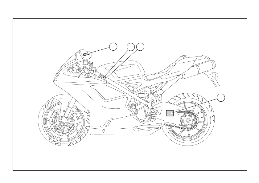
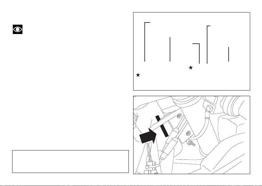
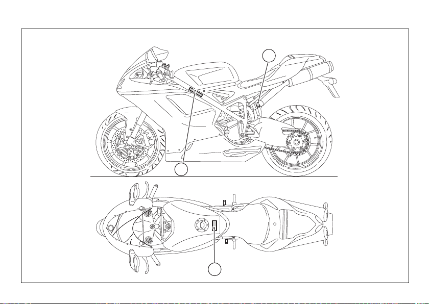
Plate positioning
1
3
2
3
Canada only
fig. 5
20
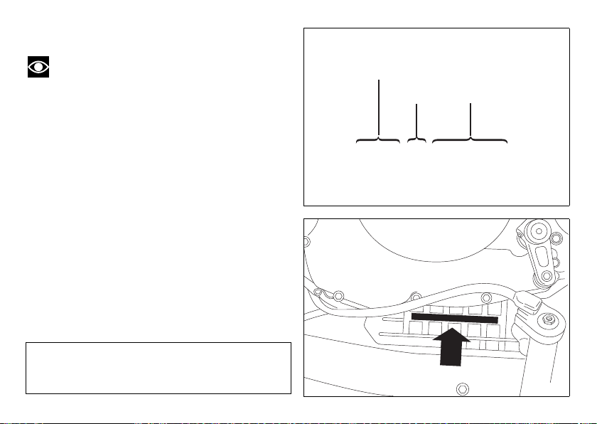
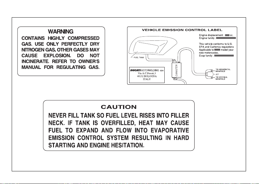
Page 23
31
1.2 ÷ 1.3 in
÷ 33 mm
1
2
3
3
(Canada Only)
fig. 6
21
Page 24
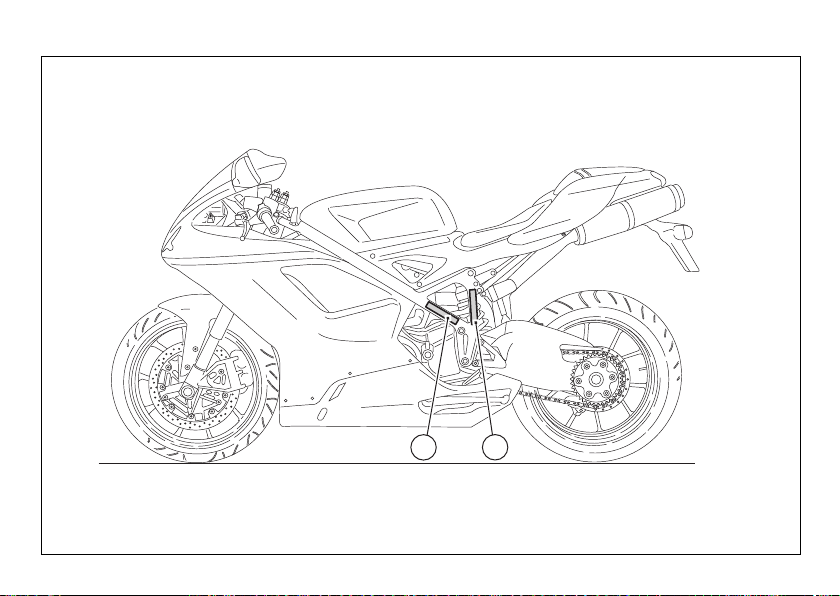
4
5
6
fig. 7
22
Page 25
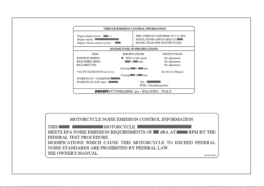
6
5
4
fig. 8
23
Page 26
7
8
fig. 9
24
Page 27
7
8
fig. 10
25
Page 28

Noise and exhaust emission control system information
combustion chamber through the air cleaner and the
throttle body.
Source of Emissions
The combustion process produces carbon monoxide
and hydrocarbons. Control of hydrocarbons is very
important because under certain conditions, they
react to form photochemical smog when subjected
to sunlight.
Carbon monoxide does not react in the same way,
but is toxic. Ducati utilizes lean carburetor settings
and other systems to reduce carbon monoxide and
hydrocarbons.
Exhaust Emission Control System
Exhaust Emission Control System is controlled by an
Electronic Control Unit (ECU), and no adjustments
should be made except idle speed adjustments with
the throttle stop screw. The Exhaust Emission
Control System is separate from the crankcase
emission control system.
Crankcase Emission Control System
The engine is equipped with a closed crankcase
system to prevent discharging crankcase emissions
into the atmosphere. Blow-by gas is returned to the
26
Evaporative Emission Control System
The motorcycles are equipped with an evaporative
emission control system which consists of a charcoal
canister and associated piping. This system prevents
the escape of fuel vapors from the engine and fuel
tank.
Problems that may affect motorcycle
emissions
If you are aware of any of the following symptoms,
have the vehicle inspected and repaired by your local
Ducati dealer.
Symptoms:
Hard starting or stalling after starting.
Rough idle.
Misfiring or backfiring during acceleration.
After-burning (backfiring).
Poor performance (drivability) and poor economy.
Page 29

California emission control warranty statement Your warranty rights and obligations
The California Air Resources Board is pleased to
explain the emission control system warranty on your
MY 2013 motorcycle. In California, new motor
vehicles must be designated, built and equipped to
meet the State's stringent anti-smog standards.
Ducati North America, Inc. must warrant the
emission control system on your motorcycle for the
periods of time listed below provided there has been
no abuse, neglect or improper maintenance of your
motorcycle.
Your emission control system may include parts such
as fuel-injection system, the ignition system, catalytic
converter, and engine computer. Also included may
be hoses, belts, connectors and other emissionrelated assemblies. Where a warrantable condition
exists, Ducati North America, Inc. will repair your
motorcycle at no cost to you including diagnosis,
parts and labor.
Manufacturer’s warranty coverage
- 5 years or 30,000 kilometers (18641 miles),
whichever first occurs.
Owner's warranty responsibilities:
- As the motorcycle owner, you are responsible for
the performance of the required maintenance
listed in your owner's manual. Ducati North
America, Inc. recommends that you retain all
receipts covering maintenance on your
motorcycle, but Ducati North America, Inc. cannot
deny warranty solely for the lack of receipts or for
your failure to ensure the performance of all
scheduled maintenance.
- You are responsible for presenting your
motorcycle to a Ducati dealer as soon as a
problem exists. The warranty repairs should be
completed in a reasonable amount of time, not to
exceed 30 days.
- As the motorcycle owner, you should also be
aware that Ducati North America, Inc. may deny
you warranty coverage if your motorcycle or a part
has failed due to abuse, neglect, improper
maintenance or unapproved modifications.
If you have any questions regarding your warranty
rights and responsibilities, you should contact Ducati
North America, Inc. at 001.408.253.0499 or the
California Air Resource Board at 9528 Telstar
Avenue, El Monte, CA 91731.
27
Page 30
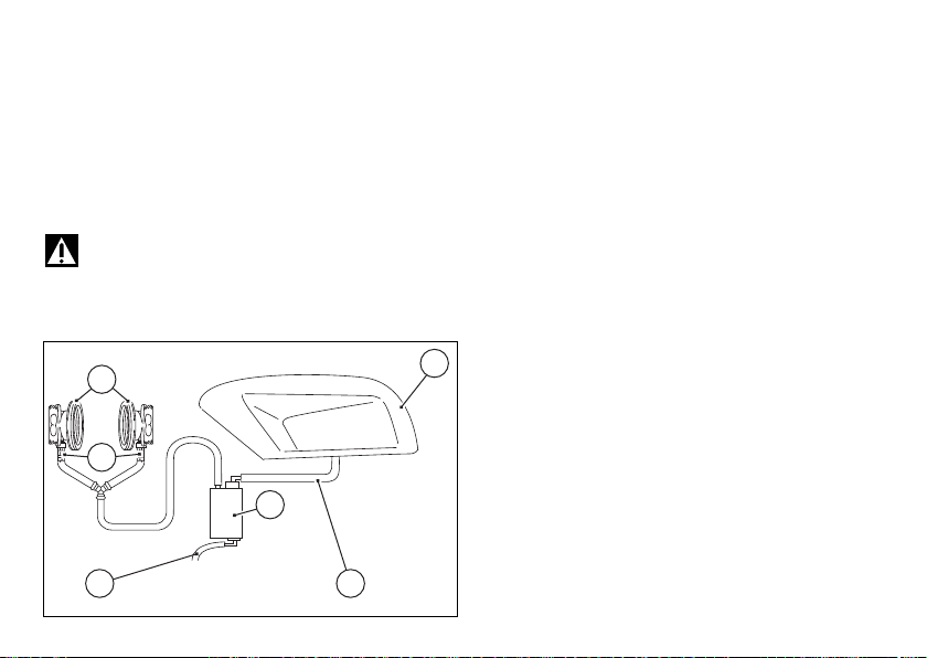
California evaporation emission system
1 5
3
6
2
4
CANISTER
fig. 11
This system consists of (fig. C):
1) Warn air inlet;
2) Canister;
3) Dell’Orto jet;
4) Fuel tank;
5) Breather pipe;
6) Intake manifolds.
Important
In the event of a fuel system malfunction,
contact a Ducati Authorized Service Center.
28
Ducati limited warranty on emission control system
Ducati North America, Inc., 10443 Bandley Drive
Cupertino, California, 95014 warrants that each new
1998 and later Ducati motorcycle, that includes as
standard equipment a headlight, taillight and
stoplight, and is street legal:
A) is designed, built and equipped so as to conform
at the time of initial retail purchase with all applicable
regulations of the United States Environmental
Protection Agency, and the California Air Resources
Board; and
B) is free from defects in material and workmanship
which cause such motorcycle to fail to conform with
applicable regulations of the United States
Environmental Protection Agency or the California Air
Resources Board for a period of use of 30,000
kilometers (18,641 miles) or 5 (five) years from the
date of initial retail delivery, whichever first occurs.
I. Coverage
Warranty defects shall be remedied during
customary business hours at any authorized Ducati
motorcycle dealer located within the United States of
America in compliance with the Clean Air Act and
applicable regulations of the United States
Environmental Protection Agency and the California
Page 31

Air Resources Board. Any part or parts replaced
under this warranty shall become the property of
Ducati.
In the state of California only, emissions related
warranted parts are specifically defined by that
state’s Emissions Warranty Parts List. These
warranted parts are: carburetor and internal parts;
intake manifold; fuel tank, fuel injection system;
spark advance mechanism; crankcase breather; air
cutoff valves; fuel tank cap for evaporative emission
controlled vehicles; oil filler cap; pressure control
valve; fuel/vapor separator; canister; igniters; breaker
governors; ignition coils; ignition wires; ignition
points, condensers, and spark plugs if failure occurs
prior to the first scheduled replacement, and hoses,
clamps, fittings and tubing used directly in these
parts. Since emission related parts may vary from
model to model, certain models may not contain all of
these parts and certain models may contain
functionally equivalent parts.
In the state of California only, Emission Control
System emergency repairs, as provided for in the
California Administrative Code, may be performed by
other than an authorized Ducati dealer. An
emergency situation occurs when an authorized
Ducati dealer is not reasonably available, a part is not
available within 30 days, or a repair is not complete
within 30 days. Any replacement part can be used in
an emergency repair. Ducati will reimburse the
owner for the expenses, including diagnosis, not to
exceed Ducati’s suggested retail price for all
warranted parts replaced and labor charges based on
Ducati’s recommended time allowance for the
warranty repair and the geographically appropriate
hourly labor rate. The owner may be required to keep
receipts and failed parts in order to receive
compensation.
II. Limitations
This Emission Control System Warranty shall not
cover any of the following:
A. Repair or replacement required as a result of
(1) accident,
(2) misuse,
(3) repairs improperly performed or replacements
improperly installed,
(4) use of replacement parts or accessories not
conforming to Ducati specifications which adversely
affect performance and/or
(5) use in competitive racing or related events.
B. Inspections, replacement of parts and other
services and adjustments required for routine
maintenance.
C. Any motorcycle on which odometer mileage has
been changed so that actual mileage cannot be
readily determined.
29
Page 32

III. Limited liability
A. The liability of Ducati under this Emission Control
Systems Warranty is limited solely to the remedying of
defects in material or workmanship by an authorized
Ducati motorcycle dealer at its place of business during
customary business hours. This warranty does not cover
inconvenience or loss of use of the motorcycle or
transportation of the motorcycle to or from the Ducati
dealer. Ducati shall not be liable for any other expenses,
loss or damage, whether direct, incidental, consequential
or exemplary arising in connection with the sale or use of
or inability to use the Ducati motorcycle for any purpose.
Some states do not allow the exclusion or limitation of
any incidental or consequential damages, so the above
limitations may not apply to you.
B. No express emission control system warranty is given
by Ducati except as specifically set forth herein. Any
emission control system warranty implied by law,
including any warranty of merchantability or fitness for a
particular purpose, is limited to the express emission
control systems warranty terms stated in this warranty.
The foregoing statements of warranty are exclusive and
in lieu of all other remedies. Some states do not allow
limitations on how long an implied warranty lasts so the
above limitation may not apply to you.
C. No dealer is authorized to modify this Ducati Limited
Emission Control Systems Warranty.
30
IV. Legal rights
This warranty gives you specific legal rights, and you
may also have other rights which vary from state to
state.
V. This warranty is in addition to the Ducati limited
motorcycle warranty.
VI. Additional information
Any replacement part that is equivalent in
performance and durability may be used in the
performance of any maintenance or repairs.
However, Ducati is not liable for these parts. The
owner is responsible for the performance of all
required maintenance. Such maintenance may be
performed at a service establishment or by any
individual. The warranty period begins on the date the
motorcycle is delivered to an ultimate purchaser.
Ducati North America, Inc..
10443 Bandley Drive
Cupertino, California, 95014
Tel: 001.408.253.0499
Fax: 001.408.253.4099
E-mail: customerservice@ducatiusa.com
Web site: www.ducatiusa.com
Page 33

Instrument Panel (Dashboard)
2
1
5 8 6 3 4 57
fig. 12
Dashboard
1) LCD (see page 33)
2) REVOLUTION COUNTER (rpm).
Indicates engine revs per minute
3) NEUTRAL LIGHT N (GREEN).
Comes on when in neutral position.
4) LOW FUEL LIGHT (YELLOW).
Comes on when fuel is low and there is about a
gallon (3 liters) of fuel left in the tank.
5) TURN INDICATOR LIGHTS (GREEN).
Illuminates and flashes when the turn indicator is in
operation.
6) ENGINE OIL PRESSURE LIGHT (RED).
Comes on when engine oil pressure is too low. It
briefly comes on when the ignition is switched to ON
and normally goes out a few seconds after engine
starts.
May come on briefly when the engine is hot, but
should go off as the engine revs up.
Important
If this light (6) stays on, stop the engine or it may
suffer severe damage.
7) HIGH BEAM LIGHT (BLUE).
Comes on when high beam is on.
8) “ENGINE DIAGNOSIS - EOBD” LIGHT
(AMBER YELLOW).
The engine ECU illuminates this light to indicate
errors and consequent engine lock.
31
Page 34

9) “VEHICLE DIAGNOSIS” LIGHT.
9
10B 10C10A
fig. 13
A
12
B
11
fig. 14
Illuminates when the motorcycle diagnostics detects
a problem.
10)OVER REV LIGHT.
Light 10A: This light comes on steady at 800 rpm
below the limiter threshold.
Lights 10A steady + 10B: These lights come on
steady at 400 rpm below the limiter threshold.
Lights 10A + 10B + 10C: These lights come on
flashing when the limiter threshold is reached.
11) CONTROL SWITCH.
Button used to display and set dashboard parameters
with two positions A “▲“ and B “▼“.
12) HIGH-BEAM FLASH BUTTON FLASH (fig. 14).
The high-beam flash button may also be used to
control the LAP functions and the instrument panel
DDA data logger.
32
Page 35

LCD unit functions
fig. 15
Warning
Adjustments/settings on the dashboard are
strictly to be carried out when the motorcycle is
stationary. Never operate the dashboard controls
while riding the motorcycle.
1) SPEEDOMETER.
Indicates road speed
2) ODOMETER.
Gives total distance covered.
3) TRIP METER.
Indicates distance covered since the meter (TRIP A
and TRIP B) was last reset.
4) TRIP FUEL METER.
Gives total distance traveled on fuel reserve.
5) CLOCK.
6) LAP TIMER.
7) ENGINE RPM INDICATOR (RPM).
8) LAP TIME, TOP SPEED AND MAXIMUM RPM
RECORDING (LAP).
9) BATTERY VOLTAGE INDICATOR (BATT).
10)AIR TEMPERATURE INDICATOR.
11)WATER TEMPERATURE INDICATOR.
Indicates engine coolant temperature.
7
2 3 4
5
1 6
12
8
9
10
11
Important
Stop riding if the temperature reaches the
maximum value, otherwise the engine might be
damaged.
12)SERVICE WARNING (SERV).
The “SERV” message indicates that the vehicle has
covered the distance corresponding to a Scheduled
Maintenance interval. The message is displayed only
at Key-On for 5 seconds. The service indicator will be
reset at an Authorized Ducati Service center during
servicing.
33
Page 36

Important
The instrument panel allows the diagnosis of
the electronic ignition/injection system. Never use
the menus reserved for trained personnel for any
reason. If this function is accidentally accessed, turn
the key to OFF and contact a Ducati Dealer or
Authorized Service center for the necessary checks.
34
Page 37

LCD – How to set/display parameters
ENGINE OFF
ENGINE OFF
ENGINE OFF ENGINE OFF
ENGINE OFF
ENGINE ON
fig. 16
At key-on (key turned from OFF to ON) the
Dashboard activates all the digits of the LCD for 1
second and switches on the indicator lights in
sequence.
It then switches to “normal“ display mode showing
the model indication in place of the odometer readout
and the version (EU, UK, USA, CND, FRA, JAP) for 2
seconds, in place of the road speed readout.
Model is displayed as “scrolling“ text until the engine
is started.
35
Page 38

At Key-On, the Dashboard always shows the
A
B
1
fig. 17
following information (de-activating any previously
activated functions):
ODOMETER
AIR TEMPERATURE.
CLOCK
SPEED
COOLANT TEMPERATURE
ENGINE RPM
At this point, with the button (1, fig. 8) in position B
“▼“, the Odometer readout (TOT) will cycle through
the following functions:
TRIP A
TRIP B
TRIP FUEL (only if active)
until cycling back to the ODOMETER (TOT) function.
ERASE USB
TIME SET
CODE (only if active)
Pressing button (1, fig. 8) in position A “▲“ gives
access to the MENU and the following functions are
displayed one after another:
ERROR (only if at least one error is present)
BATT
RPM
LAP (OFF or ON)
LAP MEM
USB (OFF or ON)
36
Important
This menu is active only if the speed of the
motorcycle is less than 12.4 mph (20 km/h). If this
MENU is open and the speed of the motorcycle
exceeds 12.4 mph (20 km/h), the instrument panel
automatically exits the menu and returns to the initial
display. It is possible to exit the MENU at any time,
however, by pressing button (1, fig. 8) in position A
“▲“, for 3 seconds.
Page 39

Total distance covered indicator:
fig. 18
vs. EU, CND, FRA, JAP
vs. UK, USA
“Odometer“
This function shows the total distance covered by the
vehicle.
This function shows the total distance covered by the
vehicle.
At Key-On the system automatically enters this
function.
The odometer reading is stored permanently and
cannot be reset.
If the distance traveled exceeds 99999 mi (or 99999
km), the value “99999” will be displayed
permanently.
37
Page 40

Air temperature indicator
fig. 19
Diagnosis
Engine
Diagnosis
Engine
vs. EU, CND, FRA, JAP
vs. UK, USA
This function shows the external temperature.
Display limits: -38.2°F to +255.2°F (-39°C to +124°C)
In the event of a sensor FAULT (-40°F/-40°C, 257°F/
+125°C or disconnected), a string of dashes “- - -”
(not flashing) is displayed and the “Engine Diagnosis
- EOBD” light comes on (8, fig. 4).
38
Page 41

Vehicle speed indication
fig. 20
vs. EU, CND, FRA, JAP
vs. UK, USA
This function shows vehicle speed.
The instrument panel receives the actual speed value
(expressed in km/h) from the ECU and displays the
value increased by 8%.
Maximum speed displayed is 186 mph (299 km/h).
Over 186 mph (299 km/h) the instrument panel
displays the dashes “- - -” (not flashing).
39
Page 42

Engine coolant temperature indicator
fig. 21
Engine
Diagnosis
STEADY READING
STEADY READING
STEADY READING
FLASHING DATUM
FLASHING DATUM
STEADY READING
STEADY READING
STEADY READING
FLASHING DATUM
FLASHING DATUM
Engine
Diagnosis
vs. EU, CND, FRA, JAP
vs. UK, USA
Indicates engine coolant temperature.
- If reading is -40 °F (-40 °C) or less, the display
shows a string of flashing dashes (“- - -“) and the
“Engine diagnosis - EOBD“ light (8, fig. 4) comes
on;
- if the reading is between -38°F and +102°F (-39°C
and +39°C) “LO” is shown on the dashboard
(steady);
- if the reading is between +104°F and +248°F
(+40°C and +120°C) the reading appears on the
dashboard (steady);
- if the reading is between +250°F and +255°F
(+121°C and +124°C) “HI” is shown on the
dashboard (flashing);
- If reading is +257 °F (+125 °C) or more, the
display shows a string of flashing dashes (“---“)
and the “Engine diagnosis - EOBD“ light (9, fig. 4)
comes on;
- In the event of a sensor “error“, a string of
flashing dashes (“---“) is shown and the “Engine
diagnosis - EOBD“ light comes on (8, fig. 4).
40
Page 43

Partial trip meter “TRIP A”
fig. 22
vs. EU, CND, FRA, JAP
vs. UK, USA
This function shows the partial distance covered by
the vehicle.
Holding the button (1, fig. 8) pressed for 3 seconds in
position B “▼” when this function is displayed resets
the trip meter.
When the reading exceeds 999.9, distance traveled
is reset and the meter automatically starts counting
from 0 again.
41
Page 44

Partial trip meter “TRIP B“
fig. 23
vs. EU, CND, FRA, JAP
vs. UK, USA
This function shows the partial distance covered by
the vehicle.
Holding the button (1, fig. 8) pressed for 3 seconds in
position B “▼” when this function is displayed resets
the trip meter.
When the reading exceeds 999.9, distance traveled
is reset and the meter automatically starts counting
from 0 again.
42
Page 45

Distance traveled on fuel reserve:
fig. 24
vs. EU, CND, FRA, JAP
vs. UK, USA
“TRIP FUEL“
This function shows the distance traveled on fuel
reserve.
When the fuel light comes on, the display
automatically switches to the “TRIP FUEL“ indicator.
Trip fuel reading remains stored even after Key-Off
until the vehicle is refueled.
Count is interrupted automatically as soon as fuel is
topped up to above minimum level.
When the reading exceeds 999.9, the counter is
reset and the count restarts automatically.
43
Page 46

Maintenance indicator (SERV)
fig. 25
It shows service intervals (service).
The message “SERV” is displayed at the following
intervals:
after the first 621 mi (1000 km) on the odometer;
every 7456 mi (12000 km) on the odometer.
The message is displayed only at Key-On for 5
seconds.
When the service indicator appears, contact a Ducati
Dealer or Authorized Service center.
44
Page 47

Battery voltage indicator (BATT).
STATUS 1
STATUS 2
STATUS 3
STEADY STEADY
FLASHING FLASHING
FLASHING FLASHING
fig. 26
This function describes the battery voltage indicator.
To display this function, go into the menu and select
the “BATT” page.
The dashboard displays the battery voltage
information as follows:
- if voltage is between 12.1 and 14.9 Volt, the
reading is on steady;
- if voltage is between 10.0 and 12.0 Volt or
between 15.0 and 16.0 Volt, the reading will be
flashing;
- if battery voltage is equal or less than 9.9 Volt,
“LO“ is shown flashing and the “Vehicle
Diagnosis“ light comes on (9, fig. 4);
- if battery voltage is equal or greater than 16.1 Volt,
“HI“ is shown flashing and the “Vehicle
Diagnosis” light comes on (9, fig. 4).
45
Page 48

Engine idle RPM setting (RPM)
fig. 27
This function describes engine idle setup.
To display this function, go into the menu and select
the “RPM” page.
In addition to the upper rev counter scale, the
instrument panel also displays engine rpm
numerically so that you can adjust the idle speed
more precisely.
46
Page 49

LAP timer
fig. 28
This function lets you display lap times.
To enable this function, enter the menu and set the
LAP function to “On“ by holding button (1, fig. 8) in
position B “▼“ pressed for 3 seconds.
The lap timer is started and stopped using the highbeam flasher button FLASH (12, fig. 5) on the LH
switch.
When the LAP function is active, each time you press
the FLASH button, the display will show the lap time
for 10 seconds, before reverting to normal mode.
You can save a maximum of 30 laps in the memory.
Once the memory is full, the display no longer stores
lap times when the FLASH headlight button is
pressed, and the flashing message “FULL” is shown
on the display for 3 seconds until the times are reset.
47
Page 50

When the LAP function is set to Off in the menu, the
fig. 29
Press Flash
After 10 secs.
Press Flash
After 10 secs.
current “lap“ is not stored.
If the LAP function is active and the display is
suddenly turned off (Key-Off), the LAP function will
be automatically disabled (even if the lap timer was
active, the current “lap“ is not stored).
In case the time is never “stopped“, after 99
minutes, 59 seconds, 99 hundredths, the timer starts
from 0 (zero) and the time counting continues until
the function is disabled.
If however the LAP function is switched on and the
memory has not been cleared, but fewer than 30 laps
have been saved (e.g. 18 laps), the instrument panel
will store any remaining laps until the memory is full
(in this case, it will store an additional 12 laps).
This function only displays lap times; but other data
are also saved (MAX speed, MAX rpm, rev limiter if
reached) for viewing at a later date in the Lap
Memory function.
48
Page 51

Stored data display (LAP Memory)
A
B
B
A
A
A
B
B x 19
B x 19
fig. 30
B = ON for 3
secs.
Resets lap
times in
memory
It displays data stored using the LAP function: lap
time, MAX speed and MAX rpm.
To view stored lap times, enter the menu and go to
page “LAP MEM“.
Holding button (1, fig. 8) in position B “▼“ pressed
for 3 seconds in this menu page accesses the “1st
lap“ view mode. The display will show the lap
number, lap time, the MAX speed and the MAX rpm
reached for the lap in question.
Press button (1, fig. 8) in position B “▼“ repeatedly
to scroll through the 30 laps stored until returning to
the 1st lap.
If you press button (1, fig. 8) in position B “▼“ for 3
seconds while the saved times are displayed, the
display immediately resets all the saved times and
the LAP function is disabled automatically, if active.
The MAX speed saved is the maximum speed
indicated on the display in Lap function.
If MAX speed reading exceeds 186 mph (299 Km/h)
while the information is stored, actual speed reading
is displayed (example: 316 Km/h).
If the memory is empty, the display shows the 30 lap
times with the lap timer reading “00.00.00”, MAX
RPM = 0 and MAX speed = 0.
49
Page 52

If the engine reached one of the two thresholds
before the limiter or the limiter threshold during a lap,
the corresponding lights (10, fig. 4) come on while
viewing stored lap times.
50
Page 53

DDA data acquisition
fig. 31
This function activates the DDA analyzer (not fitted
for this model, but available at Ducati sales network):
the data logger must be connected to vehicle wiring.
To enable this function, enter the menu and set the
“DDA“ data acquisition to “On“ by holding the
button (1, fig. 8) in position B “▼“ pressed for 3
seconds. The START/STOP control for the data
logger lap separator is the high-beam flash button
FLASH (12, fig. 5) on the LH switch. If the DDA
function is active and the display is suddenly
switched off (Key-Off), the function is switched off
automatically.
Note
Online assistance is available to Ducati Data
Analyzer (DDA) owners (http://dda.prosa.com). This
service will provide anything necessary to correctly
use the DDA with your PC: both for the device and
the software for analyzing the recorded data.
Warning
After use, disconnect the DDA from the main
wiring harness.
51
Page 54

Erase DDA
DDA = ON
fig. 32
Displayed for 2 secs.
Displayed for 10 secs.
Displayed for 2 secs.
B = ON for 3 secs.
YES
NO
This function deletes all data from the DDA (not fitted
for this model, but available at Ducati sales network):
the data logger must be connected to vehicle wiring.
To erase data, enter the menu page “Erase DDA“.
If you press button (1, fig. 8) in position B “▼“ for 3
seconds and the DDA is not acquiring data, the
message “WAIT…” is shown on the display for 10
seconds; after these 10 seconds, message “Erase
OK“ is displayed for 2 seconds to confirm that the
data in the DDA data logger have been erased.
If the button (1, fig. 8) is pressed in position B “▼“
for 3 seconds while the DDA data logger is acquiring
data, the data logger memory is not erased and the
display shows message “FAIL“ for 2 seconds.
52
Page 55

Clock setting function
fig. 33
B = ON for 3 secs.
Flashing
Flashing
Flashing
Flashing
Flashing
Flashing
This function is used to set the clock time.
To set the clock, select the “TIME SET” page from
the menu.
Holding button (1, fig. 8) in position B “▼“ pressed
for 3 seconds in this menu page gives access to the
setup mode.
When you access this function, the text “AM“
flashes; if you press button (1, fig. 8) in position B
“▼” the text “PM” flashes; if you press button (1,
fig. 8) in position B “▼” mode will go back to
previous setting (if it is 00:00, when toggling from
“AM” to “PM”, 12:00 will be displayed).
pressing button (1, fig. 8) in position A “▲” accesses
the hour setting mode; the hours start to flash. Each
time you press the button in position B “▼“ the digit
will increase by 1 hour; if the button is held pressed
down in position B “▼“, the digit will increase by 1
hour every second (when the button is held pressed,
the hours do not flash).
B
B
B
B
B
B
A
A
A
A
A
Pressing button (1, fig. 8) in position A “▲”, gives
access to the minute setting mode; minutes start to
flash. Each time you press the button in position B
“▼“, the digit will increase by 1 minute. If you hold
the switch down in position B “▼”, the count
increases cyclically in steps of 1 minute every
A
53
Page 56

second. If the button is held depressed in position B
“▼“ for over 5 seconds, minutes will increase by 1
minute every 100 ms (while the button is held
depressed in position B “▼“ seconds do not flash).
Pressing the button in position A “▲” exits setup
mode and the new time is displayed.
54
Page 57

Dashboard diagnosis
Important
The instrument panel runs system diagnostics
after 60 seconds from the last Key-Off.
Any abnormal vehicle behavior is displayed.
If more errors are present, they are displayed one by
one every 3 seconds.
The table below shows the errors that can be
displayed.
Warning
When one or more errors are displayed, always
contact a Ducati Dealer or Authorized Service Center.
WARNING
LIGHT
ERROR MESSAGE ERROR
COIL 8.1 Horizontal cylinder coil error
COIL 8.2 Horizontal cylinder coil error
COIL 9.1 Vertical cylinder coil error
COIL 9.2 Vertical cylinder coil error
COIL 10.1 Horizontal cylinder coil error
55
Page 58

WARNING
LIGHT
56
ERROR MESSAGE ERROR
COIL 10.2 Horizontal cylinder coil error
COIL 11.1 Vertical cylinder coil error
COIL 11.2 Vertical cylinder coil error
INJE 12.1 Horizontal cylinder injector error
INJE 12.2 Horizontal cylinder injector error
INJE 13.1 Vertical cylinder injector error
INJE 13.2 Vertical cylinder injector error
INJE 14.1 Horizontal cylinder injector error
INJE 14.2 Horizontal cylinder injector error
INJE 15.1 Vertical cylinder injector error
Page 59

WARNING
LIGHT
ERROR MESSAGE ERROR
INJE 15.2 Vertical cylinder injector error
PUMP 16.0 Fuel pump relay error
FAN 18.1 Fan relay error
FAN 18.2 Fan relay error
STRT 19.1 Solenoid starter error
STRT 19.2 Solenoid starter error
STEP. 21.1 Stepper motor error
STEP. 21.2 Stepper motor error
STEP. 21.3 Stepper motor error
LAMB. 22.1 Lambda heaters error
57
Page 60

WARNING
LIGHT
58
ERROR MESSAGE ERROR
LAMB. 22.2 Lambda heaters error
EXVL 23.1 Exhaust valve motor error
EXVL 23.2 Exhaust valve motor error
EXVL 23.3 Exhaust valve motor error
EXVL 23.4 Exhaust valve motor error
TPS 1.1 Throttle position sensor error
TPS 1.2 Throttle position sensor error
PRESS 2.1 Pressure sensor error
PRESS 2.2 Pressure sensor error
T. WAT 3.1 Water temperature sensor error
Page 61

WARNING
LIGHT
ERROR MESSAGE ERROR
T. WAT 3.2 Water temperature sensor error
AIR 4.1 Air temperature sensor error
AIR 4.2 Air temperature sensor error
BATT 5.1 Battery voltage error
BATT 5.2 Battery voltage error
LAMB 6.1 Lambda sensor error
TILT 6.2 Lambda 2 sensor error
DTC 8.0 Traction control unit error
ECU 30.0 Engine control unit error
PK.UP 34.0 pick up sensor error
59
Page 62

WARNING
LIGHT
60
ERROR MESSAGE ERROR
SPEE. 36.0 Speed sensor error
IMMO 37.0 Immobilizer error
IMMO 37.1 immobilizer error
IMMO 37.3 Immobilizer error
IMMO 37.5 Immobilizer error
CAN 38.0 CAN communication line error
Page 63

Instrument panel backlighting
The instrument panel backlighting is always activated
by Key-On.
The instrument panel is equipped with sensors that
detect the ambient light level and at night reduce the
maximum backlighting level by 20% to prevent glare.
Headlight “smart” auto-off
This function allows you to reduce current
consumption from the battery by automatically
managing headlight switching-off. The device is
enabled in three instances:
- In case 1, when the key is turned from OFF to ON
and the engine is not started within 60 seconds,
the headlight is turned off and will be turned back
on next time you start the engine.
- In case 2, after the vehicle has been running with
the headlights on and the engine is stopped using
the RUN-STOP button on the RH switch.
In this case, 60 seconds after stopping the engine,
the headlight is turned off and will be turned back
on next time you start the engine.
- In case 3, when starting up the engine, the
headlight is turned off and back on as soon as the
engine is started.
Headlight “smart” switch-on
This function allows programmed activation of the
headlight even with the motorcycle off (Key-Off).
The instrument panel stays active for 60 seconds
soon after Key-Off, and the headlight can be
switched on by pressing switch (1, fig. 8) in position
B “▼”.
During these 60 seconds, each time the button (1,
fig. 8) is pressed in position B “▼“, the instrument
panel allows to activate the headlight for 30 seconds;
each time the button is pressed, the activation time
will be added up, up to a maximum of 180 seconds,
corresponding to pressing the button (1, fig. 8) in
position B “▼” 6 times.
After the first time you press switch (1, fig. 8) in
position B “▼”, the period of 30 seconds starts, thus
switching on the headlight. Further switch-on time
can be added only if you press the switch again
within these 30 seconds. If the 30 seconds have
elapsed, no further time can be added, and the
instrument panel will switch off the headlight.
61
Page 64

To reset this function, you must perform at least one
Key-On/ Key-Off cycle.
If there is a sudden battery cutoff while the function
is active, the instrument panel will disable the
function when the voltage is restored (the instrument
panel is disabled for 60 seconds).
62
Page 65

The Immobilizer system
B
1
fig. 34
For improved antitheft protection, the motorcycle is
equipped with an IMMOBILIZER, an electronic
system that inhibits engine operation whenever the
ignition switch is turned off.
Housed in the handgrip of each ignition key is an
electronic device that modulates an output signal.
When the ignition is turned on this signal is
generated by a special antenna incorporated in the
switch and changes every time. The modulated
signal represents the “password” (which is changed
at each start-up) by which the ECU recognizes the
ignition key. The ECU will only allow the engine to
start if it recognizes this password.
Keys (fig. 34)
The Owner receives a set of keys comprising:
- 2 (BLACK) keys B
These keys contain the “immobilizer system code“.
Note
Your Ducati dealer may ask you to produce your
Code Card in order to carry out certain servicing
operations.
The black keys (B) are regular ignition keys and are
used to:
- start up the engine.
- open the fuel tank filler plug.
- open the seat lock.
Note
The two keys have a small plate (1) attached
that reports their identification number.
Warning
Keep the keys separate, and store the tag (1) in
a safe place.
It is also advisable to use only one of the keys to start
the motorcycle.
63
Page 66

Code card
fig. 35
A
fig. 36
The CODE CARD (fig. 35) supplied with the keys
reports an electronic code (A, fig. 36) to start the
engine in the event it fails to start after KEY-ON
because the immobilizer system inhibited the
ignition.
Warning
Keep the CODE CARD in a safe place. However,
it is advisable to keep the electronic code printed on
the CODE CARD handy when you ride your
motorcycle, in case it is necessary to enable the
engine through the procedure described below. This
procedure lets you disable the “engine block”
function - indicated by the amber “Vehicle diagnosis“
light (9,fig. 12) coming on - in the event of problems
with the immobilizer system.
This operation is only possible if the electronic code
indicated on the code card is known.
Warning
Your dealer will ask you to produce the Code
Card in order to reprogram or replace a key.
64
Page 67

Immobilizer override procedure
A
A
A
A
A
B
B
B
B
B
B
B
B
B
fig. 37
B = ON for 3
secs.
Entered
code
OK?
No
Ye
Should the immobilizer LOCK (disable) the engine,
you can perform the “Immobilizer Override”
procedure from the instrument panel by entering the
relevant function as described below.
Enter the menu and go to page “CODE“.
Note
This menu should only be active when at least
one Immobilizer error is present.
This menu page shows a default “00000“ code. If
you press button (1, fig. 8) in position B “▼“ for 3
seconds, you will access the procedure for entering
the electronic code given on the Code Card.
65
Page 68

Entering the code:
when you access this function, the first digit on the
left will flash.
Button (1, fig. 8):
Each time you press the button in position B “▼“ the
digit will increase by one unit every second;
pressing the button in position A “▲” accesses
setting mode of the second digit which will start to
flash. Each time you press the button in position B
“▼“ the digit will increase by one unit every second;
pressing the button in position A “▲” accesses
setting mode of the third digit which will start to
flash. Each time you press the button in position B
“▼“ the digit will increase by one unit every second;
pressing the button in position A “▲” accesses
setting mode of the fourth digit which will start to
flash. Each time you press the button in position B
“▼“ the digit will increase by one unit every second;
pressing the button in position A,▲” accesses
setting mode of the fifth digit which will start to flash.
Each time you press the button in position B “▼“ the
digit will increase by one unit every second;
press in position A “▲” to confirm the code.
66
If the code has been entered correctly, the word
“CODE” and the code you just entered will flash for
4 seconds. The “Vehicle diagnosis“ light (9, fig. 4)
will turn off; the instrument panel automatically exits
the menu and the engine start-up inhibition is
temporarily overridden.
If the error is still present, at the next Key-On the
instrument panel error and the inhibited status will
persist.
If the code is not entered correctly, the instrument
panel reverts to the “CODE“ menu and displays the
default “00000“ code.
Page 69

Operation
When the ignition key is turned to OFF, the
immobilizer inhibits engine operation. When the
ignition key is turned back to ON to start the engine,
the following happens:
1) if the code is recognized, the immobilizer enables
engine ignition. Press the START button (2, fig. 43),
to start the engine;
2) if the “Vehicle diagnosis “ light (9, fig. 4) comes on
and the page with the message “Error IMMO“ is
displayed when you press button (1, fig. 8) in position
“▼“ it means that the code was not recognized.
When this is the case, turn the ignition key back to
OFF and then to ON again. If the engine still does not
start, try with another black key. If the other key does
not work out either, contact the Ducati Service
network.
Warning
Any important shock might damage the
electronic components fitted into the key.
Use only one key during the procedure. Failure to do
so might prevent the system from recognizing the
code of the key in use.
Duplicate keys
If you need any duplicate keys, contact the Ducati
Service network with all the keys you have left and
the CODE CARD.
The Ducati Service Center will program all the new
keys as well as any keys you already have.
You may be asked to provide proof that you are the
legitimate owner of the motorcycle.
The codes of any keys not submitted will be wiped
off from the memory to make those keys
unserviceable in case they have been lost.
Note
If you sell your motorcycle, do not forget to give
all keys and the CODE CARD to the new owner.
67
Page 70

Service menu - unit of measurement (UNIT SET)
This function allows you to select the units of
measurement displayed on the instrument panel.
To enter the service menu, push button (1, fig. 17) in
position A“▲” while turning the key from “Off“ to
“On“.
Note
Within this menu all other functions are
excluded and motorcycle starting is disabled.
The first function displayed is the “Immobilizer
Reprogramming” procedure (Cod REPR). Press the
button (1, fig. 17) in position A “▲” or B “▼” to
select the “Setting Special” (Set UNIT) function.
Now press button (1, fig. 17) in position B “▼“ for
3 seconds.
Each time you press button (1, fig. 17) in position B
“▼“ the instrument panel scrolls through the
following sequence of options, which flash on the
display:
68
UNIT OF MEASUREMENT
Country
standard
EU Km/h °C Km
EN Mph °C miles
USA Mph °F miles
CND Km/h °C Km
FRA Km/h °C Km
JAP Km/h °C Km
ECU ld. The instrument panel sets units of
If you press the button (1, fig. 17) in position B “▼“
for 3 seconds, the option currently displayed will be
saved to memory and the word “MEM” will appear.
Upon the following Key-On the instrument panel will
be set to the new settings.
Speed Air
temperature
measurement according to ECU
information
Odometer/
trip meters
Page 71

fig. 38
Key OFF to quit
press B for 3 sec.
Press A
Press B
press B for 3 sec.
press B for 3 sec.
press B for 3 sec.
press B for 3 sec.
press B for 3 sec.
press B for 3 sec.
Press B
Press B
Press B
Press B
Press A
Press A
Press A
Press A
Press A
69
Page 72

Controls
1
4
3
2
9
8
5
7
6
fig. 39
Warning
This section shows the position and function of
the controls used to ride the motorcycle. Be sure to
read this information carefully before you use the
controls.
Position of motorcycle controls (fig. 39)
1) dashboard.
2) Key-operated ignition switch and steering lock.
3) Left hand handlebar switch.
4) Clutch lever.
5) Rear brake pedal.
6) Right hand handlebar switch.
7) Throttle twistgrip.
8) Front brake lever.
9) Gear change pedal.
70
Page 73

Key-operated ignition switch and
A
B
C
D
fig. 40
steering lock
It is located in front of the fuel tank and has four
positions:
A) ON: enables lights and engine operation;
B) OFF: disables lights and engine operation;
C) LOCK: the steering is locked;
D) P: parking light on and steering locked.
(fig. 40)
Note
To move the key to the last two positions, press
it down before turning it. The key can be removed in
positions (B), (C) and (D).
71
Page 74

LH switch (fig. 41)
1 2
4
3 5
fig. 41
1) Dip switch, two-position light selector switch:
position = low beam on;
position = high beam on.
2) Button = three-position turn indicator:
central position = off;
position = left turn;
position = right turn.
To cancel turn indicators, push in once switch returns
to central position.
3) Button = warning horn.
4) Button = high-beam flasher (FLASH) and
instrument panel control.
5) Two-position instrument panel control switch:
position “▲”;
position “▼”.
72
Page 75

Clutch lever
2 1
fig. 42
Lever (1) disengages the clutch. It features a dial
adjuster (2) for lever distance from the twistgrip on
handlebar.
The lever distance can be adjusted through 10 clicks
of the dial (2). Turn clockwise to increase lever
distance from the twistgrip. Turn the adjuster counter
clockwise to decrease lever distance.
When the clutch lever (1) is operated, drive from the
engine to the gearbox and the drive wheel is
disengaged. Using the clutch properly is essential to
smooth riding, especially when moving off.
Warning
Set clutch lever when motorcycle is stopped.
Important
Using the clutch properly will avoid damage to
transmission parts and spare the engine.
Note
It is possible to start the engine with the side
stand down and the gearbox in neutral. When
starting the bike with a gear engaged, pull the clutch
lever (in this case the side stand must be up).
73
Page 76

RH switch (fig. 43)
3
1
2
fig. 43
1) ENGINE STOP switch, two positions:
position “ ” (RUN) = run;
position “ ” (OFF) = stop.
Warning
This switch is mainly intended for use in
emergency cases when you need to stop the engine
quickly. After stopping the engine, take the switch
back to the “ ” position to enable starting.
Important
Stopping the engine using switch (1) after riding
with the lights on and leaving the ignition key in the
ON position, may run the battery flat as the lights will
remain on.
2) Button = engine start.
Throttle twistgrip (fig. 43)
The twistgrip (3) on the right handlebar opens the
throttles. When released, it will spring back to the
initial position (idling speed).
74
Page 77

Front brake lever (fig. 44)
21
fig. 44
Pull in the lever (1) towards the twistgrip to operate
the front brake. The system is hydraulically operated
and you just need to pull the lever gently.
The control lever (1) features a dial adjuster (2) for
lever distance from the twistgrip on handlebar
adjustment.
The lever distance can be adjusted through 10 clicks
of the dial (2). Turn clockwise to increase lever
distance from the twistgrip. Turn the adjuster counter
clockwise to decrease lever distance.
75
Page 78

Rear brake pedal (fig. 45)
1
fig. 45
6
5
4
3
2
1
N
fig. 46
Push down on the pedal (1) to apply the rear brake.
The system is hydraulically operated.
Gear change pedal (fig. 46)
When released, the gear change pedal automatically
returns to rest position N in the center. This is
indicated by the dashboard light N (3, fig. 12) coming
on.
The pedal can be moved:
down = press down the pedal to engage the 1
and to shift down. The N light will go out;
upwards= lift the pedal to engage 2
rd
3
, 4th, 5th and 6th gears.
Each time you move the pedal you will engage the
next gear.
st
gear
nd
gear and then
76
Page 79

Setting the gear change and rear brake
2 1 3
fig. 47
pedals
The gear change and rear brake pedals can be
adjusted to suit the preferred riding position of each
rider.
To adjust the position, proceed as follows:
hold the linkage (1) and slacken the lock nuts (2) and
(3).
(fig. 47 and fig. 48)
Note
Nut (2) has a left hand thread.
Fit an open-end wrench to hexagonal element of
linkage (1) and rotate until setting pedal in the desired
position.
Tighten both check nuts onto linkage.
77
Page 80

To adjust the position, proceed as follows:
7
4
5
6
fig. 48
Loosen counter nut (4).
Turn pedal stroke adjusting screw (5) until pedal is in
the desired position.
Tighten the check nut (4) to 1.7 lbf-ft (2.3 Nm).
Operate the pedal by hand to check that there is
0.05÷0.07 in (1.5÷2 mm) of free play before the
brake bites.
If not so, set the length of cylinder linkage as follows.
Loosen the check nut (6) on cylinder linkage.
Tighten linkage into fork (7) to increase play, or
unscrew linkage to reduce it.
Tighten the check nut (6) to 5.5 lbf-ft (7.5 Nm) and
check free play again.
78
Page 81

Main components and
3
4
15
6
5 2
8
6
7
9
fig. 49
devices
Position on the vehicle (fig. 49)
1) Tank filler plug.
2) Seat lock.
3) Side stand.
4) Steering damper
5) Rearview mirrors.
6) Front fork adjusters.
7) Rear shock absorber adjusters.
8) Exhaust muffler (see “Warning” on page 95).
9) Catalytic converter.
79
Page 82

Fuel tank plug (fig. 50)
1
fig. 50
Opening
Lift the protection lid (1) and fit the ignition key into
the lock. Turn the key clockwise 1/4 turn to unlock.
Lift the plug.
Closing
Refit the plug with the key in it and push it down into
its seat. Turn the key counter-clockwise to the initial
position and remove it. Close the lock protection lid
(1).
Note
The plug can only be closed with the key in.
Warning
Always make sure you have properly refitted
(see page 96) and closed the plug after refueling.
80
Page 83

Seat lock
2
1
1
1
0
0
fig. 51
3
4
5
fig. 52
Opening (fig. 51)
Insert the key into the seat lock (1) and turn it
clockwise until the seat catch disengages with an
audible click.
Moderately pull the rear end of the seat (2) up and
raise until it can be extracted.
Closing (fig. 52)
Insert the hooks (3) on the base of the seat under the
rear subframe.
Push the passenger seat until pin (4) clicks in place
inside latch (5).
Pull the passenger seat moderately upwards to make
sure it is correctly and firmly engaged.
81
Page 84

Side stand (fig. 53)
2
1
fig. 53
Important
Before lowering the side stand, make sure that
the supporting surface is hard and flat.
Do not park on soft or pebbled ground or on asphalt
melted by the sun, etc. or else the motorcycle may
fall over.
When parking downhill, always position the
motorcycle with the rear wheel facing downhill.
To pull down the side stand, hold the motorcycle
handlebar with both hands and push down on the
side stand (1) with your foot until it is fully extended.
Tilt the motorcycle until the side stand is resting on
the ground.
Warning
Do not sit on the motorcycle when it is
supported on the side stand.
To move the side stand to its rest position (horizontal
position), lean the motorcycle to the right while lifting
the thrust arm (1) with your foot.
82
Note
Check for proper operation of the stand
mechanism (two springs, one into the other) and the
safety sensor (2) at regular intervals.
Note
The engine can be started with the side stand
down and the gearbox in neutral. If starting with a
gear engaged, pull in the clutch lever (in this case the
side stand must be up).
Page 85

Steering damper (fig. 54)
fig. 54
It is located up front before the tank and is secured to
frame and steering head.
It provides stable and accurate steering, improving
the motorcycle's handling response under any
conditions.
83
Page 86

Front fork adjusters
1
A
2
fig. 55
The front fork used on this motorcycle has rebound,
compression and spring preload adjustment.
This adjustment is done using the outer adjusters:
1) to adjust the rebound damping (fig. 55);
2) to adjust the preload of the inner springs (fig. 55);
3) to adjust the compression damping (fig. 56).
Position the motorcycle on its side stand so that it is
stable.
Turn the adjuster (1) on every fork leg top with a
suitable wrench to adjust rebound damping.
As you turn the adjusting screws (1 and 3), you will
hear them click. Each click identifies a setting. The
stiffest damping setting is obtained with the adjuster
turned fully clockwise to the “0” position. Start with
this position and turn counter-clockwise. Count the
clicks, which correspond to position 1, 2 and so forth.
84
Page 87

STANDARD factory setting is as follows:
3
fig. 56
compression:
3/4 turns;
rebound:
12 clicks.
Spring preload: (A, fig. 55): 0.7 in (18 mm).
To change the preload of the spring inside each fork
leg, turn the hex. adjuster (2, fig. 55) with a 0.9-in (22
mm) hexagon wrench.
Important
Regulate the adjusters on both legs to the same
positions.
85
Page 88

Rear shock absorber adjusters (fig. 57)
2
3
1
fig. 57
The rear shock absorber has outer adjusters that
enable you to adjust your motorcycle to the load.
The adjuster (1) on the left side of the connection
holding the shock absorber to the swinging arm
controls rebound damping.
The adjuster (2) on the shock absorber expansion
reservoir controls compression damping.
Turning the adjusters (1 and 2) clockwise gives
harder damping, turning counter-clockwise gives
softer damping.
STANDARD setting:
from fully closed (clockwise) loosen:
adjuster (1) by 2 turns.
adjuster (2) by 2 turns.
Spring preload: 0.9 in (20 mm).
Two ring nuts (3) located on the top section of the
shock absorber are used to adjust the outer spring
preload. To adjust the spring preload, loosen the top
ring nut. Then TIGHTEN or SLACKEN the lower ring
nut to INCREASE or DECREASE spring preload.
86
Page 89

Once preload has been set as required, tighten the
upper ring nut.
Warning
Use a specific pin wrench to turn the preload
adjusting nut. Be careful when turning the nut with
the wrench, as the pin may slip out of the ring nut
recess and you may hurt your hand hitting
motorcycle parts.
Warning
The shock absorber is filled with gas under
pressure and may cause severe damage if taken
apart by someone who is unskilled.
If you intend to transport a passenger and baggage,
preload the shock absorber spring to the maximum to
improve the dynamic performance of the motorcycle
and to avoid possible interference with ground. You
may find that rebound damping needs adjusting as
well.
87
Page 90

Riding the motorcycle
Break-in recommendations
Maximum rpm (fig. 58)
Rotation speed for Break-in period and during
standard use (rpm):
1) Up to 621 mi (1000 km);
2) From 621 to 1553 mi (1000 to 2500 km).
Up to 621 mi (1000 km)
During the first 621 mi (1000 km), keep an eye on the
rev counter. It should never exceed
5,500÷6,000 rpm.
During the first few hours of riding, it is advisable to
run the engine at varying load and rpm, though still
within recommended limit.
To achieve this, roads with plenty of bends and even
slightly hilly areas are ideal for the most efficient
break-in of the engine, brakes and suspensions.
88
For the first 62 mi (100 km), use the brakes gently.
Avoid sudden or prolonged braking. This will allow
the friction material on the brake pads to bed in
against the brake disks.
For all mechanical parts of the motorcycle to adapt to
one another and above all not to adversely affect the
life of basic engine parts, it is advisable to avoid harsh
accelerations and not to run the engine at high rpm
for too long, especially uphill.
It is also advisable to inspect the drive chain
frequently and lubricate as required.
Page 91

621 in (1000 mm) to 1553 mi (2500 km)
0 ÷ 1000 Km
1000 ÷ 2500 Km
fig. 58
At this point, you can squeeze some more power out
of your engine. However never exceed
7000 min
-1
.
Important
During the entire Break-in period, carefully
observe the indications on the scheduled
maintenance chart and servicing recommendations
in the Warranty Booklet. Failure to follow these
instructions releases Ducati Motor Holding S.p.A.
from any liability whatsoever for any engine damage
or shorter engine life.
Strict observance of Break-in recommendations will
ensure longer engine life and reduce the likelihood of
overhauls and tune-ups.
89
Page 92

Pre-ride checks
Warning
Failure to carry out these checks before riding
may lead to motorcycle damage and injury to rider
and passenger.
Before riding, perform a thorough check-up on your
bike as follows:
FUEL LEVEL IN THE TANK
Check the fuel level in the tank. Fill tank if needed
(page 96).
ENGINE OIL LEVEL
Check oil level in the sump through the sight
glass. Top up if needed (page 120).
BRAKE AND CLUTCH FLUID
Check fluid level in the relevant reservoirs (page 104).
COOLANT
Check coolant level in the expansion reservoir. Top
up if needed (page 103).
TIRE CONDITION
Check tire pressure and condition (page 118).
CONTROLS
Work the brake, clutch, throttle and gear change
controls (levers, pedals and twistgrip) and check for
proper operation.
90
LIGHTS AND INDICATORS
Make sure lights, indicators and horn work properly.
Replace any burnt-out bulbs (page 112).
KEY LOCKS
Ensure that fuel filler plug (page 80) and seat
(page 81).
SIDE STAND
Make sure side stand operates smoothly and is in the
correct position (page 82).
Warning
In case of malfunction, do not ride the
motorcycle and contact a Ducati Dealer or Authorized
Service Center.
Page 93

Starting the engine
A
B
C
D
fig. 59
Warning
Before starting the engine, become familiar
with the controls you will need to use when riding
(page 10).
Warning
Never start or run the engine indoors. Exhaust
gases are poisonous and may lead to loss of
consciousness or even death within a short time.
1) Move the ignition key to ON (fig. 59). Make sure
both the green light N and the red light on the
instrument panel come on.
Important
The oil pressure light should go out a few
seconds after the engine has started (page 31).
Warning
The side stand must be fully up (in a horizontal
position), as its safety sensor prevents engine start
when down.
Note
The engine can be started with side stand down
and the gearbox in neutral. When starting the bike
with a gear engaged, pull the clutch lever (in this case
the side stand must be up).
91
Page 94

2) Check that the stop switch (2, fig. 60) is positioned
2
3
fig. 60
to (RUN), then press the starter button (3, fig. 60).
Important
Do not rev up the engine when it is cold. Allow
some time for the oil to warm up and reach all points
that need lubricating.
92
Page 95

Moving off
1) Disengage the clutch by squeezing the clutch
lever.
2) Push down the gear change lever firmly with the
tip of your foot to engage first gear.
3) Raise the engine revs by turning the throttle
twistgrip while gradually releasing the clutch lever.
The motorcycle will start moving off.
4) Release the clutch lever completely and
accelerate.
5) To shift up, close the throttle to slow down engine,
disengage the clutch, lift the gear change lever and
let go of clutch lever.
To shift down, proceed as follows: release the
twistgrip, pull the clutch lever, shortly speed up to
help gears synchronize, shift down (engage next
lower gear) and release the clutch.
The controls should be used correctly and with
promptness. When riding uphill do not hesitate to
shift down as soon as the motorcycle tends to slow
down. This will avoid undue stress on the engine and
motorcycle.
Important
Avoid harsh accelerations, as this may lead to
misfiring and transmission snatching. The clutch
lever should not be pulled longer than necessary after
gear is engaged or else friction parts may overheat
and wear out.
Braking
Slow down in time, shift down to engine-brake first
and then brake applying both brakes. Pull the clutch
lever before stopping the motorcycle, to avoid
sudden engine stop.
Warning
Use both brake lever and pedal for effective
braking.
Never use the brake controls harshly or suddenly as
you may lock the wheels and lose control of the
motorcycle.
When riding in the rain or on slippery surfaces,
braking will become less effective. Always use the
brakes very gently and carefully when riding under
these conditions. Any sudden maneuvers may lead
to loss of control. When tackling long, high-gradient
downhill road tracts, shift down gears to use engine
braking. Apply one brake at a time and use brakes
sparingly. Keeping the brakes applied all the time
93
Page 96

would cause the friction material to overheat and
reduce braking power dangerously. Underinflated or
overinflated tires reduce braking efficiency, handling
accuracy and stability in a bend.
94
Page 97

Stopping the motorcycle
Reduce speed, shift down and release the throttle
twistgrip. Shift down to engage first gear and then
neutral. Apply the brakes and bring the motorcycle to
a complete stop. To switch the engine off, simply
turn the key to OFF (page 71).
Warning
The exhaust system might be hot, even after
engine is switched off; take special care not to touch
the exhaust system with any body part and do not
park the vehicle next to flammable material (wood,
leaves etc.).
Parking
Stop the motorcycle, then put it on the side stand
(see page 82).
To prevent theft, turn the handlebar fully left and turn
the ignition key to the LOCK position.
If you park in a garage or other indoor area, make sure
that there is proper ventilation and that the
motorcycle is not near a source of heat.
You may leave the parking lights on by turning the
key to position P.
Important
Do not leave the key turned to P for long periods
or the battery will run down. Never leave the ignition
key in the switch when you are leaving your bike
unattended.
Warning
Using padlocks or other locks designed to
prevent motorcycle motion, such as brake disk locks,
rear sprocket locks, etc. is dangerous and may impair
motorcycle operation and affect the safety of rider
and passenger.
95
Page 98

Refueling (fig. 61)
Max level
fig. 61
Never overfill the tank when refueling. Fuel should
never be touching the rim of filler recess.
Warning
Use low-lead fuel with minimum octane rating
of 95 (RON) (see “Top-ups” table, page 129).
Be sure there is no fuel trapped in the filler recess.
Warning
The vehicle is compatible only with fuel having
a maximum content of ethanol of 10% (E10). Using
fuel with ethanol content over 10% is prohibited.
Using it could result in severe damage of the engine
and motorcycle components. Using fuel with ethanol
content over 10% will render the Warranty null and
void.
96
Page 99

Tool kit and accessories (fig. 62)
fig. 62
The compartment under the passenger seat holds:
Owner's Manual
the tool kit, which includes:
- Box wrench for spark plugs;
- Tommy bar for plug wrench;
- Double-tip screwdriver;
- Allen wrench for fairings.
97
Page 100

Main maintenance operations
4
5
1
2
3
fig. 63
Removing the fairing
Some parts of the motorcycle fairing have to be
removed for certain maintenance or repair
operations.
Warning
If parts that have been removed are not refitted
correctly they may suddenly become loose while
riding and cause you to lose control of your
motorcycle.
Important
During reassembly always fit nylon washers
when tightening fastening screws to avoid damage
to painted parts and Plexiglas windscreen of
headlight fairing.
the six screws (2) securing the fairing panels to the
headlight fairing;
the four screws (3) securing the fairing panels to the
frame;
the two screws (4) located under the fairing that join
the right fairing panel to the left fairing panel;
the two screws (5) securing the fairing panels to the
oil cooler;
the two screws (6, fig. 64) securing the front of the
fairing to the headlight fairing.
Side fairings
To remove the fairings, use the Allen wrench fitted
under the seat to loosen the following:
the two screws (1) securing the fairing panels to the
brackets;
98
 Loading...