

Page 1

Page 2

Owner’s manual
E
1
Page 3

E
2
Page 4
We would like to welcome you among Ducati enthusiasts,
and congratulate you on your excellent choice of motorcycle.
We think you will ride your Ducati motorcycle for long
journeys as well as short daily trips. Ducati Motor Holding
S.p.A. wishes you smooth and enjoyable riding.
We are continuously working to improve our Technical
Assistance service. For this reason, we recommend that you
strictly follow the instructions in this manual, especially
those regarding the running-in period. In this way, you can be
sure your Ducati motorcycle will continue to be a pleasure to
ride.
For repairs or advice, please contact one of our authorised
service centres.
We also provide an information service for all Ducati owners
and enthusiasts for any advice and suggestions you might
need.
Enjoy the ride!
Note
Ducati Motor Holding S.p.A. cannot accept any liability
for errors that may have occurred in the preparation of this
manual. All information in this manual is valid at the time of
going to print. Ducati Motor Holding S.p.A. reserves the right
to make any modifications required due to the ongoing
development of their products.
For your safety, as well as to preserve the warranty, reliability
and worth of your motorcycle, use original Ducati spare parts
only.
Warning
This manual forms an integral part of the motorcycle
and - if the motorcycle is resold - must always be handed
over to the new owner.
E
3
Page 5

Table of contents
E
General Indications 7
Warranty 7
Symbols 7
Useful road safety information 8
Riding with a full load 9
Identification data 10
Battery voltage indicator (BATT) 24
Engine idle RPM setting (RPM) 25
LAP time display function 26
Stored data display (LAP Memory) 28
DDA data acquisition 29
Erase DDA 30
Clock setting function 31
Instrument panel diagnostics 32
Instrument panel backlighting 37
Headlight “smart” auto-off 37
Headlight “smart” SWITCH-ON 37
The immobilizer system 38
38
Keys
Code card 39
Immobilizer override procedure 40
Operation 42
Duplicate keys 42
Service menu - units of measurement (UNIT SET) 43
Instrument panel (Dashboard) 11
Instrument panel 11
LCD unit functions 13
LCD – How to set/display parameters 14
Total distance covered indicator: “Odometer“ 16
Air temperature indicator 17
Vehicle speed indication 18
Engine coolant temperature indicator 19
Trip meter “TRIP A” 20
Trip meter “TRIP B” 21
Distance travelled on fuel reserve: “TRIP FUEL“ 22
Service indicator (SERV) 23
4
Controls 45
Position of motorcycle controls 45
Key-operated ignition switch and steering lock
LH switch 47
Clutch lever 48
RH switch
Throttle twistgrip
Front brake lever
Rear brake pedal
Gear change pedal
Setting the gear change and rear brake pedals
49
49
50
51
51
46
52
Page 6

Main components and devices 54
Position on the vehicle 54
Fuel tank plug
Seat lock 56
Side stand
Steering damper
Front fork adjusters 59
Rear shock absorber adjusters
Riding the motorcycle 63
Running-in recommendations 63
Pre-ride checks 65
Starting the engine 66
Moving off 68
Braking 68
Stopping the motorcycle 69
Parking 69
Refuelling
Tool kit and accessories
57
70
55
58
61
71
Lubricating the drive chain 85
Replacing the high and low beam bulbs 86
Replacing the parking light bulb 88
Rear turn indicators
Number plate light
Beam setting
Rear-view mirror adjustment
Tubeless tyres 92
Checking engine oil level
Cleaning and replacing the spark plugs
General cleaning 96
Storing the motorcycle 97
Important notes 97
90
89
89
91
94
95
Maintenance 98
Programmed maintenance plan: operations to be carried out
by the dealer 98
Programmed maintenance plan: operations to be carried out
by the customer 101
E
Main maintenance operations 72
Removing the fairing 72
Changing the air filter 76
Checking and topping up coolant level
Checking brake and clutch fluid level 78
Checking brake pads for wear
Lubricating cables and linkages 81
Adjusting throttle control free play 82
Charging the battery
Checking drive chain tension
83
77
80
84
Technical data 102
Overall dimensions (mm) 102
Weights 102
Engine 104
Timing system 104
Performance data 105
Spark plugs 105
Fuel system 105
Brakes 106
Transmission 107
5
Page 7

Frame 108
Wheels 108
E
Tyres 108
Suspension 109
Exhaust system 110
Colour schemes 110
Electrical system 110
Routine maintenance record 115
For United States of America version
Only 116
Routine maintenance record 126
6
Page 8
General Indications
Warranty
In your own interest, and in order to guarantee product
reliability, you are strongly advised to refer to our authorised
Dealers and Service Centers for any servicing requiring
particular technical expertise.
Our highly skilled staff have the tools required to perform any
servicing job to the highest professional standards, using
only Ducati original spare parts to ensure full
interchangeability, smooth running and long life.
All Ducati motorcycles come with a Warranty Booklet. The
warranty does not apply to motorcycles used in competitions
or in cases where there is evidence of poor maintenance. If
any motorcycle part is tampered with, modified, or replaced
with parts other than original Ducati spare parts during the
warranty period, the warranty is automatically invalidated.
Symbols
Ducati Motor Holding S.p.A. advises you to read this manual
carefully in order to familiarise yourself with your motorcycle.
If in doubt, please contact a Ducati Dealer or Authorised
Service Centre. The information contained herein will prove
useful on your trips - and Ducati Motor Holding S.p.A. wishes
you smooth, enjoyable riding - and will help you keep the
performance of your motorcycle unchanged for a long time.
This booklet uses a set of symbols with special meanings:
Warning
Failure to comply with these instructions may put you
at risk, and could lead to severe injury or even death.
Important
Risk of damage to the motorcycle and/or its
components.
Note
Additional information about the current operation.
The terms RIGHT and LEFT are referred to the motorcycle
viewed from the riding position.
E
7
Page 9
Useful road safety information
E
Warning
Read this section before riding your motorcycle.
Many accidents are the result of the inexperience of the
rider. Always make sure you have your licence with you; you
need a valid licence that entitles you to ride a motorcycle.
Do not lend your motorcycle to persons who are
inexperienced or do not hold a valid licence.
Both rider and pillion passenger must ALWAYS wear a safety
helmet.
Do not wear loose clothes or accessories that could become
tangled in the controls or limit your field of vision.
Never start or run the engine indoors. Exhaust gases are
toxic and may lead to loss of consciousness or even death
within a short time.
The rider should keep his/her feet on the footrests when the
motorcycle is in motion.
ALWAYS hold the handlebars firmly with both hands so you
will be ready for sudden changes of direction or in the road
surface. The pillion passenger should ALWAYS hold on to the
strap onto passenger seat with both hands.
Ride within the law and observe national and local rules.
ALWAYS respect speed limits where these are posted.
However, ALWAYS adjust your speed to the visibility, road
and traffic conditions you are riding in.
8
ALWAYS signal your intention to turn or pull to the next lane
in good time using the suitable turn indicators.
Be sure you are clearly visible and do not ride within the blind
spot of vehicles ahead.
Be very careful at road junctions, or when riding in areas near
exits from private land or car parks, or on the slip roads to
motorways.
ALWAYS turn off the engine when refuelling.
Be extremely careful not to spill fuel on the engine or on the
exhaust pipe when refuelling.
Do not smoke when refuelling.
While refuelling, it is possible to inhale noxious fuel vapours.
Should any fuel drops be spilled on your skin or clothing,
immediately wash with soap and water and change your
clothing.
ALWAYS remove the key when you leave your motorcycle
unattended.
The engine, exhaust pipes and silencers remain hot for a long
time.
Warning
The exhaust system might be hot, even after engine is
switched off; pay particular attention not to touch exhaust
system with any body part and do not park the vehicle next
to inflammable material (wood, leaves etc.).
Park your motorcycle where no one is likely to knock against
it, and use the sidestand.
Never park on uneven or soft ground or your motorcycle may
fall over.
Page 10

Riding with a full load
Your motorcycle is designed for travelling over long
distances with a full load in complete safety.
Even weight distribution is critical for maintaining safety
standards, and to avoid getting into difficulties when making
sudden manoeuvres or riding on bumpy roads.
Information on load capacity
The total weight of the motorcycle in running order including
rider, passenger, luggage and additional accessories should
not exceed:
390 kg.
Arrange your luggage or heavy accessories in the lowest
possible position and close to motorcycle centre.
Secure the luggage firmly to the motorcycle structure.
Improperly secured luggage may affect stability.
Never attach bulky or heavy objects to the steering head or
front mudguard, as this would cause dangerous instability.
Do not insert objects into gaps in the frame, where they
could interfere with moving parts.
Make sure the tyres are inflated to the proper pressure
indicated at page 92 and that they are in good condition.
E
9
Page 11
Identification data
fig. 2
fig. 1
All Ducati motorcycles have two identification numbers, for
E
frame (fig. 1) and engine (fig. 2).
Frame number
Engine number
Note
These numbers identify the motorcycle model and
should always be indicated when ordering spare parts.
10
Page 12
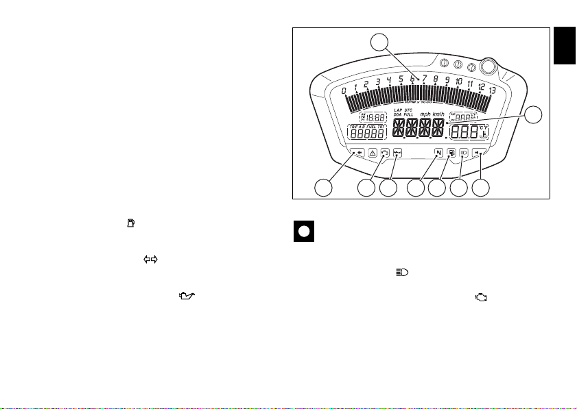
Instrument panel (Dashboard)
2
1
5 8 6 3 4 57
fig. 3
Instrument panel
1) LCD, (see page 13)
2) REVOLUTION COUNTER (rpm).
Indicates engine revs per minute.
3) Neutral light N
Illuminates when the gearbox is in neutral.
4) LOW FUEL LIGHT (YELLOW).
Comes on when fuel is low and there are about 3 litres of fuel
left in the tank.
5) TURN SIGNAL LIGHTS (GREEN).
Illuminates and flashes when the turn indicator is in
operation.
6) ENGINE OIL PRESSURE LIGHT (RED).
Illuminates when engine oil pressure is too low. It briefly
comes on when the ignition is switched to ON and normally
goes out a few seconds after engine starts.
It may come on briefly if the engine is very hot, but should go
out again as engine speed increases.
(GREEN).
Important
If this light (6) stays on, stop the engine to avoid
serious damage.
7) HIGH BEAM LIGHT (BLUE).
Illuminates when the high beam headlight is on.
8) “ENGINE DIAGNOSIS- EOBD” LIGHT (AMBER
YELLOW).
The engine ECU illuminates this light to indicate errors and
consequent engine lock.
E
11
Page 13
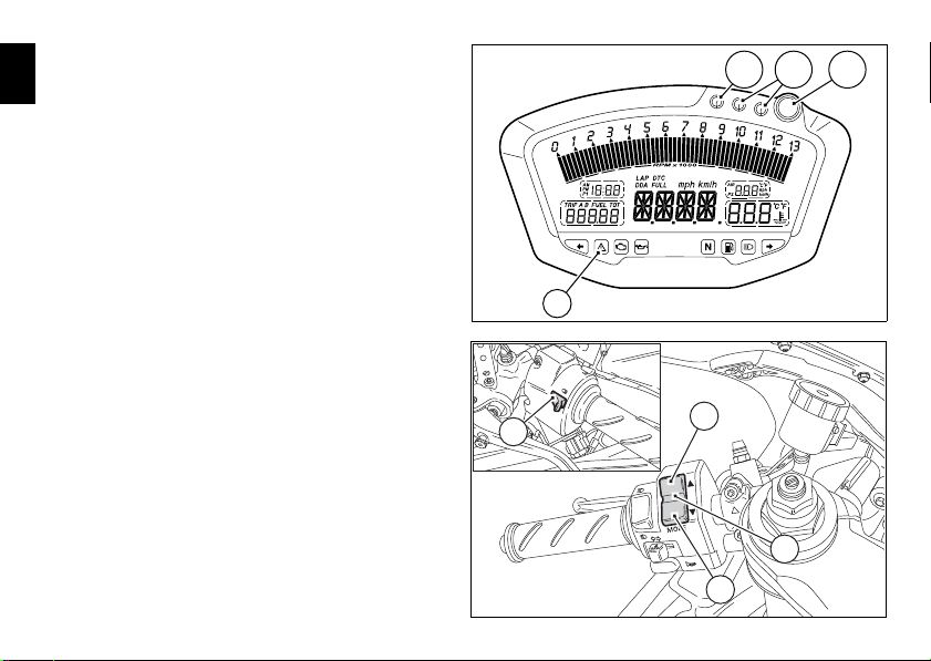
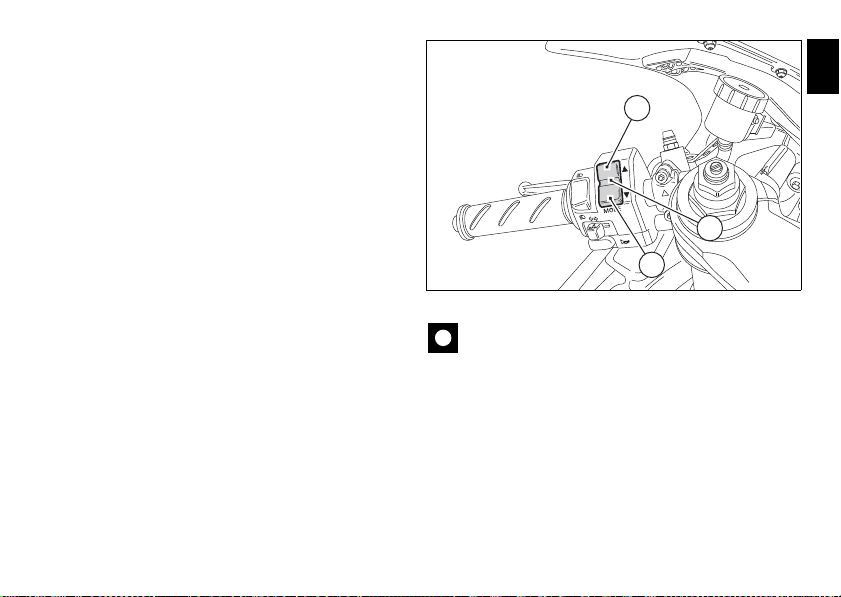
9) “VEHICLE DIAGNOSIS” LIGHT
9
10B 10C10A
fig. 4
A
12
B
11
fig. 5
Illuminates when the motorcycle diagnostics detects a
E
problem.
10) LIMITER LIGHT - OVER REV
Indicator light 10A: These lights come on steady at 800 rpm
below the limiter threshold.
Indicator lights 10A + 10B: These lights come on steady at
400 rpm below the limiter threshold.
Light 10A + 10B + 10C: they start flashing when the rev
limiter is reached.
11) CONTROL SWITCH
Button used to display and set instrument panel parameters.
It has two positions: A “▲“ and B “▼“.
12) HIGH-BEAM FLASH BUTTON FLASH (fig. 5)
The high-beam flash button may also be used to control the
LAP functions and the instrument panel DDA data logger.
12
Page 14
LCD unit functions
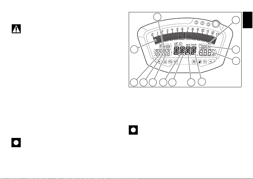
fig. 6
Warning
Any adjustments to the instrument panel must only be
carried out when the motorcycle is stationary. Never operate
the instrument panel controls while riding the motorcycle.
1) SPEEDOMETER.
Gives road speed
2) ODOMETER.
Shows total distance travelled.
3) TRIP METER.
Indicates distance covered since the meters (TRIP A and
TRIP B) were last reset.
4) TRIP FUEL METER.
Shows distance travelled on reserve fuel.
5) CLOCK.
6) LAP TIMER.
7) ENGINE RPM INDICATOR (RPM).
8) LAP TIME, MAXIMUM SPEED AND MAXIMUM RPM
RECORDING (LAP).
9) BATTERY VOLTAGE INDICATOR (BATT).
10) AIR TEMPERATURE INDICATOR.
11) WATER TEMPERATURE INDICATOR.
This function indicates engine coolant temperature.
Important
Stop riding if the temperature reaches the maximum
value, otherwise the engine might be damaged.
5
7
9
10
11
2 3 4
12) SERVICE WARNING (SERV).
The “SERV” message indicates that the vehicle has covered
the distance corresponding to a Scheduled Maintenance
interval. The message is displayed only at Key-On for 5
seconds. The service indicator will be reset at an authorised
Ducati Service Centre during servicing.
Important
The instrument panel incorporates diagnostic functions
for the electronic injection/ignition system. Never use the
menus reserved for trained personnel for any reason. If this
function is accidentally accessed, turn the key to OFF and
contact a Ducati Dealer or Authorised Service Centre for the
necessary checks.
1 6
12
8
E
13
Page 15
LCD – How to set/display parameters
ENGINE OFF
ENGINE OFF
ENGINE OFF ENGINE OFF
ENGINE OFF
ENGINE RUNNING
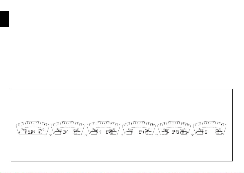
fig. 7
At key-on (key turned from OFF to ON) the instrument panel
E
activates all the digits of the LCD for 1 second and switches
on the indicator lights in sequence.
It then switches to “normal“ display mode showing the
model indication in place of the road speed readout and the
version (EU, UK, USA, CND, FRA, JAP) for 2 seconds.
Model is displayed as “scrolling“ text until the engine is
started.
14
Page 16
At Key-On, the instrument panel always shows the following
A
B
1
fig. 8
information (de-activating any previously activated
functions):
ODOMETER
AIR TEMPERATURE
CLOCK
SPEED
COOLANT TEMPERATURE
ENGINE RPM
With the switch (1, fig. 8) in position B “▼” the Odometer
readout (TOT) will cycle through the following functions:
TRIP A
TRIP B
TRIP FUEL (only if active)
until cycling back to the ODOMETER (TOT) function.
Pressing switch (1, fig.8) in position A “▲“ gives access to
the MENU and the following functions are displayed one
after another:
ERROR (only if at least one error is present)
BATT
RPM
LAP (OFF or ON)
LAP MEM
USB (OFF or ON)
ERASE USB
TIME SET
CODE (only if active)
Important
This menu is active only if the speed of the motorcycle
is less than 20 km/h. If this menu is open and the speed of
the motorcycle exceeds 20 km/h, the instrument panel
automatically exits the menu and returns to the initial display.
It is possible to exit the menu at any time, however, by
pressing switch (1, fig. 8) in position A “▲” for 3 seconds.
E
15
Page 17
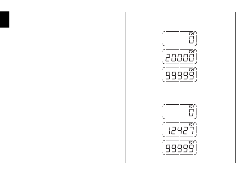
Total distance covered indicator:
fig. 9
EU, CND, FRA, JAP versions
UK, USA versions
“Odometer“
E
This function shows the total distance covered by the
vehicle.
This function shows the total distance covered by the
vehicle.
At Key-On the system automatically enters this function.
The odometer reading is stored permanently and cannot be
reset.
If the distance travelled exceeds 99999 km (or 99999 miles),
the value “99999” will be displayed permanently.
16
Page 18
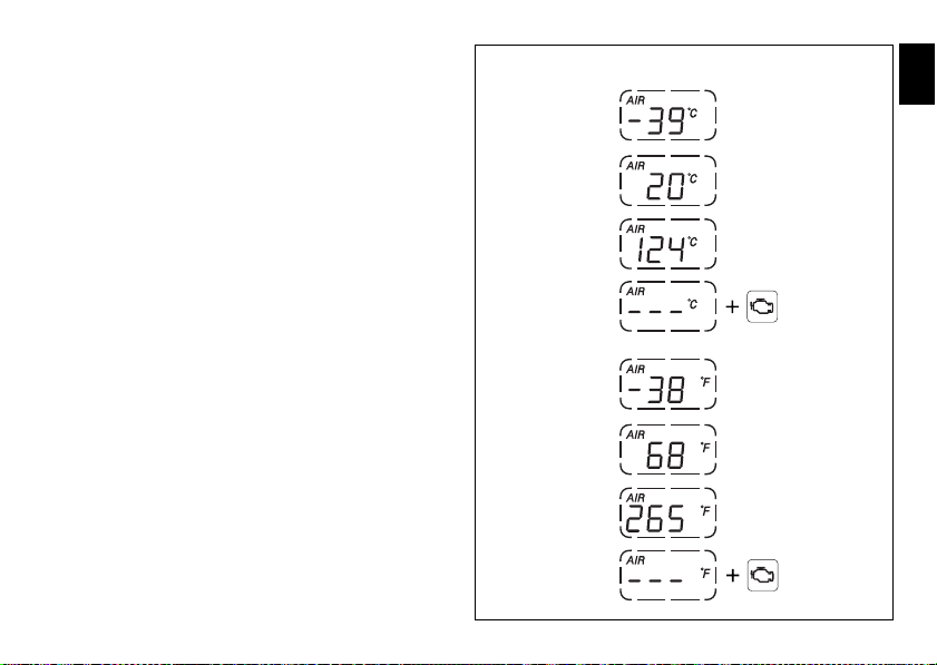
Air temperature indicator
fig. 10
Engine
Diagnosis
Engine
Diagnosis
EU, CND, FRA, JAP versions
UK, USA versions
This function shows the external temperature.
Display limits: -39°C ÷ +124°C
In the event of a sensor FAULT (-40°C,+125°C or
disconnected), a string of dashes “- - -“ (not flashing) is
displayed and the “Engine diagnosis - EOBD“ light comes on
(8, fig. 4).
E
17
Page 19
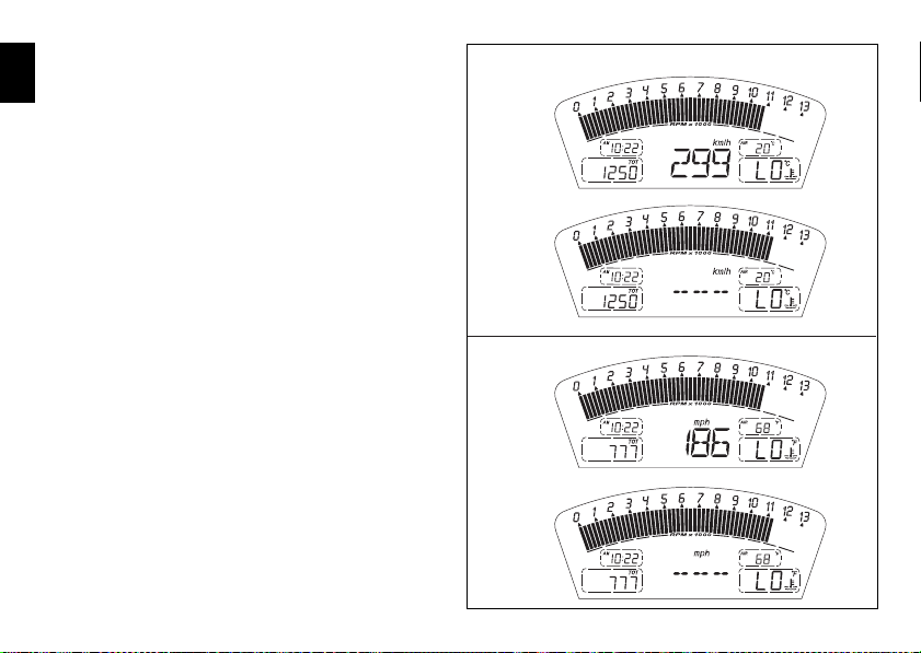
Vehicle speed indication
fig. 11
EU, CND, FRA, JAP versions
UK, USA versions
This function shows vehicle speed.
E
The instrument panel receives the actual speed value
(expressed in km/h) from the ECU and displays the value
increased by 8%.
Maximum speed displayed is 299 km/h (186 mph).
Over 299 km/h (186 mph) the display will show a series of
dashes “- - -“ (steadily lit - not flashing).
18
Page 20
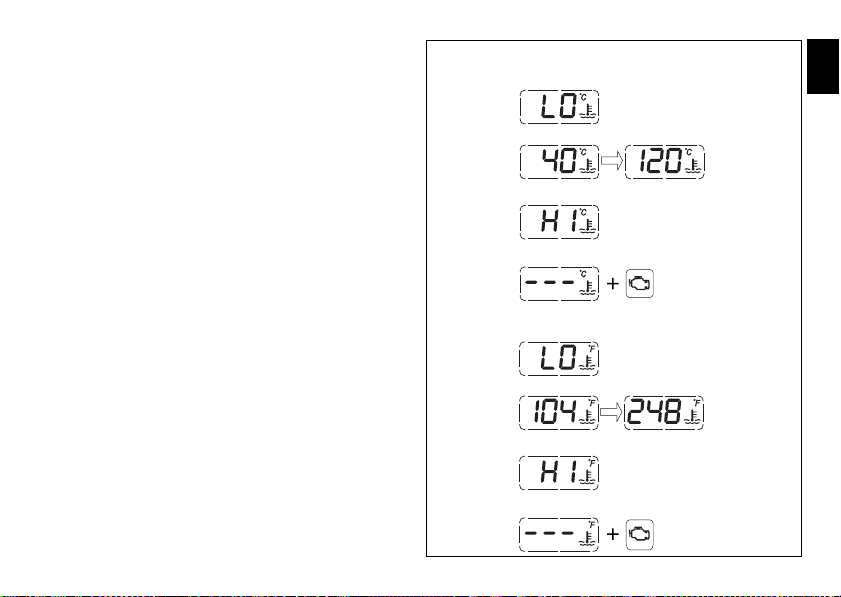
Engine coolant temperature indicator
fig. 12
Engine
Diagnosis
STEADY READING
STEADY READING
STEADY READING
FLASHING DATUM
FLASHING DATUM
STEADY READING
STEADY READING
STEADY READING
FLASHING DATUM
FLASHING DATUM
Engine
Diagnosis
EU, CND, FRA, JAP versions
UK, USA versions
It shows engine coolant temperature:
- If reading is -40 °C (-40 °F) or less, the display shows a
string of flashing dashes (“- - -“) and the “Engine
diagnosis - EOBD“ light (8, fig. 4) comes on;
- if reading is between -39 °C (-38 °F) and +39 °C (+102 °F),
the word “LO“ comes on steady on the display;
- if reading is between +40 °C (+104 °F) and +120 °C
(+248 °F), the display shows temperature reading (on
steady);
- if reading is between +121 °C (+250 °F) and +124 °C
(+255 °F), the word “HI“ is shown flashing on the
display;
- if reading is +125 °C (+257 °F) or higher, the display
shows a string of flashing dashes (“- - -“) and the “Engine
diagnosis - EOBD“ light (9, fig. 4) comes on.
- In the event of a sensor FAULT, a string of flashing
dashes (“- - -“) is shown and the “Engine diagnosis EOBD“ light (8, fig. 4) comes on.
E
19
Page 21

Trip meter “TRIP A”
fig. 13
EU, CND, FRA, JAP versions
UK, USA versions
This function shows the distance travelled since the Trip
E
meter was last reset.
Holding button (1, fig.8) pressed in position B “▼“ for 3
seconds when this function is displayed resets the trip
meter.
If the reading exceeds 999.9, it is reset to zero and the count
restarts automatically.
20
Page 22
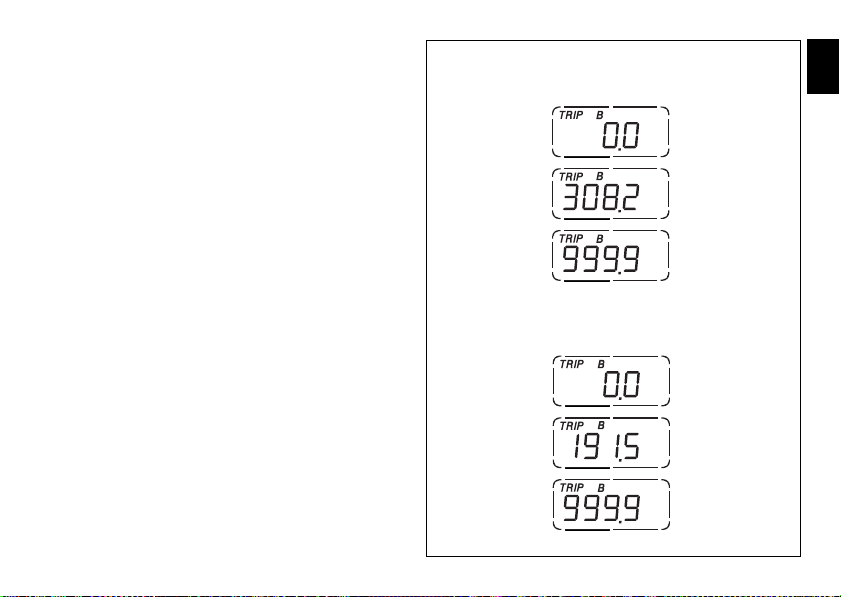
Trip meter “TRIP B”
fig. 14
EU, CND, FRA, JAP versions
UK, USA versions
This function shows the distance travelled since the Trip
meter was last reset.
Holding button (1, fig.8) pressed in position B “▼“ for 3
seconds when this function is displayed resets the trip
meter.
If the reading exceeds 999.9, it is reset to zero and the count
restarts automatically.
E
21
Page 23
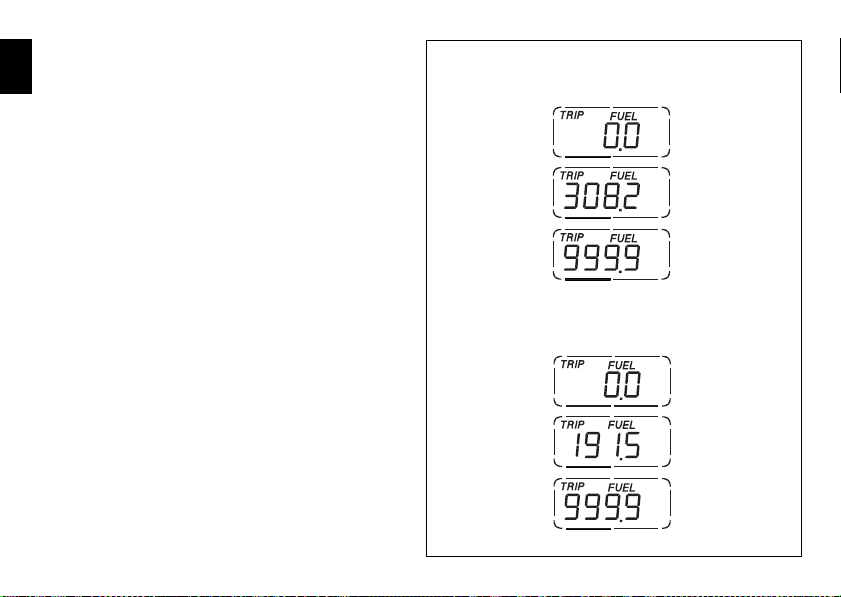
Distance travelled on fuel reserve: “TRIP
fig. 15
EU, CND, FRA, JAP versions
UK, USA versions
FUEL“
E
This function shows the distance travelled on fuel reserve.
When the fuel warning light comes on, the TRIP FUEL meter
is activated automatically, regardless of the function
displayed. If the fuel level remains in reserve, the reading is
saved even after Key-Off.
The count stops automatically when the fuel level rises
above reserve.
If the reading exceeds 999.9, it is reset and the count restarts
automatically.
22
Page 24
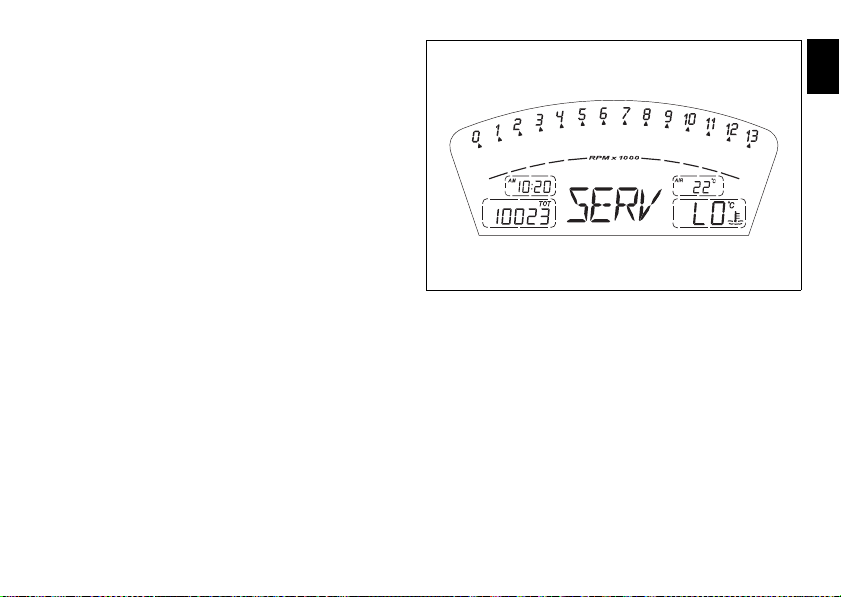
Service indicator (SERV)
fig. 16
It shows service intervals (service).
The message “SERV” is displayed at the following intervals:
after the first 1000 km on the odometer;
every 12000 km on the odometer.
The information is displayed only at Key-On for 5 seconds.
When the service indicator appears, contact your Ducati
dealer or Authorised Service Centre.
E
23
Page 25
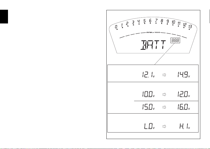
Battery voltage indicator (BATT)
STATUS 1
STATUS 2
STATUS 3
FIXED FIXED
FLASHING FLASHING
FLASHING FLASHING
fig. 17
This function provides battery voltage indication.
E
To display this function, go into the menu and select the
“BATT” page.
The battery voltage reading is displayed as follows:
- if voltage is between 12.1 and 14.9 Volt, the reading is on
steady;
- if voltage is between 10.0 and 12.0 Volt or between 15.0
and 16.0 Volt, the reading will be flashing;
- if voltage is 9.9 Volt or less, the word “LO“ is shown
flashing and the “Vehicle diagnosis“ light (9, fig.4) comes
on;
- if voltage is 16.1 Volt or higher, the word “HI“ is shown
flashing and the “Vehicle diagnosis“ light (9, fig. 4)
comes on.
24
Page 26
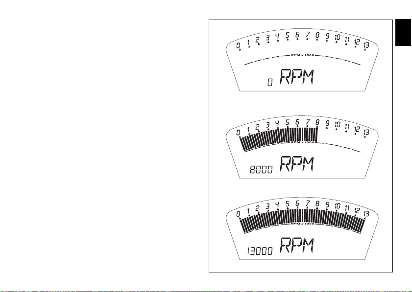
Engine idle RPM setting (RPM)
fig. 18
This function describes engine idle setup.
To display the function, go into the menu and call up the
“RPM” page.
In addition to the upper rev counter scale, the display also
shows engine rpm numerically so that you can adjust the idle
speed more precisely.
E
25
Page 27
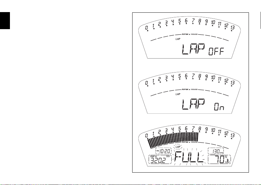
LAP time display function
fig. 19
This function lets you display lap times.
E
To enable this function, enter the menu and set the “LAP“
function to “On“ by holding switch (1, fig. 8) pressed in
position B “▼“ for 3 seconds.
The lap timer is started and stopped using the high-beam
flasher button FLASH (12, fig. 5) on the LH switch.
When the LAP function is active, each time you press the
FLASH button, the display will show the lap time for 10
seconds, before reverting to normal mode.
You can save a maximum of 30 laps in the memory.
If the memory is full, each time you press the FLASH button,
no more lap times can be saved and the display will show the
flashing message “FULL” for 3 seconds until the memory is
reset.
26
Page 28
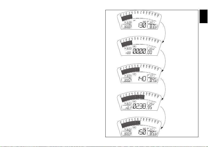
When the LAP function is set to Off in the menu, the current
fig. 20
Press Flash
After 10 secs.
Press Flash
After 10 secs.
“lap“ is not stored.
If the LAP function is active and the display is suddenly
switched off (Key-Off), the LAP function is switched off
automatically (even if the timer was ON, the lap in progress
is not saved).
If the timer is not stopped, when it reaches 99 minutes, 59
seconds and 99 hundredths, it restarts from 0 (zero) and
continues until the function is switched off.
If however the LAP function is switched on and the memory
has not been cleared, but fewer than 30 laps have been
saved (e.g. 18 laps), the display will store any remaining laps
until the memory is full (in this case, it will store an additional
12 laps).
This function only displays lap times once; but other data are
also saved (MAX speed, MAX rpm, rev limiter if reached) for
viewing at a later date in the Lap Memory function.
E
27
Page 29
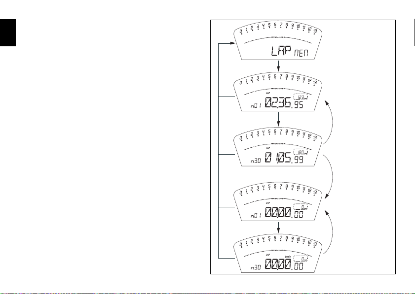
Stored data display (LAP Memory)
A
B
B
A
A
A
B
B x 19
B x 19
fig. 21
B = ON for 3 secs.
Resets lap times
in memory
Displays the data saved using the LAP function: lap time,
E
MAX speed and MAX rpm.
To display the saved lap times, go into the menu and select
the “LAP MEM” page.
Holding switch (1, fig. 8) pressed in position B “▼“ for 3
seconds in this menu page accesses the “1st lap“ view
mode. The display will show the lap number, lap time, MAX
speed and the MAX rpm reached for the lap in question.
Press switch (1, fig. 8) in position B “▼“ repeatedly to scroll
through the 30 laps stored until returning to the 1st lap.
If you press switch (1, fig. 8) in position B “▼“ for 3 seconds
while the saved times are displayed, the display immediately
resets all the saved times; In this case, if the LAP function
was active, it is switched off automatically.
The MAX speed saved is the maximum speed indicated on
the display in Lap function.
If MAX speed reading exceeds 299 Km/h (186 mph) while
the information is stored, speed reading is displayed
(example: 316 Km/h).
If there is no reading in the memory, the 30 times are shown,
with the display showing “00.00.00”, MAX rpm = 0 and
MAX speed = 0.
If the engine reached one of the two thresholds before the
limiter or the limiter threshold during a lap, the corresponding
lights (10, fig. 4) come on while viewing stored lap times.
28
Page 30
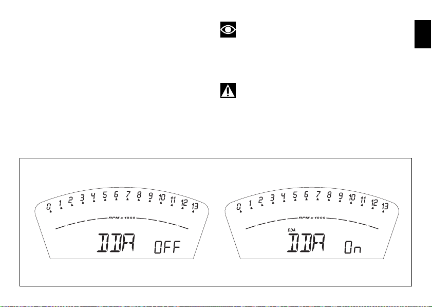
DDA data acquisition
fig. 22
This function activates the DDA analyzer (not fitted for this
model, but available at Ducati selling network): the DDA
must be connected to the motorcycle wiring.
To enable this function, enter the menu and set “DDA“ data
logger to “On“ by holding switch (1, fig. 8) pressed in
position B “▼“ for 3 seconds.
The START/STOP control for the data logger lap separator is
the high-beam flasher button FLASH (12, fig. 5) on the LH
switch.
If the DDA function is active and the display is suddenly
switched off (Key-Off), the function is switched off
automatically.
Note
Online assistance is available to Ducati Data Analyzer
(DDA) owners (http://dda.prosa.com). This service will
provide anything necessary to correctly use the DDA with
your PC: both for the device and the software for analysing
the recorded data.
Warning
After use, disconnect the DDA from the main wiring
harness.
E
29
Page 31

Erase DDA
DDA = ON
fig. 23
Displayed for 2 secs.
Displayed for 10 secs.
Displayed for 2 secs.
B = On for 3 secs.
YES
NO
This function enables you to delete the data saved on the
E
DDA (not fitted for this model, but available in all Ducati
selling network): the DDA must be connected to the
motorcycle wiring.
To delete the data, enter the menu and select the “Erase
DDA” page.
If you press switch (1, fig. 8) in position B “▼“ for 3 seconds
and the DDA is not acquiring data, the message “WAIT…” is
shown on the display for 10 seconds. After 10 seconds, the
message “ERASE OK” appears for 2 seconds, to confirm
that the data have been deleted.
If switch (1, fig. 8) is pressed in the B “▼“ position for 3
seconds while the DDA data logger is acquiring data, the data
logger memory is not erased and the display shows message
“FAIL“ for 2 seconds.
30
Page 32

Clock setting function
fig. 24
B = ON for 3 secs.
Flashing
Flashing
Flashing
Flashing
Flashing
Flashing
This function is used to set the clock time.
To set the clock, select the “TIME Set” page from the menu.
Holding switch (1, fig. 8) pressed in position B “▼“ for 3
seconds in this menu page gives access to the setup mode.
On entering this function, the message “AM” flashes on the
display; if you press switch (1, fig. 8) in position B “▼” the
message “PM” flashes; if you press switch (1, fig. 8) in
position B “▼” mode will go back to previous setting (if it is
00:00, when toggling from “AM” to “PM”, 12:00 will be
displayed).
Pressing switch (1, fig. 8) in position A “▲“ gives access to
the hour setting mode; hours start to flash. Each time you
press the button in position B “▼“, the digit will increase by
one hour. If the switch is held pressed in position B “▼” the
number increases cyclically in steps of one hour every
second (when the switch is held depressed, the hours do not
flash).
Pressing switch (1, fig. 8) in position A “▲“ gives access to
the minutes setting mode; minutes start to flash. Each time
you press the button in position B “▼“, the digit will increase
by one minute. If you hold the switch down in position B
“▼”, the count increases cyclically in steps of 1 minute every
second. If the button is held depressed in position B “▼“ for
over 5 seconds, minutes will increase by 1 minute every
100ms (while the button is held depressed in position B “▼“,
seconds will not flash).
Pressing the button in position A “▲“, exits setup mode and
the new time is displayed.
E
B
B
B
B
B
B
A
A
A
A
A
A
31
Page 33

Instrument panel diagnostics
E
Important
The instrument runs the system diagnostics correctly
60 seconds after the last Key-Off.
Any abnormal vehicle behaviour is displayed.
If more errors are present, they are displayed one by one
every 3 seconds.
Possible errors are listed in the table below.
WARNING LIGHT ERROR MESSAGE ERROR
COIL 8.1 Horizontal cylinder coil error
COIL 8.2 Horizontal cylinder coil error
COIL 9.1 Vertical cylinder coil error
COIL 9.2 Vertical cylinder coil error
COIL 10.1 Horizontal cylinder coil error
COIL 10.2 Horizontal cylinder coil error
COIL 11.1 Vertical cylinder coil error
32
Warning
When an error is displayed, always contact a Ducati
Dealer or authorised Service Center.
Page 34

WARNING LIGHT ERROR MESSAGE ERROR
COIL 11.2 Vertical cylinder coil error
INJE 12.1 Horizontal cylinder injector error
INJE 12.2 Horizontal cylinder injector error
INJE 13.1 Vertical cylinder injector error
INJE 13.2 Vertical cylinder injector error
INJE 14.1 Horizontal cylinder injector error
INJE 14.2 Horizontal cylinder injector error
INJE 15.1 Vertical cylinder injector error
INJE 15.2 Vertical cylinder injector error
PUMP 16.0 Fuel pump relay error
FAN 18.1 Fan relay error
FAN 18.2 Fan relay error
E
33
Page 35

WARNING LIGHT ERROR MESSAGE ERROR
E
STRT 19.1 Solenoid starter error
STRT 19.2 Solenoid starter error
STEP. 21.1 Stepper motor error
STEP. 21.2 Stepper motor error
STEP. 21.3 Stepper motor error
LAMB. 22.1 Lambda heaters error
LAMB. 22.2 Lambda heaters error
EXVL 23.1 Exhaust butterfly valve motor error
EXVL 23.2 Exhaust butterfly valve motor error
EXVL 23.3 Exhaust butterfly valve motor error
EXVL 23.4 Exhaust butterfly valve motor error
TPS 1.1 Throttle position sensor error
34
Page 36

WARNING LIGHT ERROR MESSAGE ERROR
TPS 1.2 Throttle position sensor error
PRESS 2.1 Pressure sensor error
PRESS 2.2 Pressure sensor error
T.WAT 3.1 Engine water temperature sensor error
T.WAT 3.2 Engine water temperature sensor error
AIR 4.1 Air temperature sensor error
AIR 4.2 Air temperature sensor error
BATT 5.1 Battery voltage error
BATT 5.2 Battery voltage error
LAMB 6.1 Lambda sensor error
TILT 6.2 Lambda sensor error 2
DTC 8.0 Traction control ECU error
E
35
Page 37

WARNING LIGHT ERROR MESSAGE ERROR
E
ECU 30.0 Engine Control Unit error
PK.UP 34.0 Pick-up sensor error
SPEE. 36.0 Speed sensor error
IMMO 37.0 Immobilizer error
IMMO 37.1 Immobilizer error
IMMO 37.3 Immobilizer error
IMMO 37.5 Immobilizer error
CAN 38.0 CAN communication line error
36
Page 38

Instrument panel backlighting
The instrument panel backlighting is always activated by KeyOn.
The instrument panel is equipped with sensors that detect
the ambient light level and at night reduce the maximum
backlighting level by 20% to prevent glare.
Headlight “smart” auto-off
This function helps reduce battery use by automatically
switching off the headlight. The device is triggered in 3
cases:
- 1) When the key is turned from OFF to ON and the
engine is not started within 60 seconds, the headlight is
turned off and will be turned back on next time you start
the engine.
- 2) After the vehicle has been running with the headlights
on and the engine is stopped using the RUN-STOP button
on the RH switch.
In this case, 60 seconds after stopping the engine, the
headlight is turned off and will be turned back on next
time you start the engine.
- 3) While starting up the engine, the headlight is turned off
and back on as soon as the engine is started.
Headlight “smart” SWITCH-ON
This function allows programmed activation of the headlight
even with the motorcycle off (Key-Off).
The instrument panel stays active for 60 seconds soon after
Key-Off, and the headlight can be switched on by pressing
switch (1, fig. 8) in position B “▼“.
During these 60 seconds, each time switch (1, fig. 8) is
pressed in position B “▼”, the instrument panel will activate
the headlight for 30 seconds; each press will add to the
headlight activation time, up to a maximum of 6 presses of
switch (1, fig. 8) in position B “▼” (maximum activation time
of 180 seconds).
After the first time you press switch (1, fig. 8) in position B
“▼”, the period of 30 seconds starts, thus switching on the
headlight. Further switch-on time can be added only if you
press the switch again within these 30 seconds. If the 30
seconds have elapsed, no further multiples of 30 seconds
can be added, and the instrument panel will switch off the
headlight.
To reset this function, you must perform at least one Key-On/
Key-Off.
If the battery power is interrupted at any time while this
function is active, when power is restored, the instrument
panel will de-activate the function (the instrument panel does
not remain active for 60 seconds).
E
37
Page 39

The immobilizer system
B
1
fig. 25
For additional anti-theft protection, the motorcycle is
E
equipped with an IMMOBILIZER, an electronic system that
locks the engine automatically whenever the ignition switch
is turned off.
The grip of each ignition key contains an electronic device
that modulates the output signal from a special antenna in
the switch when the ignition is switched On. The modulated
signal represents the “password” (which is changed at each
start-up) by which the ECU recognizes the ignition key. The
ECU will only allow the engine to start if it recognises this
password.
Keys (fig. 25)
The owner receives a set of keys, comprising:
- 2 (BLACK) keys B
These contain the “code” of the immobilizer system.
Note
Your Ducati dealer may ask you to produce your Code
Card in order to carry out certain servicing operations.
The black keys (B) are the keys for normal use, and are used
to:
- start up the engine
- open the fuel tank filler plug.
- open the seat lock.
Note
The two keys have a small tag (1) attached, which
shows their identification number.
Warning
Keep the keys separate, and store the tag (1) in a safe
place.
It is also advisable to use only one of the black keys to start
the motorcycle.
38
Page 40

Code card
fig. 26
A
fig. 27
The CODE CARD (fig. 26) supplied with the keys reports an
electronic code (A, fig. 27) to start the engine in the event it
fails to start after KEY-ON because the immobilizer system
inhibited the ignition.
Warning
Keep the CODE CARD in a safe place. However, it is
advisable to keep the electronic code printed on the CODE
CARD handy when you ride your motorcycle, in case it is
necessary to enable the engine through the procedure
described below. This procedure lets you disable the
“engine block” function - indicated by the amber yellow
Vehicle diagnosis light (9, fig. 3) coming on - in the event of
problems with the immobilizer system.
This operation is only possible if the electronic code indicated
on the code card is known.
Warning
Your dealer will ask you to produce the Code Card in
order to re-program or replace a key.
E
39
Page 41

Immobilizer override procedure
A
A
A
A
A
B
B
B
B
B
B
B
B
B
fig. 28
B = ON for 3 secs.
Code OK?
No
Yes
Should the immobilizer become locked, you can perform the
E
“Immobilizer Override” procedure from the instrument panel
by entering the respective function as described below.
Enter the menu and go to page “CODE“.
Note
This menu should be active only if there is at least one
immobilizer error.
With this page selected, the initial code is always displayed
as “00000”. If you hold pressed switch (1, fig. 8) in position
B “▼“ for 3 seconds, you will access the procedure for
entering the electronic code given on the Code Card.
40
Page 42

Entering the code:
on entering this function, the first digit on the left starts
flashing.
Button (1, fig. 8):
each time you press the switch in position B “▼”, the
number increases cyclically in steps of one digit every
second;
if you press the button in position A “▲“, you will move to
the second digit, which will start to flash. Each time you
press the switch in position B “▼”, the number increases
cyclically in steps of one digit every second;
if you press the switch in position A “▲”, you can set the
third digit, which will start flashing. Each time you press the
switch in position B “▼”, the number increases cyclically in
steps of one digit every second;
if you press the button in position A “▲“, you will move to
the fourth digit, which will start to flash. Each time you press
the switch in position B “▼”, the number increases cyclically
in steps of one digit every second;
if you press the switch in position A “▲”, you can set the
fifth digit, which will start flashing. Each time you press the
switch in position B “▼”, the number increases cyclically in
steps of one digit every second;
press in position A “▲” to confirm the code.
If the code has been entered correctly, the message CODE
and the code itself will flash simultaneously for 4 seconds.
The “Vehicle diagnosis“ light (9, fig. 4) will turn off; The
instrument panel then automatically exits the menu, thus
allowing “temporary” starting of the motorcycle.
If the error persists, at the next key-on, the instrument panel
will return to an error state and immobilize the engine.
If the code is not entered correctly, the instrument panel
reverts to the “CODE“ menu and display the default
“00000“ code.
E
41
Page 43

Operation
When the ignition key is turned from ON to OFF, the
E
immobilizer system activates the engine lock. When the
ignition key is turned from OFF to ON to start the engine:
1) if the code is recognised, the protection system releases
the engine lock. Press the START button (2, fig. 34), to start
the engine;
2) if the “Vehicle diagnosis“ light (9, fig. 4) comes on and the
page with the message “Error IMMO“ is displayed when
you press switch (1, fig. 8) in position “▼“, it means that the
code was not recognised. In this case, turn the ignition key
back to OFF and then to ON again. If the engine still does not
start, try again with the other black key. If the engine still
does not start, contact the DUCATI Service network.
Warning
Sharp knocks can damage the electronic components
inside the key.
Always use the same key throughout the procedure. Failure
to do so might prevent the system from recognising the code
of the key in use.
42
Duplicate keys
If you need additional keys, contact your DUCATI Service
Centre with all the keys you have in your possession and
your CODE CARD.
The Ducati Service Centre will program all the new keys as
well as any keys you already have.
You may be asked to provide proof that you are the
legitimate owner of the motorcycle.
The codes of any keys not submitted will be wiped off from
the memory to make those keys unserviceable in case they
have been lost.
Note
If you sell your motorcycle, do not forget to give all
keys and the CODE CARD to the new owner.
Page 44

Service menu - units of measurement
(UNIT SET)
This function allows you to set the units of measurement for
the values displayed on the instrument panel.
To enter the menu service push button (1, fig. 8) in position
A “▲“ while turning the key from “Off“ to “On“
Note
Within this menu, any other function is disabled and
engine starting is disabled as well.
The first function displayed is the “Immobilizer
Reprogramming” procedure (REPR Code), pressing the
button (1, fig. 8) in the position A “▲” or B “▼” select the
“Setting Special” (Set UNIT) function.
Now press the button (1, fig. 8) in the position B “▼” for
3 seconds.
Each time you press switch (1, fig. 8) “▼” in the position B
“▼”, the instrument panel scrolls through the following
sequence of options, which flash on the display:
UNIT OF MEASUREMENT
Country
standard
EU Km/h °C Km
EN Mph °C miles
USA Mph °F miles
CND Km/h °C Km
FRA Km/h °C Km
JAP Km/h °C Km
ECU ld. The instrument panel sets units of
If you press the button (1, fig. 8) in position B “▼“ for
3 seconds, the option currently displayed will be saved to
memory and the word “MEM” will appear.
Upon the following Key-On the instrument panel will be set
to the new settings.
Speed Air
measurement according to ECU
information
temperature
Odometer/
trip meters
E
43
Page 45

E
fig. 29
Key OFF to quit
Press B for 3 s
Press B for 3 s
Press B
Press A
Press A
Press B
Press A
Press A
Press A
Press A
Press B for 3 s
Press B for 3 s
Press B for 3 s
Press B for 3 s
Press B for 3 s
Press B
Press B
Press B
Press B
44
Page 46

Controls
1
4
3
2
9
8
5
7
6
fig. 30
E
Warning
This section shows the position and function of the
controls used to ride the motorcycle. Be sure to read this
information carefully before you use the controls.
Position of motorcycle controls (fig. 30)
1) Instrument panel.
2) Key-operated ignition switch and steering lock.
3) Left-hand handlebar switch.
4) Clutch lever.
5) Rear brake pedal.
6) Right-hand handlebar switch.
7) Throttle twistgrip.
8) Front brake lever.
9) Gear change pedal.
45
Page 47

Key-operated ignition switch and steering
A
B
C
D
fig. 31
lock
E
(fig. 31)
This is located in front of the fuel tank and has four positions:
A) ON:enables lights and engine operation;
B) OFF: disables lights and engine operation;
C) LOCK:the steering is locked;
D) P: parking light on and steering locked.
Note
To move the key to the latter two positions, push it in
before turning. The key can be removed in positions (B), (C)
and (D).
46
Page 48

LH switch (fig. 32)
1 2
4
3 5
fig. 32
1) Dip switch, two-position light selector switch:
position = low beam on;
position = high beam on.
2) Switch = 3-position turn indicator:
centre position = off;
position = left turn;
position = right turn.
To cancel turn indicators, push in once switch returns to
central position.
3) Button = warning horn.
4) Button = high-beam flasher (FLASH) and instrument
panel control.
5) Two-position instrument panel control switch:
position “▲”;
position “▼”.
E
47
Page 49

Clutch lever
2 1
fig. 33
Lever (1) disengages the clutch. It features a dial adjuster (2)
E
for lever distance from the twistgrip on semihandlebar.
The lever distance can be adjusted through 10 clicks of the
dial (2). Turn clockwise to increase lever distance from the
twistgrip. Turn the adjuster counter clockwise to decrease
lever distance.
When the clutch lever (1) is operated, drive from the engine
to the gearbox and the rear wheel is disengaged. Correct use
of the clutch lever is very important in all riding situations,
especially when moving off.
Warning
Any adjustment of clutch lever must be carried out
when motorcycle is stationary.
Important
Using the clutch properly will prolong the life of the
engine and prevent any damage to components in the
transmission.
Note
It is possible to start the engine with the side stand
down and the gearbox in neutral. When starting the bike with
a gear engaged, pull the clutch lever (in this case the side
stand must be up).
48
Page 50

RH switch (fig. 34)
3
1
2
fig. 34
1) ENGINE STOP switch, two positions:
position (RUN) = run.
position (OFF) = stop.
Warning
This switch is mainly intended for use in emergencies
when you need to stop the engine quickly. After stopping the
engine, return the switch to the position to enable
starting.
Important
Stopping the engine using switch (1) after riding with
the lights on and leaving the ignition key in the ON position,
may run the battery flat as the lights will remain on.
2) Button = engine start
Throttle twistgrip (fig. 34)
The twistgrip (3) on the right-hand semihandlebar opens the
throttles. When released, it will spring back to the initial
position (idling speed).
E
49
Page 51

Front brake lever (fig. 35)
21
fig. 35
Pull in the lever (1) towards the twistgrip to operate the front
E
brake. The system is hydraulically operated and you just need
to pull the lever gently.
The brake lever (1) has a dial (2) for adjusting the distance
between lever and twistgrip on the semihandlebar.
The lever distance can be adjusted through 10 clicks of the
dial (2). Turn clockwise to increase lever distance from the
twistgrip. Turn the adjuster counter clockwise to decrease
lever distance.
50
Page 52

Rear brake pedal (fig. 36)
1
fig. 36
6
5
4
3
2
1
N
fig. 37
Push down on the pedal (1) with your foot to operate the rear
brake.
The system is controlled hydraulically.
Gear change pedal (fig. 37)
When released, the gear change pedal automatically returns
to rest position N in the centre; This is indicated by the
instrument panel light N (3, fig. 3) coming on.
The pedal can be moved:
down = press down the pedal to engage the 1
shift down. The N light will go out.
upwards= lift the pedal to engage 2
th
and 6th gears.
5
Each time you move the pedal you will engage the next gear.
nd
st
gear and to
gear and then 3rd, 4th,
E
51
Page 53

Setting the gear change and rear brake
2 1 3
fig. 38
pedals
E
52
(fig. 38 and fig. 39)
The position of the gearchange and rear brake pedals in
relation to the footrests can be adjusted to suit the
requirements of the rider.
To adjust the position, proceed as follows:
hold the rod (1) and loosen lock nuts (2) and (3).
Note
The locknut (2) has a left-hand thread.
Fit an open-end wrench to hexagonal element of linkage (1)
and rotate until setting pedal in the desired position.
Tighten both check nuts onto linkage.
Page 54

To set the rear brake pedal,
7
4
5
6
fig. 39
loosen counter nut (4).
Turn the pedal travel adjustment screw (5) until the pedal is
in the desired position.
Tighten the check nut (4) to 2.3 Nm.
Work pedal by hand to make sure it has 1.5 - 2 mm free play
before brake begins to bite.
If not so, set the length of cylinder linkage as follows.
Loosen the check nut (6) on cylinder linkage.
Tighten linkage into fork (7) to increase play, or unscrew
linkage to reduce it.
Tighten the check nut (6) to 7.5 Nm and check play again.
E
53
Page 55

Main components and
3
4
15
6
5 2
8
6
7
9
fig. 40
E
devices
Position on the vehicle (fig. 40)
1) Tank filler plug.
2) Seat lock.
3) Side stand.
4) Steering damper.
5) Rear-view mirrors.
6) Front fork adjusters.
7) Rear shock absorber adjusters.
8) Exhaust silencer (see “Warning” on page 69).
9) Catalytic converter.
54
Page 56

Fuel tank plug (fig. 41)
1
fig. 41
Opening
Raise the cover (1) and insert the key into the lock. Give the
key a 1/4 turn clockwise to unlock.
Lift the cap.
Closing
Refit the plug with the key in it and push it down into its seat.
Turn the key anticlockwise to the initial position and remove
it. Replace the lock cover (1).
Note
The cap can only be closed with the key inserted.
Warning
Always make sure you have properly refitted (see page
70) and closed the plug after each refuelling.
E
55
Page 57

Seat lock
2
1
1
1
0
0
fig. 42
3
4
5
fig. 43
E
Opening (fig. 42)
Insert the key into the seat lock (1) and turn it clockwise until
the seat catch disengages with an audible click.
Raise the rear of the seat (2) until it can be extracted.
Closing (fig. 43)
Insert the hooks (3) on the base of the seat under the rear
subframe.
Push the passenger seat rear end until pin (4) clicks in place
inside latch (5).
Pull the passenger seat moderately upwards to make sure it
is correctly and firmly engaged.
56
Page 58

Side stand (fig. 44)
2
1
fig. 44
Important
Before lowering the side stand, make sure that the
bearing surface is hard and flat.
Do not park on soft or pebbled ground or on asphalt melt by
the sun heat and similar or the motorcycle may fall over.
When parking on a slope, always park with the rear wheel on
the downhill side.
To lower the side stand, hold the motorcycle handlebars with
both hands and, with your foot, push down the stand (1) until
fully extended. Tilt the motorcycle until the sidestand is
resting on the ground.
Warning
Do not sit on the motorcycle when it is supported on
the sidestand.
To raise the sidestand to rest position (horizontal), tilt the
motorcycle to the right and, at the same time, lift the stand
(1) with your foot.
Note
Check for proper operation of the stand mechanism
(two springs, one into the other) and the safety sensor (2) at
regular intervals.
Note
The engine can be started with the sidestand down
and the gearbox in neutral. If starting with a gear engaged,
pull in the clutch lever (in this case the sidestand must be up).
E
57
Page 59

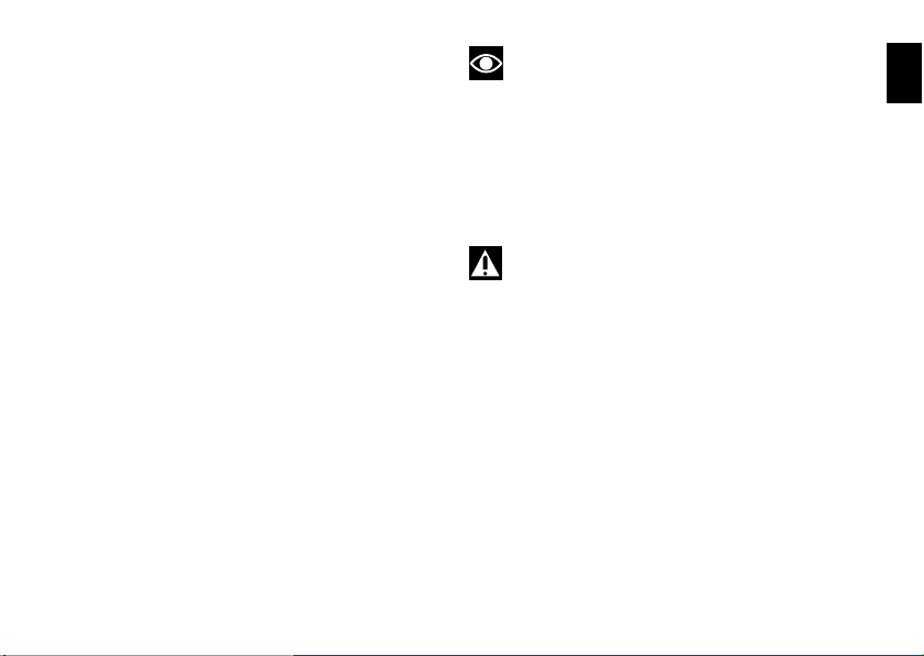
Steering damper (fig. 45)
fig. 45
It is located up front before the tank and is secured to frame
E
and steering head.
It provides stable and accurate steering, improving the
motorcycle's handling response under any conditions.
58
Page 60

Front fork adjusters
1
A
2
fig. 46
The front fork used on this motorcycle has rebound,
compression and spring preload adjustment.
This adjustment is done using the outer adjusters:
1) to adjust rebound damping (fig. 46);
2) to adjust spring preload (fig. 46);
3) to adjust compression damping (fig. 47).
Park the motorcycle in a stable position on its side stand.
Turn the adjuster (1) on every fork leg top with a suitable
wrench to adjust rebound damping.
As you turn the adjusting screws (1 and 3), you will hear
them click. Each click identifies a setting. The stiffest
damping setting is obtained with the adjuster turned fully
clockwise to the “0” position. Start with this position and
turn anticlockwise. Count the clicks, which correspond to
position 1, 2 and so forth.
E
59
Page 61

STANDARD factory setting is as follows:
3
fig. 47
Compression:
E
3/4 laps;
Rebound:
12 clicks.
Spring preload: (A, fig. 46): 18 mm;
To change the preload of the spring inside each fork leg, turn
the hex. adjuster (2, fig. 46) with a 22-mm hexagon wrench.
Important
Adjust both fork legs to same settings.
60
Page 62

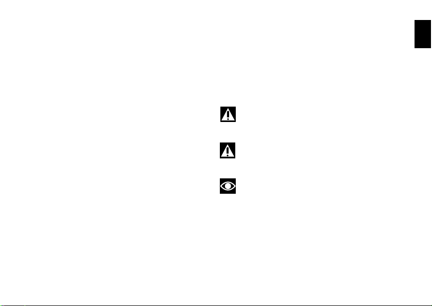
Rear shock absorber adjusters (fig. 48)
2
3
1
fig. 48
The rear shock absorber has outer adjusters that enable you
to adjust your motorcycle to the load.
The adjuster (1) on the left side of the connection holding the
shock absorber to the swinging arm controls rebound
damping.
The adjuster (2) on the shock absorber expansion reservoir
controls compression damping.
Turning the adjusters (1 and 2) clockwise gives harder
damping, turning anticlockwise gives softer damping.
STANDARD setting:
from fully closed (clockwise) loosen:
shim (1) by 2 laps
shim (2) by 2 laps
Spring preload: 20 mm.
Two ring nuts (3) located on the top section of the shock
absorber are used to adjust the outer spring preload. To
change spring preload, slacken off the upper lock nut. Then
TIGHTEN or SLACKEN the lower ring nut to INCREASE or
DECREASE spring preload.
E
61
Page 63

Once preload has been set as required, tighten the upper ring
nut.
E
Warning
Use a pin wrench to turn the preload adjusting ring nut.
Take special care when turning the ring nut, to avoid injuring
your hand by striking it violently against other parts of the
motorcycle if the wrench suddenly slips off the nut while
turning.
Warning
The shock absorber is filled with gas under pressure
and may cause severe damage if taken apart by unskilled
persons.
When carrying a passenger and luggage, set the rear shock
absorber spring to proper preload to improve motorcycle
handling and keep safe clearance from the ground. You may
find that rebound damping needs adjusting as well.
62
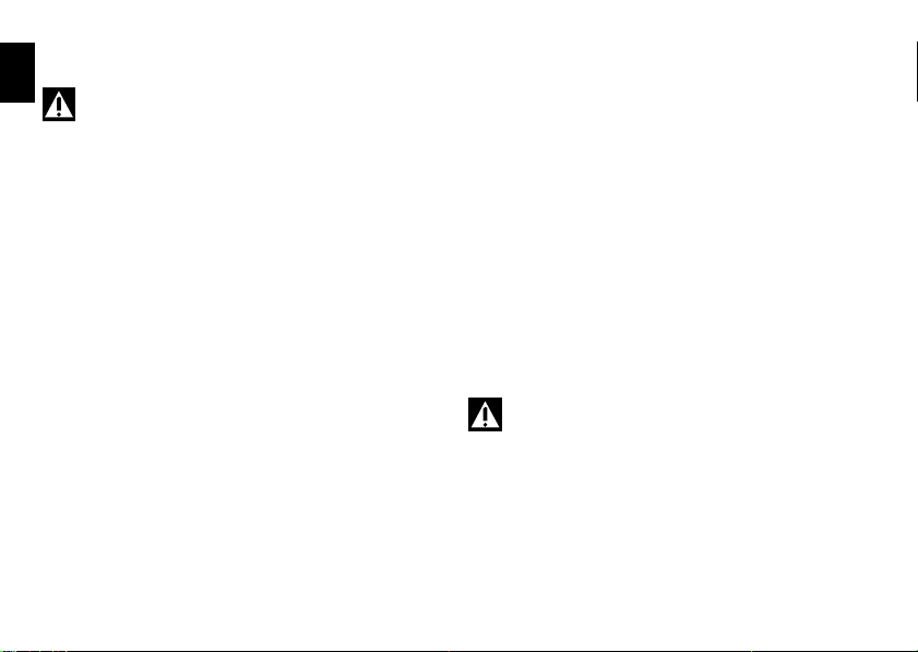
Page 64

Riding the motorcycle
Running-in recommendations
Maximum rpm (fig. 49)
Rpm limits to be observed during the running-in period and in
normal use:
1) up to 1000 km;
2) from 1000 to 2500 km.
Up to 1000 km
During the first 1000 km, keep an eye on the rev counter. It
should never exceed
5,500÷6,000 rpm.
During the first hours of riding, it is advisable to run the
engine at varying load and rpm, though still within
recommended limit.
For this reason, roads with numerous bends and hilly areas
are ideal for running in the engine, brakes and suspension.
For the first 100 km use the brakes gently. Avoid sudden or
prolonged braking. This will allow the friction material on the
brake pads to bed in against the brake discs.
To allow all the mechanical moving parts in the motorcycle to
adapt to one another, and to avoid shortening the life of the
main engine components, it is advisable to avoid sudden
acceleration and running the engine at high rpm for too long,
especially uphill.
It is also advisable to check the drive chain frequently and
ensure that it is lubricated as required.
E
63
Page 65

From 1000 to 2500 km
0 ÷ 1000 Km
1000 ÷ 2500 Km
fig. 49
At this point, you can squeeze some more power out of your
E
engine. However never exceed
7,000 rpm.
Important
Throughout the running-in period, be careful to stick to
the recommended maintenance schedule and periodic
service intervals indicated in the warranty booklet. Failure to
follow these instructions releases Ducati Motor Holding
S.p.A. from any liability whatsoever for any engine damage
or shorter engine life.
Keeping to the running-in recommendations will ensure
longer engine life and reduce the need for overhauls and retuning.
64
Page 66

Pre-ride checks
Warning
Failure to carry out these checks before starting may
result in damage to the motorcycle and injury to rider.
Before starting, check the following points:
FUEL LEVEL IN THE TANK
Check fuel level in the tank. Fill tank if needed (page 70).
ENGINE OIL LEVEL
Check oil level in the sump through the sight
glass. Top up if needed (page 94).
BRAKE AND CLUTCH FLUID
Check fluid level in the relevant reservoirs (page 78).
COOLANT LEVEL
Check coolant level in the expansion reservoir. Top up if
needed (page 77).
TYRE CONDITION
Check tyre pressure and condition (page 92).
CONTROLS
Work the brake, clutch, throttle and gear change controls
(levers, pedals and twistgrips) and check for proper
operation.
LIGHTS AND INDICATORS
Make sure lights, indicators and horn work properly. Replace
any burnt-out bulbs (page 86).
KEY-OPERATED LOCKS
Ensure that fuel filler plug (page 55) and seat (page 56) are
firmly secured.
STAND
Make sure side stand operates smoothly and is in the correct
position (page 57).
Warning
In case of malfunction, do not ride the motorcycle and
contact a Ducati Dealer or authorised Service Centre.
E
65
Page 67

Starting the engine
A
B
C
D
fig. 50
E
Warning
Before starting the engine, become familiar with the
controls you will need to use when riding (see page 10).
Warning
Never start or run the engine indoors. Exhaust gases
are toxic and may lead to loss of consciousness or even
death within a short time.
1) Move the ignition key to ON (fig. 50). Make sure both the
green light N and the red light on the instrument panel
come on.
Important
The oil pressure light should go out a few seconds after
the engine has started (page 11).
Warning
The side stand must be fully up (in a horizontal position)
as its safety sensor prevents engine start when down.
Note
It is possible to start the engine with side stand down
and the gearbox in neutral. When starting the bike with a
gear engaged, pull the clutch lever (in this case the side stand
must be up).
66
Page 68

2) Check that the stop switch (2, fig. 51) is positioned to
2
3
fig. 51
(RUN), then press the starter button (3, fig. 51).
Important
Do not rev the engine when cold. Allow some time for
oil to reach all points that need lubricating.
E
67
Page 69

Moving off
1) Disengage the clutch by squeezing the clutch lever.
E
2) Push down the gear change lever firmly with the tip of
your foot to engage first gear.
3) Raise the engine revs by turning the throttle twistgrip
while gradually releasing the clutch lever. the motorcycle will
start moving off.
4) Release the clutch lever completely and accelerate.
5) To shift up, close the throttle to slow down engine,
disengage the clutch, lift the gear change lever and let go of
clutch lever.
To change down, proceed as follows: release the twistgrip,
pull the clutch control lever, shortly speed up to help gears
synchronise, shift down (engage next lower gear) and
release the clutch.
The controls should be used correctly and timely: when
riding uphill do not hesitate to shift down as soon as the
motorcycle tends to slow down, so you will avoid stressing
the engine and the motorcycle abnormally.
Important
Avoid sudden acceleration, as this may lead to
misfiring and transmission snatching. The clutch lever should
not be pulled longer than necessary after gear is engaged, or
friction parts may overheat and wear out.
68
Braking
Slow down in time, change down to use the engine brake,
then apply both brakes. Pull the clutch lever before stopping
the motorcycle, to avoid sudden engine stop.
Warning
Use both brake lever and pedal for effective braking.
Never use the brake controls harshly or suddenly as you may
lock the wheels and lose control of the motorcycle.
When riding in the rain or on slippery surfaces, braking will
become less effective. Always use the brakes very gently
and carefully when riding under these conditions. Any
sudden manoeuvres may lead to loss of control. When
tackling long, high-gradient downhill road tracts, shift down
gears to use engine braking. Apply one brake at a time and
use brakes sparingly. Keeping the brakes applied
continuously causes the friction material to overheat and
dangerously reduces braking effectiveness. Underinflated or
overinflated tyres reduce braking efficiency, handling
accuracy and stability in a bend.
Page 70

Stopping the motorcycle
Reduce speed, shift down and release the throttle twistgrip.
Change down to engage first gear and then neutral. Apply
the brakes and bring the motorcycle to a complete stop. To
switch the engine off, simply turn the key to OFF (page 46).
Parking
Stop the motorcycle, then put it on the side stand (see page
57).
To prevent theft, turn the handlebar fully left and turn the
ignition key to the LOCK position.
If you park in a garage or other indoor area, make sure that
there is proper ventilation and that the motorcycle is not near
a source of heat.
You may leave the parking lights on by turning the key to
position P.
Important
Do not leave the key turned to P for long periods or the
battery will run down. Never leave the motorcycle
unattended with the ignition key inserted.
Warning
The exhaust system might be hot, even after engine is
switched off; pay particular attention not to touch exhaust
system with any body part and do not park the vehicle next
to inflammable material (wood, leaves etc.).
Warning
Using padlocks or other locks designed to prevent
motorcycle motion, such as brake disc locks, rear sprocket
locks, and so on is dangerous and may impair motorcycle
operation and affect the safety of rider and passenger.
E
69
Page 71

Refuelling (fig. 52)
Max level
fig. 52
Never overfill the tank when refuelling. The fuel level should
E
always be below the rim of the filler recess.
Warning
Use low-lead fuel with a minimum octane rating of 95
(see “Top-ups” table, page 103).
Check that no fuel is trapped in the filler cap recess.
Warning (USA version)
Use low-lead fuel with a minimum octane rating of 90
(RON+MON)/2 (see “Top-ups” table, page 103).
70
Page 72

Tool kit and accessories (fig. 53)
fig. 53
The compartment under the passenger seat holds:
owner's manual;
the tool kit, which includes:
- Box wrench for spark plugs;
- Tommy bar for plug wrench;
- Double-tip screwdriver;
- Allen wrench for fairings.
E
71
Page 73

Main maintenance operations
4
5
1
2
3
fig. 54
E
Removing the fairing
Some parts of the motorcycle fairing have to be removed for
certain maintenance or repair operations.
Warning
If parts that have been removed are not refitted
correctly they may become loose suddenly while riding and
cause you to lose control of your motorcycle.
Important
At reassembly always fit nylon washers when
tightening fastening screws to avoid damage to painted parts
and Plexiglas windscreen of headlight fairing.
Side fairings
To remove the fairings, use the Allen wrench accommodated
under the seat to loosen the following:
the two screws (1) securing the fairing panels to the
brackets;
the six screws (2) securing the fairing panels to the headlight
fairing;
the four screws (3) securing the fairing panels to the frame;
the two screws (4) located under the fairing that join the right
fairing panel to the left fairing panel;
the two screws (5) securing the fairing panels to the oil
cooler;
the two screws (6, fig. 55) securing the front of the fairing to
the headlight fairing.
72
Page 74

Note
6
fig. 55
Be careful of the splashguard, which is released by the
fairing panel fastening.
Note
To refit the left fairing panel, lower the side stand and
pass it through the hole in the panel.
E
73
Page 75

Rear-view mirrors
556
fig. 57
3
1
4
3
2
fig. 56
Unscrew the fastening screws (1) of the rear-view mirror.
E
Release the pins (2) from the retaining clips (3) attached to
the headlight fairing bracket (4). Slip off the rubber covers (5)
and disconnect the turn indicator wiring connectors (6).
Repeat the procedure to remove the other rear-view mirror.
Important
On refitting, apply medium-strength threadlocker to
the threads of the screws (1).
74
Page 76

Kit to widen rear-view mirrors mounting
2
1
fig. 58
3
4
fig. 59
Remove the mirrors as previously explained.
Unscrew the two screws (1) and remove the original spacer
(2).
Fit the supplied spacer (3), start the two long screws (4)
(supplied), then tighten them using a suitable Allen wrench.
Reinstall the rear-view mirrors on the headlight fairing.
E
75
Page 77

Headlight fairing
1
fig. 60
E
Note
To remove the headlight fairing, first remove the rearview mirrors and side fairing panels as described above.
Unscrew the two rear screws (1) securing the headlight
fairing to the headlight support.
Note
After refitting the headlight fairing, refit the side
fairings and the rear-view mirrors.
Changing the air filter
Important
Have air filter serviced at a Ducati Dealer or authorised
Service Centre.
76
Page 78

Checking and topping up coolant level
MAX
MIN
3
2
1
fig. 61
(fig. 61)
Check coolant level in the expansion tank on the right side of
the motorcycle; It should be between the two marks (1) and
(2). Mark (2) indicates MAX level; Mark (1) indicates MIN
level.
Top up if the level is below the MIN mark.
Remove the right-hand side fairing (see page 72).
Unscrew the filler plug (3, fig. 61) and add a mixture
consisting of water and antifreeze SHELL Advance Coolant
or Glycoshell (35÷40% of the volume) up to MAX mark.
Refit the filler plug (3) and reassemble all removed parts.
This type of mixture gives the best operating conditions (the
coolant starts to freeze at -20 °C/-4 °F).
Cooling circuit capacity: 2.3
Warning
Place the motorcycle upright on a flat surface and
make sure the engine is cold before proceeding.
cu. dm (litres).
E
77
Page 79

Checking brake and clutch fluid level
fig. 62
Level should never drop below the MIN marks on the tanks
E
(fig. 62) (shown in the figure are the front and rear brake fluid
reservoirs).
If level drops below the limit, air might get into the circuit and
affect the operation of the system involved.
Fluids must be topped up and changed at the intervals
specified in the scheduled maintenance chart reported in the
Warranty Booklet; please contact a Ducati Dealer or
authorised Service Centre.
Important
It is recommended all brake and clutch lines be
changed every four years.
Brake system
If you find excessive play on brake lever or pedal and brake
pads are still in good condition, contact your Ducati Dealer or
Authorised Service Centre to have the system inspected and
any air drained out of the circuit.
Warning
Brake and clutch fluid can damage paintwork and
plastic parts, so avoid contact. Hydraulic oil is corrosive; it
may cause damage and lead to severe injuries. Never mix
fluids of different qualities.
Check that the seals are in good condition.
78
Page 80

Clutch system
fig. 63
If the control lever has exceeding play and the transmission
snatches or jams as you try to engage a gear, it means that
there might be air in the circuit. Contact your Ducati Dealer
or authorised Service Center to have the system inspected
and air drained out.
Warning
Clutch fluid level will increase as clutch plate friction
material wears down. Do not exceed the specified level (3
mm above the minimum level).
E
79
Page 81

Checking brake pads for wear (fig. 64 and
MIN
fig. 64
MIN
fig. 65
fig. 65)
E
Check brake pads wear through the inspection hole in the
callipers.
Change both pads if friction material thickness of even just
one pad is about 1 mm.
Warning
Friction material wear beyond this limit would lead to
metal support contact with the brake disc thus
compromising braking efficiency, disc integrity and rider
safety.
Important
Have the brake pads replaced at a Ducati Dealer or
authorised Service Centre.
80
Page 82

Lubricating cables and linkages
1
fig. 66
Check the outer sheath of the throttle control cables for
damage at regular intervals. The outer plastic cover should
not be flattened or cracked. Work the controls to make sure
the cables slide smoothly inside the sheaths: if you feel any
friction or catching, have the cable replaced by a Ducati
Dealer or Authorised Service Centre.
To avoid this kind of problem with the throttle cable, unscrew
the two retaining screws (1, fig. 66) to open the case and
then grease cable ends and pulley with SHELL Advance
Grease or Retinax LX2 grease.
Warning
Close the case carefully after threading the cables onto
the pulley.
Refit the cover and tighten the screws (1) to 10 Nm.
To ensure smooth operation of side stand joint, clean off any
dirt and apply SHELL Alvania R3 at all points exposed to
friction.
E
81
Page 83

Adjusting throttle control free play
1,5÷2 mm
1,5÷2 mm
fig. 67
1
2
fig. 68
In all steering positions, the throttle twistgrip must have
E
a freeplay of 1,5÷2,0 mm measured
If necessary, adjust it using the adjusters (1 and 2, fig. 68)
located on the steering tube on the right-hand side of the
vehicle.
Adjuster (1) is for throttle opening, adjuster (2) for closing.
Slip the rubber gaiters off the adjusters and slacken the lock
nuts. Adjust both adjusters proportionally: turn clockwise to
increase free play and counter clockwise to reduce free play.
When finished, tighten the check nuts and refit the rubber
gaiters to the adjusters.
82
Page 84

Charging the battery (fig. 69)
+
3
-
2
1
fig. 69
Before charging the battery, it is best to remove it from the
motorcycle.
Remove the left-hand fairing (page 72), unscrew the screw
(1) and remove the bracket (2). Always disconnect the black
negative terminal (-) first, then the red positive terminal (+).
Warning
Batteries develop explosive gases: keep it away from
heat sources.
Charge the battery in a ventilated room.
Connect the battery charger leads to the battery terminals>
red to the positive terminal (+), black to the negative terminal
(-).
Important
Make sure the charger is off when you connect the
battery to it, or you might get sparks at the battery terminals
that could ignite the gases inside the cells.
Always connect the red positive (+) terminal first.
Reinstall the battery on its mount (3) and secure the bracket
(2) with the screw (1). Apply some grease on the fastening
screws to improve conductive capacity and connect the
terminals.
Warning
Keep the battery out of the reach of children.
Charge the battery at 0.9 A for 5÷10 hours.
E
83
Page 85

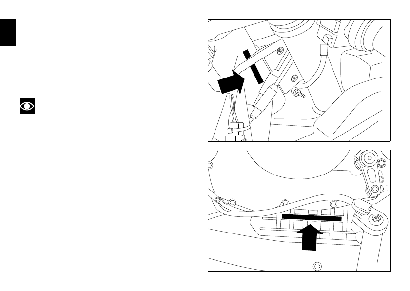
Checking drive chain tension (fig. 70)
.
fig. 70
31 - 33 mm
1
fig. 71
E
Important
Have chain tension adjusted by a Ducati Dealer or
authorised Service Centre.
Motorcycle (on side stand): place ruler at mid-way of chain
lower section, push chain downwards and tension up until
distance between the aluminium section of the swingarm
and chain pin centre is 31 to 33 mm.
Warning
Correct tightening of tensioners check nuts (1) is
critical to rider and passenger safety.
Important
Improper chain tension will lead to early wear of
transmission parts.
84
Page 86

Lubricating the drive chain
The chain fitted on your motorcycle has O-rings to protect its
moving parts from dirt, and to hold the lubricant inside.
The seals might be irreparably damaged if the chain is
cleaned using any solvent other than those specific for O-ring
chains or washed using steam or water cleaners.
After cleaning, blow the chain dry or dry it using absorbent
material and apply SHELL Advance Chain or Advance Teflon
Chain on each link.
Important
Using non-specific lubricants may lead to severe
damage to chain, front and rear sprocket.
E
85
Page 87

Replacing the high and low beam bulbs
1
LO
HI
fig. 72
3
2
A
fig. 73
Before replacing a burnt-out bulb, make sure that the new
E
bulb complies with the voltage and wattage specified in the
“Wiring diagram” paragraph, page 110. Always test the new
bulb before refitting any parts you have removed.
Shown in fig. 72 are the locations of the low beam bulb (LO),
high beam bulb (HI) and parking light bulb (1).
Headlight
To gain access to the left-hand bulb, remove the cover (2) by
pressing the lever (A).
Rotate the locking ring nut (3) of the upper bulb body anticlockwise and extract the burnt-out bulb. Replace with a bulb
of equal rating.
On refitting, rotate the locking ring nut (3) clockwise to
secure the bulb in place.
The right-hand bulb is replaced in the same way.
86
Page 88

Note
To replace the headlight bulbs, there is no need to
disconnect the main wiring harness from the headlight bulb
holder.
Note
Be careful to hold the new bulb at the base only. Never
touch the transparent body with your fingers or it will blacken
resulting in reduced bulb brilliancy.
Refitting
After changing the burnt-out bulb, replace the cover and
close it by pressing it against the lever.
E
87
Page 89

Replacing the parking light bulb
1
fig. 74
To gain access to the parking light bulbs (1), insert your hand
E
into the light support and extract the bulb holders from their
seat; turn the bulb ring nut (1) counter clockwise and extract
the burnt-out bulb.
Replace the burnt-out bulb.
On refitting, turn the bulb (1) clockwise to secure it.
88
Page 90

Rear turn indicators (fig. 75)
4
3
fig. 76
1
2
fig. 75
To change the rear turn indicator bulbs, rotate the indicator
body (1) through one quarter of a turn so that the lens is up
and extract indicator body from the indicator light unit.
The bulb has a bayonet-type end fitting: to remove it, push it
in and turn it counter-clockwise. Push in the new bulb and
turn it clockwise until it clicks into place. Refit the indicator
body (2) to its support and rotate it by a quarter of a turn.
Number plate light (fig. 76)
To access the number plate light bulb, unscrew the screw (3)
securing the cover (4). Remove the bulb and replace it.
E
89
Page 91

Beam setting (fig. 77)
10 m
9
10
x
x
fig. 77
To check the headlight aim, place the motorcycle upright
E
with the tyres inflated to the correct pressure and one person
sitting astride the motorcycle. The motorcycle should be
perfectly vertical, with its longitudinal axis at right angles to a
wall or screen at a distance of 10 metres. then draw a
horizontal line dictated by headlamp centre and a vertical one
in line with the longitudinal axis of motorcycle.
If possible, perform this check in dim light.
Switch on the low beam headlight.
The height of the light spot (measured at the upper limit
between dark and lighted-up area) should not exceed 9/10th
of the height from ground of headlamp centre.
Note
This is the procedure specified by Italian regulations for
checking the maximum height of the light beam.
Owners in other countries should adapt this procedure to the
regulations in force in the country where the motorcycle is
used.
90
Page 92

The side position of the left beam can be corrected using the
1
2
fig. 78Afig. 79
screw (1, fig. 78) on the rear side of the headlamp. Turn the
screw clockwise to move the beam to the right, counter
clockwise to move it to the left.
The height of the left beam can be corrected using the screw
(2, fig. 78) on the rear side of the headlamp. Turn the screw
clockwise to lower the beam, anticlockwise to raise it.
Repeat the above procedure to adjust the right-hand
headlamp.
Warning
The headlight might fog up if the vehicle is used under
the rain or after washing.
Switch headlight on for a short time to dry up any
condensate.
Rear-view mirror adjustment (fig. 79)
The rear-view mirror can be adjusted manually by pressing on
point (A).
E
91
Page 93

Tubeless tyres
Front tyre pressure:
E
2.1 bar - 2.3 Kg/sq. cm
Rear tyre pressure:
2.2 bar - 2.4 Kg/sq. cm
As tyre pressure is affected by temperature and altitude
variations, check and adjust them whenever you are riding in
areas where there are large variations in temperature or
altitude.
Important
Check and adjust the pressures with the tyres cold.
To avoid front wheel rim distortion, when riding on bumpy
roads, increase tyre pressure by 0.2 - 0.3 bar.
92
Tyre repair or change (Tubeless tyres)
With minor punctures, tubeless tyres take a long time to
deflate, as they tend to hold the air inside. If you find low
pressure on one tyre, check the tyre for punctures.
Warning
Punctured tyres must be replaced.
Replace with tyres of the original brand and type.
Be sure to tighten the valve dust caps securely to prevent
leaks while riding. Never fit tyres with inner tubes, as these
can cause the tyre to burst suddenly, with possibly serious
consequences for the rider and passenger.
After replacing a tyre, the wheel must be balanced.
Important
Do not remove or alter the position of the wheel
balancing weights.
Note
Have the tyres replaced at a Ducati Dealer or
authorised Service Centre. Correct removal and installation
of the wheels is essential.
Page 94

Minimum tread depth
S
fig. 80
Measure tread depth (S, fig. 80) at the point where tread is
most worn down.
It should not be less than 2 mm, and in any case not less than
the legal limit.
Important
Visually inspect the tyres at regular intervals for cracks
and cuts, especially on the side walls, and bulges or large
stains that indicate internal damage. Replace them if badly
damaged.
Remove any stones or other foreign bodies stuck in the
tread.
E
93
Page 95

Checking engine oil level (fig. 81)
21
fig. 81
–10
Unigrade
Multigrade
0 10 20 30 40 C
40
20W–40 20W–50
15W–40 15W–50
10W–40
10W–30
10W
20W
20
30
Engine oil level can be checked through the
E
sight glass (1) provided on the clutch cover. When checking
oil level, the motorcycle should be perfectly upright and the
engine cold. Oil level should be between the marks on the
sight glass. If level is low, top up with SHELL Advance 4T
Ultra engine oil. Remove the filler plug (2) and top up to
correct level. Replace the filler cap.
Important
Engine oil and oil filters must be changed by a Ducati
Dealer or authorised Service Center at the intervals specified
in the scheduled maintenance chart reported in the Warranty
Card.
Oil viscosity
SAE 15W-50
The other viscosity degrees indicated in the table can be
used if the local average temperature is within the limits
specified for that oil viscosity.
94
Page 96

Cleaning and replacing the spark plugs
1
0,8 ÷ 0,1 mm
fig. 82
(fig. 82)
Spark plugs are an important part of the engine and should
be checked at regular intervals.
This operation provides an indication of engine condition.
Have the spark plugs inspected or replaced at a Ducati Dealer
or Authorised Service Centre. Firstly, they will check the
colour of the ceramic insulator of the central electrode: an
even brown colour is a sign that the engine is in good running
order.
Note
Inspect the centre electrode for wear and check spark
plug gap, which should be:
0.8-0.1 mm.
Important
A gap outside the specified limits will adversely affect
engine performance and may lead to difficult starting or
erratic idling.
E
95
Page 97

General cleaning
To preserve the original shine on metal surfaces and
E
paintwork, wash and clean your motorcycle at regular
intervals depending on the type of use and according to the
particular road conditions. Use specific products, where
possible biodegradable. Avoid aggressive detergents or
solvents.
Only use water and neutral soap to clean the Plexiglas and
the seat.
Clean the aluminium components regularly and by hand. Use
specific detergents for aluminium that do NOT contain
abrasive substances or caustic soda.
Note
Do not use abrasive or steel wool sponges, use only a
soft cloth.
The warranty does not apply to motorcycles where there is
evidence of poor maintenance.
Important
Do not wash your motorcycle right after use. When the
motorcycle is still hot, water drops will evaporate faster and
spot hot surfaces. Never clean the motorcycle using hot or
high-pressure water jets. Cleaning the motorcycle with a
high pressure water jet may lead to seizure or serious faults
in the front fork, wheel hub assembly, electric system,
headlight (fogging), front fork seals, air inlets or exhaust
silencers, with consequent loss of safety.
96
Clean off stubborn dirt or exceeding grease from engine
parts using a degreasing agent. Be sure to avoid contact with
drive parts (chain, sprockets, etc.) Rinse with warm water
and dry all surfaces with chamois leather.
Warning
There may be loss of braking efficiency immediately
after washing the motorcycle. Never grease or lubricate the
brake discs. Loss of braking and further accidents may occur.
Clean the discs with an oil-free solvent.
Warning
The headlight might fog up due to washing, rain or
moisture.
Switch headlight on for a short time to dry up any
condensate.
Page 98

Storing the motorcycle
If the motorcycle is to be left unused for a long period, it is
advisable to carry out the following operations first:
clean the motorcycle;
empty the fuel tank;
pour a few drops of engine oil into the cylinders through the
spark plug bores, then turn the engine over by hand a few
times to form a protective film of oil on the inner walls of the
cylinder;
place the motorcycle on the service stand;
disconnect and remove the battery.
Battery should be checked and charged (or replaced, as
required) whenever the motorcycle has been left unridden
for over a month.
Protect the motorcycle with a specific motorcycle cover that
will not damage the paintwork or retain moisture.
This type of motorcycle cover is available from Ducati
Performance.
Important notes
The legislation in some countries (France, Germany, Great
Britain, Switzerland, etc.) sets certain noise and pollution
standards.
Periodically carry out the required checks and replace parts
as necessary, using Ducati original spare parts, in compliance
with the regulations in the country concerned.
E
97
Page 99

Maintenance
E
Programmed maintenance plan: operations to be carried out by the dealer
List of operations and type of intervention
[set mileage (km/mi) or time interval *]
Change the engine oil
Change the engine oil filter
Clean the engine oil pick-up filter
Check engine oil pressure
Check/adjust the valve clearances (1)
Check the tension of the timing belts (1)
Replace the timing belts
Replace the spark plugs
Check and clean air filter (1)
98
Km. x1000 1 12 24 36 48 60
mi. x1000 0.6 7.5 15 22.5 30 37.5
Months 6 12 24 36 48 60
Page 100

List of operations and type of intervention
[set mileage (km/mi) or time interval *]
Change the air filter
Check throttle body synchronisation and idling (1)
Check the brake and clutch fluid levels
Change the clutch and brake fluid
Check and adjust the brake and clutch control cables
Check/lubricate the throttle/choke cables
Check tyre pressure and wear
Check the brake pads. Replace if necessary
Check the steering head bearings
Check the drive chain tension, alignment and lubrication
Check the clutch disc pack. Change, if necessary (1)
Check the coolant level
Change the coolant
Check electric fan operation and cooling circuit sealing
Check the rear wheel cush drive
Check the wheel hub bearings
Check the indicators and lighting
Check tightness of nuts and screw securing the engine to the frame
Check the sidestand
Km. x1000 1 12 24 36 48 60
mi. x1000 0.6 7.5 15 22.5 30 37.5
Months 6 12 24 36 48 60
E
99
 Loading...