

US/CANADA
1

Introduction
We'd like to welcome you among Ducati enthusiasts
and congratulate you on your excellent choice of
motorcycle. We imagine you'll be riding your Ducati
motorcycle for long trips as well as short daily
excursions. Ducati Motor Holding S.p.A. wishes you
smooth and enjoyable riding.
Your motorcycle is the result of constant research
and development by Ducati Motor Holding S.p.A., so
it's important that the standard of quality is upheld
through careful observance of the scheduled
maintenance chart and the use of original spare parts.
In the Owner's Manual you'll find instructions for
performing small maintenance procedures.
The most important servicing and maintenance
procedures are contained in the Service Manual
available at Authorized Service Centers of Ducati
Motor Holding S.p.A..
2
In your own interest and safety, and in order to
guarantee product reliability, we strongly
recommend that you go to an Authorized Dealer or
Service Center for any servicing included on the
scheduled maintenance chart (see p. 258)
Our highly skilled staff has access to the special tools
and equipment needed to perform any servicing
procedure with expertise. They use only Ducati
original spare parts as the best guarantee for full
interchangeability, smooth running and long life.
All Ducati motorcycles come with a Warranty
Booklet.
The Warranty does not extend to motorcycles used
in competitions or competitive trials.
Any tampering or even partial modification of the
components will result in automatic invalidation of
Warranty rights.
Incorrect or insufficient servicing procedures, use of
non-original spare parts or parts not explicitly
approved by Ducati may lead to the invalidation of the
Warranty, besides potential damage and reduced
performance.

Table of contents
Introduction 2
Safety guidelines 7
Warning symbols used in the manual 7
Permitted use 8
Rider's obligation 8
Reporting safety defects 10
Rider education 11
Clothing 11
“Best Practices” for safety 12
Refueling 14
Carrying the maximum load allowed 15
Dangerous products - warnings 16
Vehicle ID number 18
Engine ID number 19
Plate positioning 20
Noise and exhaust emission control system
information
California emission control warranty statement
Your warranty rights and obligations
26
27
Manufacturer’s warranty coverage 27
Owner's warranty responsibilities: 27
California evaporation emission system 28
Ducati limited warranty on emission
control system
28
Instrument Panel (Dashboard) 31
Acronyms and abbreviations used in the Manual 34
Technological Dictionary 34
Function pushbuttons 38
How to set/display parameters 39
Main functions 46
Riding Mode 53
DTC 57
EBC 63
DQS 67
Menu 1 functions 71
Menu 1 functions: Odometer (TOT) 72
Menu 1 functions: Trip 1 (TRIP 1) 74
Menu 1 functions: Trip 2 (TRIP 2) 76
Menu 1 functions: Partial fuel reserve counter
(TRIP FUEL)
Menu 1 functions: LAP time 80
MENU 2 functions 83
MENU 2 functions: Coolant temperature 84
MENU 2 functions: Instantaneous fuel
consumption
78
86
3

MENU 2 functions: Average fuel consumption
87
MENU 2 functions: Average speed 88
MENU 2 functions: Trip time 89
MENU 2 functions: External air temperature 90
Auxiliary functions 91
CLOCK 93
Service warning (SERVICE) 94
OIL SERVICE zero indication 94
OIL SERVICE or DESMO SERVICE indication 96
Warnings/Alarms (Warning) 97
Error indication 101
Displayed error description 102
Side stand status display 106
Setting MENU 107
Customizing Riding Modes 110
Customizing Riding Modes: ABS setting 114
Customizing Riding Modes: Electronic suspension
setting
117
Customizing Riding Modes: Display setting 122
Customizing Riding Modes: DQS enable/disable 124
Customizing Riding Modes: DTC level setting 126
Customizing Riding Modes: Engine setting 128
Customizing Riding Modes: EBC level setting 132
Customizing Riding Modes: Restore
default settings
134
Engine rpm digital indication (RPM) 135
Battery voltage 136
DDA 138
Pin Code 142
4
Changing the PIN CODE 145
Clock setup 149
Setting the date 152
Setting the display background 155
LAP 157
Setting the unit of measurement 163
Other functions 170
Display background color 177
Light control 178
The Immobilizer system 181
Keys 181
Operation 181
Duplicate keys 182
Vehicle release through PIN CODE 182
Controls 185
Position of motorcycle controls 185
Key-operated ignition switch and steering lock 186
LH switch 187
Clutch lever 188
RH switch 189
Throttle twistgrip 190
Front brake lever 190
Rear brake pedal 191
Gear change pedal 191
Adjusting the position of the gearchange and rear
brake pedals
192

Main components and devices 194
Position on the vehicle 194
Tank filler plug 195
Seat lock 196
Side stand 197
Steering damper 198
Adjusting the front fork 199
Adjusting the rear shock absorber 200
Changing the motorcycle track alignment 201
Riding the motorcycle 202
Break-in recommendations 202
Pre-ride checks 204
Starting the engine 206
Moving off 208
Braking 209
Stopping the motorcycle 212
Parking 212
Refueling 213
Tool kit and accessories 214
Main maintenance operations 215
Removing the fairing 215
Side fairings 215
Change the air filter 216
Checking and topping up coolant level 217
Checking brake and clutch fluid level 219
Checking brake pads for wear 221
Charging the battery 222
Charging and maintenance of the battery during
winter storage
Checking drive chain tension 227
Chain lubrication 228
Replacing the high and low beam bulbs 229
Rear turn indicators 230
Beam setting 231
Rearview mirror adjustment 233
Tubeless tires 234
Checking engine oil level 236
Cleaning and replacing the spark plugs 237
Cleaning the motorcycle 238
Storing the motorcycle 239
Important notes 239
225
Scheduled maintenance chart 240
Scheduled maintenance chart: operations to be
performed by the Dealer
Scheduled maintenance chart: operations to be
performed by the customer
240
244
Technical data 245
Overall dimensions 245
Weights 245
Engine 247
5

Timing system
Performance data 248
Spark plugs 248
Fuel system 248
Brakes 249
Transmission 250
Frame 251
Wheels 251
Tires 251
Suspensions 251
Exhaust system 252
Available colors 252
Electrical system 252
247
Routine maintenance record 258
6
Safety guidelines
Your safety and that of others are very important.
Ducati Motor Holding S.p.A. urges you to ride your
motorcycle responsibly.
Before using your motorcycle for the first time,
please read this manual carefully from start to finish
and closely follow the guidelines. This will allow you
to obtain all information regarding a correct use and
maintenance.
If you have any doubts or questions, consult a Dealer
or Authorized Service Center.
Warning symbols used in the manual
Different forms of information regarding potential
hazards that may affect you or others have been
used. These include:
- Safety stickers on the motorcycle;
- Safety warnings preceded by a warning symbol
and by one or the two words Caution or
Important.
Warning
Failure to observe these instructions may lead
to a hazardous situation and cause severe injury to
the rider or others, or even death.
Important
Possibility of damaging the motorcycle and/or
its components.
Note
Additional information regarding the job being
performed.
The terms RIGHT and LEFT are referred to the
motorcycle viewed from the riding position.
7
Permitted use
This motorcycle must be used only on road surfaces
with asphalt or flat and even pavement.
This motorcycle may not be used on dirt roads or for
off-road riding.
Warning
Using the bike off-road may cause the rider to
lose control, which in turn may lead to vehicle
damage, injury or death.
Warning
This motorcycle must not be used for towing or
for the addition of a sidecar, since this may cause a
loss or control and consequent accident.
This motorcycle carries the rider and may carry one
passenger upon installation of a dedicated kit
performed exclusively at a Ducati Dealer or
Authorized Service Center.
Rider's obligation
All riders must hold a driver's license.
Warning
Riding without a license is illegal and punishable
by law. Make sure you always have your license on
you when setting out on the motorcycle. Do not
allow inexpert riders or those not in possession of an
authorized driver's license to ride the motorcycle.
Do not ride the motorcycle when under the influence
of alcohol or drugs.
Warning
Riding under the influence of alcohol or drugs is
illegal and punishable by law.
Avoid taking medication before riding the motorcycle
if you have not consulted your doctor about potential
side effects.
Warning
The total weight of the motorcycle in running
order with rider, passenger, baggage and additional
accessories must not exceed 816 lb/ 370 kg.
8
Warning
Some medications may induce sleepiness or
other effects that impair reflexes and the ability of the
rider to control the motorcycle, which may lead to
accident.
Some countries require mandatory insurance
coverage.
Warning
Check the laws applicable to your country. Take
out an insurance policy and keep the policy in a safe
place along with the other motorcycle documents.
To protect the safety of the rider and/or passenger,
some countries have made it a law to wear a
homologated helmet.
Warning
Check the laws applicable to your country.
Riding without a helmet may be punishable by a fine.
Warning
Failure to be wearing a helmet in case of
accident increases the chance of serious injury and
even death.
Warning
Make sure that the helmet is in compliance with
safety specifications, provides excellent visibility, is
the correct size for the head, and has the DOT
(Department of Transportation) label affixed to the
helmet surface.
Laws regulating traffic vary from country to country.
Check the laws in force in your country before riding
the motorcycle and pay strict adherence to them .
Warning
Tampering with Noise Control System
Prohibited. Federal Law prohibits the following acts
or causing thereof:
1) the removal or rendering inoperative by any
person, other than for purposes of maintenance,
repair, or replacement, of any device or element
of design incorporated into any new vehicle for
the purpose of noise control prior to its sale or
delivery to the ultimate purchaser or while it is in
use; or
2) the use of the vehicle after such device or
element of design has been removed or
rendered inoperative by any person.
Among the acts presumed to constitute tampering
are those listed below:
1) Removal of, or puncturing the muffler, baffles,
header pipes or any other component that
conducts exhaust gases.
2) Removal or puncturing of any part of the intake
system.
3) Lack of proper maintenance.
9

4) Replacing any moving part of the vehicle, or parts
of the exhaust or intake system, with parts other
than those specified by the manufacturer.
This product should be checked for repair or
replacement if the motorcycle noise has increased
significantly through use. Otherwise, the owner may
become subject to penalties under state and local
ordinances.
10
Reporting safety defects
If you believe your vehicle has a defect that could
cause a crash or cause injury or death, you should
immediately inform the National Highway Traffic
Safety Administration (NHTSA), in addition to
notifying Ducati North America, 10443 Bandley Drive
Cupertino, California, 95014, Tel: 001.408.253.0499,
Fax: 001.408.253.4099. If NHTSA receives similar
complaints, it may open an investigation, and if it
finds that a safety defect exists in a group of vehicles,
it may order a recall and remedy campaign. However,
NHTSA cannot become involved in individual
problems between you, your dealer, or Ducati North
America. To contact NHTSA, you may either call the
Auto Safety Hotline toll-free at 1-800-424-9393 (or
366-0123 in Washington, D.C. area) or write to:
NHTSA, 1200 New Jersey Avenue SE W43-488,
Washington, D.C. 20590. You can also obtain other
information about motor vehicle safety from the
Hotline.
Rider education
Accidents are frequently due to inexperience. Riding,
maneuvering and or braking are carried out differently
from other vehicles.
Warning
A rider's lack of preparation or an inappropriate
use of the vehicle may result in a loss of control,
death or serious damage.
Check your knowledge of current “TRAFFIC LAWS“;
read carefully and familiarize yourself with the
contents of the M.O.M (Motorcycle Operator
Manual) pertinent to your state available at the M.S.F.
website (Motorcycle Safety Foundation) (www.msfusa.org).
You are strongly recommended to take a riding
course approved by the M.S.F. (Motorcycle Safety
Foundation).
Clothing
Clothing in the use of the motorcycle plays an
important role in safety, as the motorcycle provides a
person no protection from impact in the same way as
an automobile.
Suitable clothing includes: helmet, eye protection,
gloves, boots, long-sleeved jacket and long pants.
- The helmet must have the requisites as listed on
p. 9, if the helmet model has no visor, use suitable
goggles;
- Gloves must have five fingers and be made of
leather or other abrasion-resistant material;
- Boots or shoes used for riding must have non-slip
soles and ankle protection;
- Jacket and pants, or even riding suits, must be
made of leather or abrasion-resistant material and
in a color with inserts that are very visible.
Important
In any case, avoid wearing loose or floppy
clothing that can become stuck in the motorcycle
parts.
11
Important
For your safety this type of clothing must be
used in both summer and winter.
Important
For the safety of the passenger, make sure that
he or she also wears appropriate clothing.
12
“Best Practices” for safety
Before, during and after use, remember to follow
some simple rules that are extremely important for
safety and for maintaining the motorcycle at top
efficiency.
Important
During the break-in period, carefully observe the
instructions contained on page 202. Failure to follow
these instructions releases Ducati Motor Holding
S.p.A. from any liability whatsoever for any engine
damage or shorter engine life.
Warning
Do not ride the motorcycle unless you are well
familiarized with the controls to be used during the
ride.
Before starting the motorcycle, always performs the
checks detailed in this manual (see page 204).
Warning
Failure to perform checks may cause damage to
the vehicle and serious injury to the rider and/or
passenger.
Warning
Start the engine when outdoors or in a well
ventilated place. Never start the engine in a closed
environment.
Exhaust gases are poisonous and may lead to loss of
consciousness or even death within a short time.
During the ride, assume a correct body position and
make sure the passenger does the same.
Important
The rider should ALWAYS keep both hands on
the handlebar.
Important
Both rider and passenger should keep their feet
on the footpegs when the motorcycle is in motion.
Important
The passenger should always hold on to the
strap on passenger seat with both hands.
Important
Be very careful when maneuvering
intersections or when riding in areas near exits from
private grounds, parking lots or access roads to
highways.
Important
Be sure you are clearly visible and do not ride in
the blind spot of the vehicles ahead.
Important
ALWAYS signal your intention to turn or pull
over to the next lane with due warning using the turn
indicators.
Important
Park your motorcycle where no one is likely to
hit it, and use the side stand.
Never park on uneven or soft ground or your
motorcycle may fall over.
Important
Visually inspect the tires at regular intervals for
cracks and cuts, especially on sidewalls, bulges or
large spots which are indicative of internal damage.
Replace them if badly damaged.
Remove any stones or other foreign bodies caught in
the tread.
13
Warning
The engine, exhaust pipes and mufflers stay hot
for a long time after the engine has been turned off.
Be especially careful not to touch the exhaust system
with any part of the body and never park the
motorcycle near flammable materials (wood, leaves,
etc.).
Warning
When you leave the motorcycle unattended,
always remove the ignition key and make sure it is
inaccessible to anyone unsuitable to ride the
motorcycle.
14
Refueling
Refuel the motorcycle in an open area and with the
engine switched off.
Do not smoke or ever use flames during refueling.
Be careful never to drop fuel on the engine or
exhaust pipe.
When refueling, do not fill the tank completely: fuel
should never be touching the rim of filler recess.
When refueling, avoid inhaling fuel vapors and take
care that they do not come in contact with eyes, skin
or clothing.
Warning
The vehicle is compatible only with fuel having
a maximum ethanol content of 10% (E10). Using
fuels with ethanol content over 10% is prohibited.
Using them could result in severe damage of the
engine and motorcycle components. Using fuel with
ethanol content over 10% will render the Warranty
null and void.
Warning
In case of malaise caused by prolonged
inhalation of fuel vapors, stay outdoors and consult a
physician. In case of contact with eyes, rinse eyes
thoroughly with water. In case of contact with skin,
wash the area immediately with soap and water.
Warning
Fuel is highly flammable. If it accidentally spills
onto clothes, change them.
Carrying the maximum load allowed
Your motorcycle is designed for long-distance riding
with the maximum load allowed carried in full safety.
Even weight distribution is critical to preserving these
safety features and avoiding difficulties when
performing sudden maneuvers or riding on bumpy
roads.
Warning
Do not exceed the total permitted weight for
the motorcycle and pay attention to the information
below regarding load capacity.
Information about carrying capacity
Important
Arrange your luggage or heavy accessories in
the lowest possible position and close to motorcycle
center.
Important
Never fix bulky or heavy objects to the steering
head or front mudguard, as this would affect stability
and be dangerous.
15
Important
Be sure to secure the luggage to the supports
provided on the motorcycle as firmly as possible.
Improperly secured luggage may affect stability.
Important
Do not insert any objects you may need to carry
into the gaps of the frame, as these may interfere
with moving parts.
Warning
Make sure tires are inflated to the correct
pressure indicated at page 234 and that they are in
good condition.
16
Dangerous products - warnings
Used engine oil
Warning
Prolonged or repeated contact with used engine
oil may cause skin cancer. If exposed to used engine
oil on a daily basis, make it a rule to wash your hands
thoroughly with soap immediately after use. Keep
away from children.
Brake lining debris
Never attempt to clean the brake assembly using
compressed air or a dry brush.
Brake fluid
Warning
Avoid spilling brake fluid onto plastic, rubber or
painted parts of the motorcycle to avoid the risk of
damage. Protect these parts with a clean shop rag
before servicing the motorcycle. Keep away from
children.
Warning
The brake fluid used in the brake system is
corrosive. In the event of accidental contact with
eyes or skin, wash the affected area with generous
quantities of running water.
Coolant
Engine coolant contains ethylene glycol, which may
ignite under particular conditions, producing invisible
flames. Although the flames from burning ethylene
glycol are not visible, they are still capable of causing
severe burns.
Warning
Take care not to spill engine coolant on the
exhaust system or engine parts. These parts may be
hot and ignite the coolant, which will subsequently
burn with invisible flames.
Coolant (ethylene glycol) is an irritant and is
poisonous when ingested. Keep away from children.
Never remove the radiator cap when the engine is
hot. The coolant will be scalding hot and is under high
pressure.
The cooling fan operates automatically: keep hands
well clear and make sure your clothing does not get
caught in the fan.
Battery
Warning
The battery gives off explosive gases; keep it
away from any source of ignition such as sparks,
flames and cigarettes. Charge the battery in a wellventilated area.
17
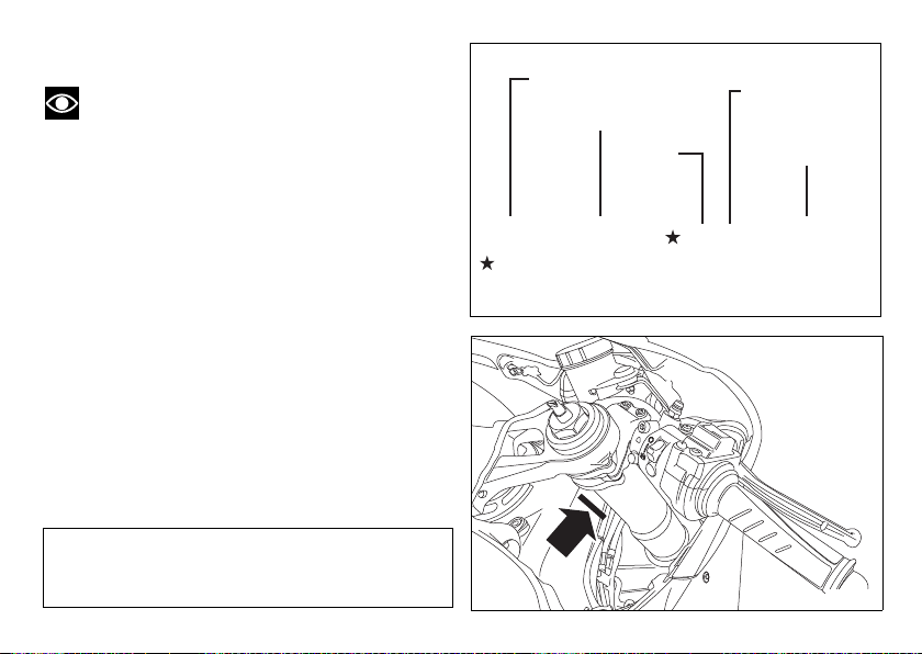
Vehicle ID number
fig. 2
ZDM 1 4 B P W C B 0 0 0 0 0 0
DUCATI
TYPE OF
MOTORCYCLE
MODEL
YEAR
PLANT OF
MANU FACTURE
SEQUENTIAL
NUMBER
{
{
{
Varies-can be Ø thru 9 or X (Check digit)
fig. 1
Note
These numbers identify the motorcycle model
and should always be indicated when ordering spare
parts.
We recommend that you note the frame number of
your motorcycle in the space below.
Frame number
18
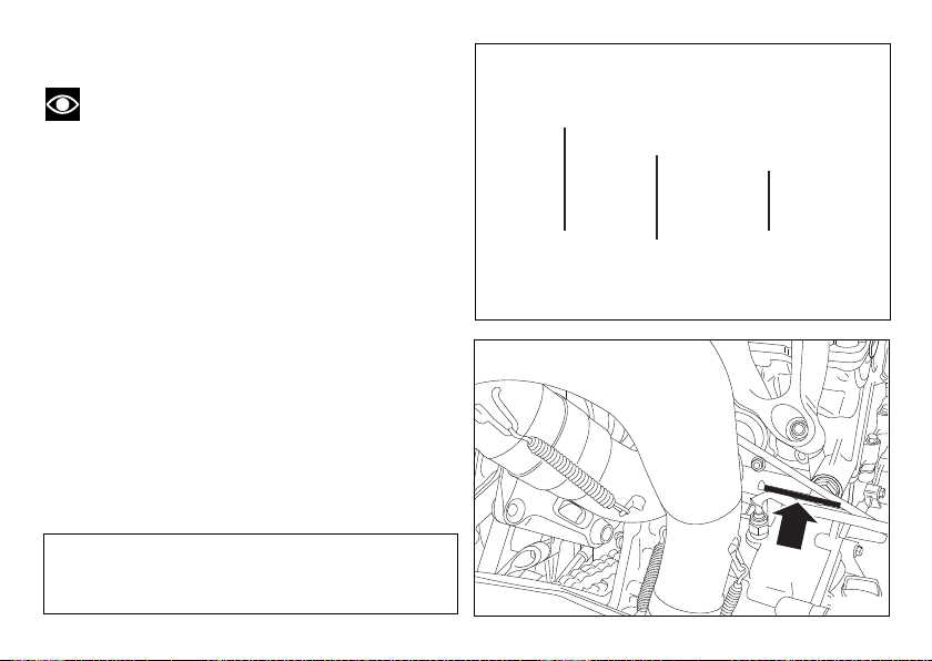
Engine ID number
fig. 4
4 B P
C 0 0 0 0 0 0
ENGINE
TYPE
MODEL
YEAR
SEQUENTIAL
NUMBER
{
{
fig. 3
Note
These numbers identify the motorcycle model
and should always be indicated when ordering spare
parts.
We recommend that you note the engine number of
your motorcycle in the space below.
Engine number
19
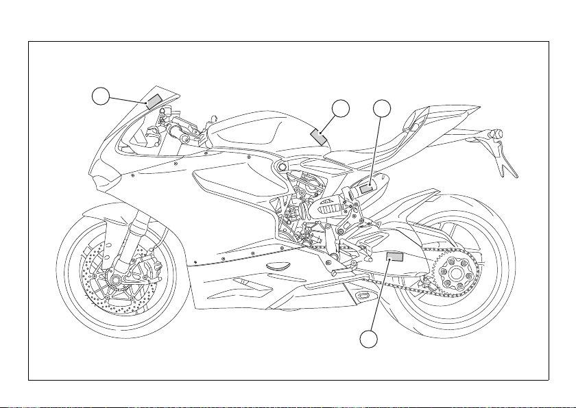
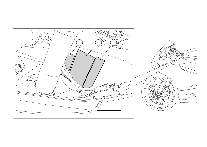
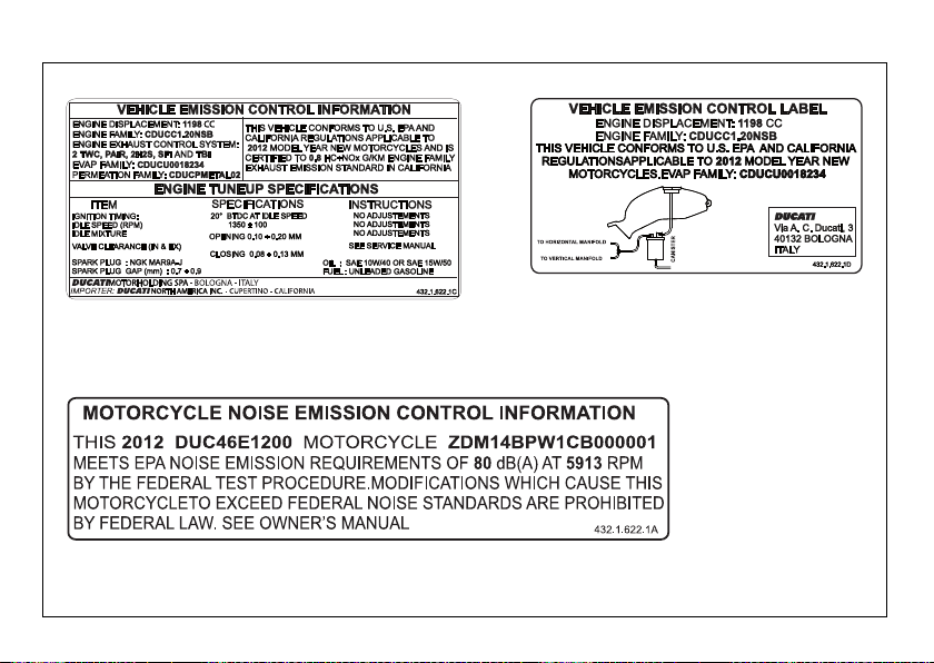
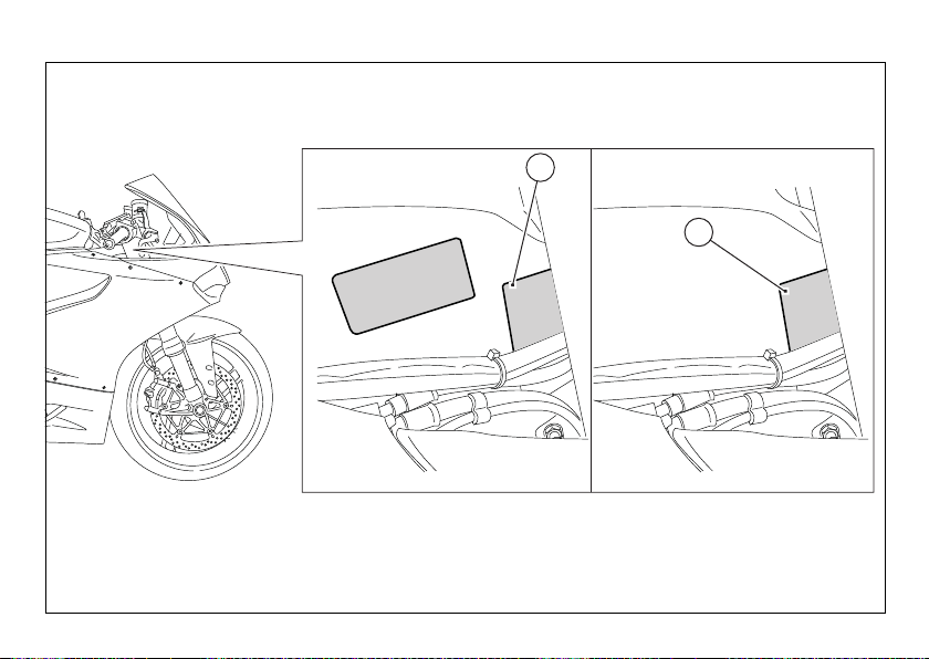
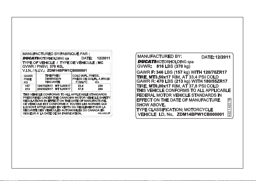
Plate positioning
1
2 3
4
fig. 5
20
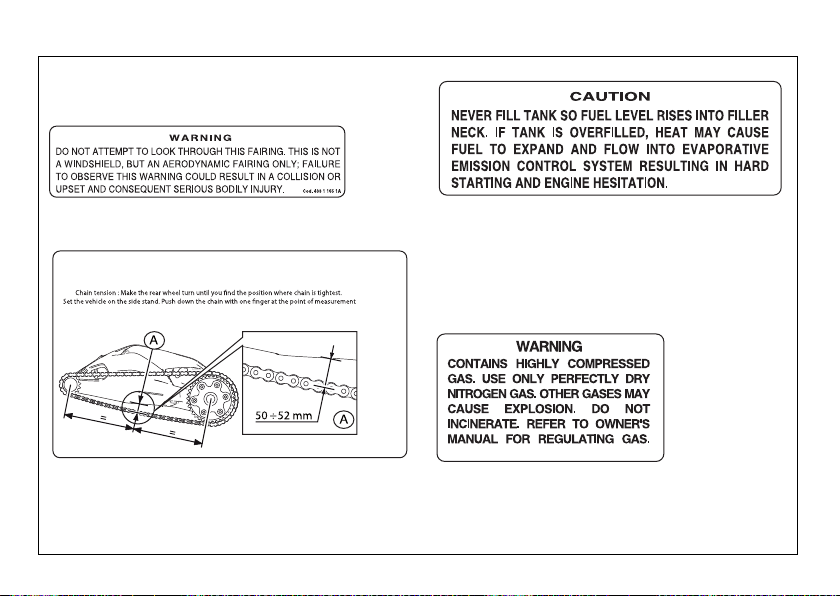
1
4
5
6
Appoggiare il veicolo sulla stampella laterale. Con la sola pressione del dito, spingere la catena verso
il basso nel punto di misura e poi rilasciarla. Misurare la distanza (A) tra il centro dei perni della catena
e l’alluminio del forcellone, che deve risultare : A = 50
÷
52 mm
and realese. Measure the distance (A) between the chain pins centre and swingarm aluminium edge.
Reading must be: A = 50
÷ 52 mm
fig. 6
21
5 6
7
fig. 7
22
6
5
7
fig. 8
23
8(Only Canada)
9
fig. 9
24
9
8
(Only Canada)
fig. 10
25

Noise and exhaust emission control
system information
combustion chamber through the air cleaner and the
throttle body.
Source of Emissions
The combustion process produces carbon monoxide
and hydrocarbons. Control of hydrocarbons is very
important because under certain conditions, they
react to form photochemical smog when subjected
to sunlight.
Carbon monoxide does not react in the same way,
but is toxic. Ducati utilizes lean carburetor settings
and other systems to reduce carbon monoxide and
hydrocarbons.
Exhaust Emission Control System
Exhaust Emission Control System is controlled by an
Electronic Control Unit (ECU), and no adjustments
should be made except idle speed adjustments with
the throttle stop screw. The Exhaust Emission
Control System is separate from the crankcase
emission control system.
Crankcase Emission Control System
The engine is equipped with a closed crankcase
system to prevent discharging crankcase emissions
into the atmosphere. Blow-by gas is returned to the
26
Evaporative Emission Control System
The motorcycles are equipped with an evaporative
emission control system which consists of a charcoal
canister and associated piping. This system prevents
the escape of fuel vapors from the engine and fuel
tank.
Problems that may affect motorcycle
emissions
If you are aware of any of the following symptoms,
have the vehicle inspected and repaired by your local
Ducati dealer.
Symptoms:
Hard starting or stalling after starting.
Rough idle.
Misfiring or backfiring during acceleration.
After-burning (backfiring).
Poor performance (drivability) and poor economy.

California emission control warranty
statement
Your warranty rights and obligations
The California Air Resources Board is pleased to
explain the emission control system warranty on your
MY 2012 motorcycle. In California, new motor
vehicles must be designated, built and equipped to
meet the State's stringent anti-smog standards.
Ducati North America, Inc. must warrant the
emission control system on your motorcycle for the
periods of time listed below provided there has been
no abuse, neglect or improper maintenance of your
motorcycle.
Your emission control system may include parts such
as fuel-injection system, the ignition system, catalytic
converter, and engine computer. Also included may
be hoses, belts, connectors and other emissionrelated assemblies. Where a warrantable condition
exists, Ducati North America, Inc. will repair your
motorcycle at no cost to you including diagnosis,
parts and labor.
Manufacturer’s warranty coverage
- 5 years or 30,000 kilometers (18641 miles),
whichever first occurs.
Owner's warranty responsibilities:
- As the motorcycle owner, you are responsible for
the performance of the required maintenance
listed in your owner's manual. Ducati North
America, Inc. recommends that you retain all
receipts covering maintenance on your
motorcycle, but Ducati North America, Inc. cannot
deny warranty solely for the lack of receipts or for
your failure to ensure the performance of all
scheduled maintenance.
- You are responsible for presenting your
motorcycle to a Ducati dealer as soon as a
problem exists. The warranty repairs should be
completed in a reasonable amount of time, not to
exceed 30 days.
- As the motorcycle owner, you should also be
aware that Ducati North America, Inc. may deny
you warranty coverage if your motorcycle or a part
has failed due to abuse, neglect, improper
maintenance or unapproved modifications.
If you have any questions regarding your warranty
rights and responsibilities, you should contact Ducati
North America, Inc. at 001.408.253.0499 or the
California Air Resource Board at 9528 Telstar
Avenue, El Monte, CA 91731.
27
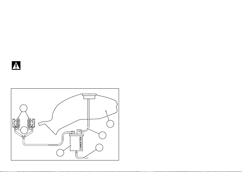
California evaporation emission system
1
5
3
6
2
4
fig. 11
This system consists of (fig. C):
1) Warn air inlet;
2) Canister;
3) Dell’Orto jet;
4) Fuel tank;
5) Breather pipe;
6) Intake manifolds.
Important
In the event of a fuel system malfunction,
contact a Ducati Authorized Service Center.
Ducati limited warranty on emission
control system
Ducati North America, Inc., 10443 Bandley Drive
Cupertino, California, 95014 warrants that each new
1998 and later Ducati motorcycle, that includes as
standard equipment a headlight, tail-light and
stoplight, and is street legal:
A) is designed, built and equipped so as to conform
at the time of initial retail purchase with all applicable
regulations of the United States Environmental
Protection Agency, and the California Air Resources
Board; and
B) is free from defects in material and workmanship
which cause such motorcycle to fail to conform with
applicable regulations of the United States
Environmental Protection Agency or the California Air
Resources Board for a period of use of 30,000
kilometers (18,641 miles) or 5 (five) years from the
date of initial retail delivery, whichever first occurs.
28
I. Coverage
Warranty defects shall be remedied during
customary business hours at any authorized Ducati
motorcycle dealer located within the United States of
America in compliance with the Clean Air Act and
applicable regulations of the United States
Environmental Protection Agency and the California

Air Resources Board. Any part or parts replaced
under this warranty shall become the property of
Ducati.
In the state of California only, emissions related
warranted parts are specifically defined by that
state’s Emissions Warranty Parts List. These
warranted parts are: carburetor and internal parts;
intake manifold; fuel tank, fuel injection system;
spark advance mechanism; crankcase breather; air
cutoff valves; fuel tank cap for evaporative emission
controlled vehicles; oil filler cap; pressure control
valve; fuel/vapor separator; canister; igniters; breaker
governors; ignition coils; ignition wires; ignition
points, condensers, and spark plugs if failure occors
prior to the first scheduled replacement, and hoses,
clamps, fittings and tubing used directly in these
parts. Since emission related parts may vary from
model to model, certain models may not contain all of
these parts and certain models may contain
functionally equivalent parts.
In the state of California only, Emission Control
System emergency repairs, as provided for in the
California Administrative Code, may be performed by
other than an authorized Ducati dealer. An
emergency situation occurs when an authorized
Ducati dealer is not reasonably available, a part is not
available within 30 days, or a repair is not complete
within 30 days. Any replacement part can be used in
an emergency repair. Ducati will reimburse the
owner for the expenses, including diagnosis, not to
exceed Ducati’s suggested retail price for all
warranted parts replaced and labor charges based on
Ducati’s recommended time allowance for the
warranty repair and the geographically appropriate
hourly labor rate. The owner may be required to keep
receipts and failed parts in order to receive
compensation.
II. Limitations
This Emission Control System Warranty shall not
cover any of the following:
A. Repair or replacement required as a result of
(1) accident,
(2) misuse,
(3) repairs improperly performed or replacements
improperly installed,
(4) use of replacement parts or accessories not
conforming to Ducati specifications which adversely
affect performance and/or
(5) use in competitive racing or related events.
B. Inspections, replacement of parts and other
services and adjustments required for routine
maintenance.
C. Any motorcycle on which odometer mileage has
been changed so that actual mileage cannot be
readily determined.
29

III. Limited liability
A. The liability of Ducati under this Emission Control
Systems Warranty is limited solely to the remedying of
defects in material or workmanship by an authorized
Ducati motorcycle dealer at its place of business during
customary business hours. This warranty does not cover
inconvenience or loss of use of the motorcycle or
transportation of the motorcycle to or from the Ducati
dealer. Ducati shall not be liable for any other expenses,
loss or damage, whether direct, incidental, consequential
or exemplary arising in connection with the sale or use of
or inability to use the Ducati motorcycle for any purpose.
Some states do not allow the exclusion or limitation of
any incidental or consequential damages, so the above
limitations may not apply to you.
B. No express emission control system warranty is given
by Ducati except as specifically set forth herein. Any
emission control system warranty implied by law,
including any warranty of merchantability or fitness for a
particular purpose, is limited to the express emission
control systems warranty terms stated in this warranty.
The foregoing statements of warranty are exclusive and
in lieu of all other remedies. Some states do not allow
limitations on how long an implied warranty lasts so the
above limitation may not apply to you.
C. No dealer is authorized to modify this Ducati Limited
Emission Control Systems Warranty.
30
IV. Legal rights
This warranty gives you specific legal rights, and you
may also have other rights which vary from state to
state.
V. This warranty is in addition to the Ducati limited
motorcycle warranty.
VI. Additional information
Any replacement part that is equivalent in
performance and durability may be used in the
performance of any maintenance or repairs.
However, Ducati is not liable for these parts. The
owner is responsible for the performance of all
required maintenance. Such maintenance may be
performed at a service establishment or by any
individual. The warranty period begins on the date the
motorcycle is delivered to an ultimate purchaser.
Ducati North America, Inc..
10443 Bandley Drive
Cupertino, California, 95014
Tel: 001.408.253.0499
Fax: 001.408.253.4099
E-mail: customerservice@ducatiusa.com
Web site: www.ducatiusa.com

Instrument Panel (Dashboard)
1) Display.
2) NEUTRAL LIGHT N (GREEN).
Comes on when in neutral position.
3) HIGH BEAM LIGHT (BLUE).
Turns on to indicate that the high beam lights are on
and when the flasher is activated.
4) ENGINE OIL PRESSURE LIGHT (RED).
Comes on when engine oil pressure is too low. It
must turn on at Key-On, but must turn off a few
seconds after the engine has started.
May come on briefly when the engine is hot, but
should go off as the engine revs up.
Important
If this light (4) stays on, stop the engine or it may
suffer severe damage.
5) FUEL WARNING LIGHT (AMBER YELLOW).
Turns on when fuel is low and there are about 1.32
gallons (5 liters) of fuel left in the tank.
6) TURN INDICATOR LIGHTS (GREEN).
Illuminates and flashes when the turn indicator is in
operation.
7) “ENGINE/VEHICLE DIAGNOSIS - EOBD”
LIGHT (AMBER YELLOW).
Turns on in the case of “engine” and/or “vehicle”
errors and in some cases will lock the engine.
8) GENERAL WARNING LIGHTS (RED) (fig. 12):
the lights (8a) turn on when RPM value reaches the
first threshold before the rpm limiter kicks in;
the lights (8b) turn on when RPM value reaches the
second threshold before the rpm limiter kicks in;
the lights (8c) turn on when RPM value reaches the
third threshold before the rpm limiter kicks in.
31

9) ABS LIGHTS (AMBER YELLOW) (fig. 12).
This turns on to indicate that ABS is disabled or not
functioning.
Engine off/ speed under 3 mph (5 km/h)
Light off Light flashing Light steady
- ABS disabled with
Engine on/ speed under 3 mph (5 km/h)
Light off Light flashing Light steady
- ABS disabled with
Engine on/ speed over 3 mph (5 km/h)
Light off Light flashing Light steady
ABS
enabled and
functioning
32
the menu function
“ABS”
the menu function
“ABS”
ABS disabled with
the menu function
“ABS”
ABS enabled but
not
yet operating
ABS enabled but
not
yet operating
ABS disabled and
not functioning due
to problem.
10)DTC INTERVENTION (AMBER YELLOW) (fig. 12):
DTC
No intervention Light OFF
Spark advance cut Light steady ON
Injection cut Light steady ON
11)OVER REV / IMMOBILIZER / ANTI-THEFT
SYSTEM (RED) (fig. 12):
Over rev
No intervention Light OFF
First threshold (N RPM
before the limiter kicks
in)
Limiter Light ON flashing
Light steady ON
Note
Each calibration of the Engine Control Unit may
have a different setting for the thresholds that
precede the rev limiter and the rev limiter itself.
Immobilizer
Key-on status Light OFF
Key-off status Light ON flashing
Key-off status for over
12 hours
Light OFF

000
000000
10:34 a.m.
WET DTC DAS
98
6
5
4
3
2
1
7101112
DQS ABSOFF ON73
000
km/h
RPM x 1000
°C
km
TOT
0
1
2
9
3
6
8a 8b 8c 11 10 8c 8b
8a
6
4
5
7
fig. 12
33

Acronyms and abbreviations used in the
Manual
UP-MAP
Updater Map/Calibration
ABS
Anti-lock Braking System
BBS
Black Box System
CAN
Controller Area Network
DDA
DUCATI Data Acquisition
DES
DUCATI Electronic Suspension
DSB
Dashboard
DTC
DUCATI Traction Control
DQS
DUCATI Quick Shift
EBC
DUCATI Engine Brake Control
ECU
Engine Control Unit
E-Lock
Electronic Main Switch Set
GPS
Global Positioning System
34
Technological Dictionary
Engine Brake Control (EBC)
The engine brake control system (EBC) works
together with the slipper clutch to avoid and control
the rear wheel lockup during aggressive
downshifting. If the system detects wheel slipping, it
sends a signal to the engine control unit to slightly
increase engine rpm until the rear wheel speed is
again consistent with vehicle speed.
EBC features a three-tiered operating system and is
integrated in the three Riding Modes.

Riding Mode
The rider of an 1199 Panigale can choose from 3
different preset bike configurations (Riding Modes)
and pick the one that best suits his/her riding style or
ground conditions. The Riding Modes allow user to
instantly change the engine power delivery (Power
Mode), the ABS settings, DTC, DQS, EBC, dashboard
graphics and (for the S version) even the suspension
settings (DES).
The Riding modes available for the 1199 Panigale are:
Race, Sport and Wet. Within every Riding Mode, the
rider can customize any setting.
Ride by Wire (RbW)
The Ride by Wire system is the electronic device that
controls throttle opening and closing. Since there is
no mechanical connection between the throttle
twistgrip and the throttle bodies, the ECU can adjust
power delivery by directly affecting throttle opening
angle.
The Ride by Wire system allows you to obtain
different power level and delivery according to the
selected Riding Mode (Power Mode), but even to
accurately control the engine brake (EBC), thereby
helping to control the rear wheel slipping (DTC).
Power Mode
The Power Modes are the different engine maps the
rider can select to change power level and delivery to
suit his/her own riding style and surface conditions.
For the 1199 Panigale there are three Power Modes,
one for each Riding Mode:
120 HP with “smooth“ delivery
195 HP with “smooth“ delivery
195 HP with “instant“ delivery
Ducati Electronic Suspension (DES)
The Ducati Electronic Suspension system by Öhlins
automatically adjusts the rebound and compression
damping. This allows the rider to set the suspensions
in a different way according to the selected Riding
Mode or to customize any setting according to his/
her own riding style.
35

Ducati Traction Control (DTC)
The Ducati Traction Control system (DTC) supervises
the rear wheel slipping control and settings vary
through eight different levels that are programmed to
offer a different tolerance level to rear wheel slipping.
Each Riding Mode features a preset intervention
level.
Level eight indicates system intervention whenever
a slight slipping is detected, while level one is for very
expert riders because it is less sensitive to slipping
and intervention is thus rarer.
Engine Brake Control (EBC)
The engine brake control system (EBC) works
together with the slipper clutch to avoid and control
the rear wheel lockup during aggressive
downshifting. If the system detects wheel slipping, it
sends a signal to the engine control unit to slightly
increase engine rpm until the rear wheel speed is
again consistent with vehicle speed.
EBC features a three-tiered operating system and is
integrated in the three Riding Modes.
Anti-lock Braking System (ABS) 9ME
ABS 9ME system fitted to 1199 Panigale is a twochannel latest-generation system that actuates
combined braking with anti lift-up function for the
rear wheel so as to guarantee not only a reduced
stopping distance, but also a higher stability under
braking. ABS 9ME system is specifically calibrated
for sport use, and features three different levels of
intervention, one per Riding Mode. In RACE mode
the system only works on the front disk to ensure top
performance for track use.
36
Ducati Quick Shift (DQS)
The Ducati Quick Shift (DQS) is the electronic shifter
control system used for racing purposes that allows
the rider to shift up under acceleration without using
the clutch and keeping the throttle open: this results
in lower shifting time and hence faster lap time.

Ducati Data Analyzer+ (DDA+)
DDA+ is the latest generation of the Ducati Data
Analyzer, with built-in GPS signal to create a “virtual
finish line“. The system automatically detects lap end
and stops the lap timer, without the rider needing to
do anything. Thanks to the built-in GPS signal, it also
shows the trajectories on track map and the key
vehicle parameters: throttle opening, speed, rpm,
gear engaged, engine temperature, DTC
intervention.
37

Function pushbuttons
3
3
2
4
1
fig. 13
1) CONTROL SWITCH (fig. 13) UP “▲”
Button used to display and set dashboard parameters
with the position “▲“.
2) CONTROL SWITCH (fig. 13) DOWN “▼”
Button used to display and set dashboard parameters
with the position “▼“.
3) HIGH-BEAM FLASH BUTTON FLASH (fig. 13)
The high-beam flash button may also be used for LAP
functions.
4) TURN INDICATORS CANCEL BUTTON (fig. 13)
CONFIRM MENU
The turn indicators cancel button may also be used
for the CONFIRM MENU function, for selecting the
riding style.
38

How to set/display parameters
0
1826
10:34 a.m.
SPORT DTC DAS
98
6
5
4
3
2
1
7101112
DQS ABSOFF ON73
103
km/h
RPM x 1000
°C
km
TOT
N
fig. 14
When it is switched on, the dashboard displays the
DUCATI Logo and turns on the LED warning lights in
two steps (“initial check”).
At the end of the check, the dashboard displays the
main Screen in ROAD or TRACK mode (it depends on
the last configuration in use before the key-off).
39

If the bike is equipped with the Performance exhaust
RACING EVO
RACING
fig. 15
system kit (part no. 96450211B) or the Performance
muffler kit (part no. 96450311B), when the
dashboard is switched on, after the Ducati logo, it
displays the text “RACING” or “RACING EVO”:
- RACING when the vehicle is equipped with the
Performance muffler kit;
- RACING EVO when the vehicle is equipped with
the Performance complete exhaust system kit.
Note
The Performance exhaust kit (part no.
96450211B) and Performance muffler kit (part no.
96450311B) can be purchased at a Ducati Dealer or
Authorized Service Center.
Warning
The Performance exhaust kit (part no.
96450211B) and Performance muffler kit (part no.
96450311B) must be installed at a Ducati Dealer or
Authorized Service Center.
During this check stage, if the vehicle speed exceeds
6 mph (10 km/h) (actual speed), the dashboard will
stop:
- the display check routine and display the Standard
Screen containing updated information;
- the warning light check routine and leave on only
the warning lights that are actually active at the
moment.
Note
When turning the key to OFF, vehicle power is
cut only after 70 seconds and not immediately.
40

Two different main page layouts are available: ROAD
299
1826
10:34 a.m.
SPORT DTC EBC
98
6
5
4
3
2
1
7101112
DQS ABSOFF ON73
000
km/h
RPM x 1000
°C
km
TOT
GPS
DDA
N
13
14
4 1
5
3
10
98761112
2
ROAD
fig. 16
299
10:34 a.m.
RACE DTC EBC
98
6
5
4
3
2
1
7101112
DQS ABSOFF OFF73
103
RPM x 1000
°C
km/h
km
GPS
DDA
3
199999
13
14
2 1
5
3
10
98761112
4
TRACK
fig. 17
and TRACK. Data displayed on the main screen are as
follows:
1) Rpm bar graph
2) Vehicle speed
3) Gear engaged
4) Menu 1 (Odometer, Trip 1, Trip 2, Trip Fuel, Lap
time - only if active)
5) Menu 2 (Engine coolant temperature,
Instantaneous fuel consumption, Average fuel
consumption, Average speed, Trip time, Ambient
air temperature)
6) Set Riding Mode
7) DTC level indication (ON) or DTC OFF indication
8) EBC level indication (ON) or EBC OFF indication
9) DQS ON indication or DQS OFF indication
10)ABS level indication (ON) or ABS OFF indication
11)DDA ON indication
12)GPS receiving indication
13)Clock
14)SERVICE indication (only if active) - Alarm /
Warning indication (only if present) - Error
indication (only if present)
41

Press button (1) to display MENU 1 information.
The data displayed in a sequence, both in ROAD and
TRACK modes, are:
- Odometer (TOT);
-TRIP 1;
-TRIP 2;
- TRIP FUEL (when function is active);
- Lap time (LAP) - only for TRACK mode.
Press button (2) to display MENU 2 information.
The data displayed in a sequence, both in ROAD and
TRACK modes, are:
- Coolant temperature;
- Instantaneous fuel consumption (CONS.);
- Average Fuel Consumption (CONS. AVG);
- Average speed (SPEED AVG);
- Trip time (TRIP TIME);
- Air temperature.
Upon the Key-ON, the data displayed for MENU 1
and MENU 2 are the ones displayed upon the
previous Key-OFF.
Note
In both ROAD and TRACK modes, the factory
set default parameter (Odometer - TOT) is displayed
for 10 seconds upon Key-ON for MENU 1 and then
the parameter from last Key-OFF is displayed.
42
Note
In case of sudden and unexpected power off,
the dashboard displays the default settings upon the
following Key-ON; in particular:
- for MENU 1 - Odometer (TOT);
- for MENU 2 - Coolant temperature.

ROAD
10:34 a.m.
98
6
5
4
3
2
1
7101112
km/h
RPM x 1000
N
0
°C
103
WET
DTC 7 EBC
OFF DQS ON ABS 3
km
TOT
199999
10:34 a.m.
RPM x 1000
TOT
N
km199999
98
5
4
3
2
1
7
10 11 12
6
10:34 a.m.
98
6
5
4
3
2
1
7101112
km/h
RPM x 1000
km
TOT
N
0
199999
ROAD
TRACK
WET
DTC 7 EBC
OFF DQS ON ABS 3
WET
DTC 7 EBC
OFF DQS ON ABS 3
°C
103
10:34 a.m.
RPM x 1000
N
°C
103
98
5
4
3
2
1
7
10 11 12
6
WET
DTC 7 EBC
OFF DQS ON ABS 3
0
TOT
km
km/h
°C
103
0km/h
199999
TRACK
CONS.
L/100 km
CONS. AVG
L/100 km
SPEED AVG
km/h
TRIP
TIME
°C
AIR
TRIP 1
TRIP 2
TRIP F
TOT
°C
1
2
1
2
fig. 18
43

When the Standard Screen is displayed, hold the
2
fig. 19
button (2) for 3 seconds with the actual vehicle speed
lower or equal to 12 mph (20 km/h) to gain access to
the Setting MENU, where you can set any function.
Important
You can enter the Setting MENU only when the
actual vehicle speed is lower or equal to 12 mph (20
km/h). If you are inside the Setting MENU and the
actual vehicle speed exceeds 12 mph (20 km/h), the
dashboard automatically exits from this Menu and
displays the Standard Screen.
44

If the key is not acknowledged upon Key-ON and
PIN CODE
INSERT PIN CODE
----
MEMORY
fig. 20
once the check routine is over, the following will
happen:
- if the PIN CODE function is not active, the initial
lights check routine is skipped, the Standard
Screen is displayed with an E-LOCK error warning
and access to the Setting MENU is not allowed;
if the PIN CODE function is active, the PIN CODE
function page is displayed, allowing the rider to enter
the personal code (refer to “Vehicle release through
PIN CODE”).
45

Main functions
The functions displayed in the Standard Screen are
the following:
Main functions
- Engine rpm indication (RPM)
- Vehicle speed
-Gear
- Riding Mode
-DTC
-EBS
-DQS
- ABS
- MENU 1 displays the following functions:
- Odometer (TOT)
- Trip meter 1 (TRIP1)
- Trip meter 2 (TRIP2)
- Partial fuel reserve counter (TRIP FUEL)
- LAP time - only if active and in TRACK mode
- MENU 2 displays the following functions:
-Coolant temperature
-Instantaneous fuel consumption (CONS.)
-Average Fuel Consumption (CONS. AVG)
-Average speed (SPEED AVG)
-Trip time (TRIP TIME)
-External air temperature
46
Auxiliary functions
- DDA (only if present)
- GPS (only if present)
-CLOCK
- Service warning (SERVICE)
- Warning/Alarm indication (Warning)
- ERROR indication

The functions within the Setting MENU that can be
modified by the user are the following:
- RIDING MODE customization: within this menu,
rider can customize the following:
- ABS setting (ABS)
- Electronic suspension setting (DES)
- Display settings (DISPLAY)
- DQS ON/OFF (DQS)
- DTC level (DTC)
- Engine setting (ENGINE)
- EBC level (EBC)
- Reset to default factory settings (DEFAULT)
- Engine rpm digital indication (RPM)
- Battery voltage (BATTERY)
- DDA (on/off - view - delete)
- PIN CODE (enter/change)
- Clock settings (CLOCK SETTING)
- Date settings (DATE)
- Display backlighting (BACK LIGHT)
- Units of measurement (Speed - Temperature Fuel consumption) UNIT
- LAP (view/delete/reset automatic settings)
The area for the 10500-11500 rpm range (prewarning area) is indicated on the display in orange,
used both for filling the bar graph and indicating the
corresponding figure 11 (“orange area”).
The area for the 11500-12000 rpm range (warning
area) is indicated on the display in red, used both for
filling the bar graph and indicating the corresponding
figure 12 (“red area”).
Important
During the first 621 mi (1000 km) (Break-in
period), i.e. as long as the Odometer displays a value
lower than or equal to 621 mi (1000 km), the “orange
area” (pre-warning area - indicated on the display in
orange, used for filling the bar graph and indicating
the corresponding figure) is displayed when engine
reaches 6000 rpm. During this break-in period, it is
advisable not to exceed 6000 rpm to ensure that the
dashboard does not display the “orange area” of the
bar graph.
47

After the break-in period, the “orange area” indicates
A
B
C
fig. 21
and advises the rider to ride at lower revs when the
engine is cold; the “orange area” position changes
according to engine temperature as follows:
- from 8000 rpm with engine temperature lower
than or equal to 104 °F (40 °C)
- from 9000 rpm with engine temperature lower
than or equal to 122 °F (50 °C)
- from 10500 rpm with engine temperature lower
than or equal to 122 °F (50 °C)
The lights turning on when the rev limiter thresholds
are reached are divided into three groups according
to the following thresholds:
st
threshold 10500 rpm (A)
1
nd
threshold 10700 rpm (B)
2
rd
threshold 10900 rpm (C)
3
48

10:34 a.m.
98
6
5
4
2
1
10
11
12
km/h
RPM x 1000
6
°C
103
km
TOT
183539
299
WET
DTC 7 EBC
OFF DQS ON ABS 3
3
7
10:34 a.m.
98
6
5
4
2
1
10 12
km/h
RPM x 1000
6
°C
103
km
TOT
183539
299
WET
DTC 7 EBC
OFF DQS ON ABS 3
3
7 11
10:34
a.m.
RPM x 1000
°C
103
299
TOT
km
km/h
199999
WET
DTC 1 EBC 1 DQS
OFF
ABS 1
3
98
5
4
3
2
1
7
10
11
12
6
10:34
a.m.
RPM x 1000
°C
103
299
TOT
km
km/h
199999
WET
DTC 1 EBC 1 DQS
OFF
ABS 1
3
98
5
4
3
2
1
7
10 11 12
6
10:34
a.m.
98
6
5
4
3
2
1
7101112
km/h
RPM x 1000
6
°C
103
km
TOT
183539
299
WET
DTC 7 EBC
OFF
DQS ONABS 3
ROAD
TRACK
10:34
a.m.
RPM x 1000
°C
103
299
TOT
km
km/h
199999
WET
DTC 1 EBC 1 DQS
OFF
ABS 1
3
98
5
4
3
2
1
7
10 11 12
6
fig. 22
49

Vehicle speed
The dashboard receives information about the actual
vehicle speed (calculated in km/h) and displays the
value increased by 5% and converted in the set unit
of measurement (mph or km/h).
A string of dashes “---” is displayed with the set unit
of measurement if:
- speed is equal to 186 mph or 299 km/h or if
dashboard is not receiving the speed value (“---”
steady on);
- the rear speed sensor is in fault (“---” flashing,
EOBD light on and SPEED SENSOR error
displayed).
50

ROAD
10:34
a.m.
98
6
5
4
3
2
1
7101112
km/h
RPM x 1000
N
299
10:34 a.m.
RPM x 1000
299km/h
98
5
4
3
2
1
7
10 11 12
6
N
km
TOT
199999
°C
103
TRACK
WET
DTC 7 EBC
OFF DQS ON ABS 3
10:34
a.m.
98
6
5
4
3
2
1
7101112
km/h
RPM x 1000
N
---
km
TOT
199999
°C
103
WET
DTC 7 EBC
OFF DQS ON ABS 3
°C
103
WET
DTC 7 EBC
OFF DQS ON ABS 3
TOT
km
199999
10:34
a.m.
RPM x 1000
---km/h
98
5
4
3
2
1
7
10 11 12
6
N
°C
103
WET
DTC 7 EBC
OFF DQS ON ABS 3
TOT
km
199999
mph186
fig. 23
51

Gear
10:34 a.m.
98
6
5
4
3
2
1
7101112
km/h
RPM x 1000
-
0
km
TOT
199999
°C
103
WET
DTC 7 EBC
OFF
DQS ONABS 3
10:34
a.m.
RPM x 1000
0
km/h
98
5
4
3
2
1
7
10 11 12
6
°C
103
WET
DTC 7 EBC
OFF
DQS ONABS 3
TOT
km
199999
-
1N 23456C
-
A B
fig. 24
The dashboard receives information about the gear
engaged and displays the corresponding value.
If a gear is engaged, the displayed value may range
from 1 to 6, while if in neutral N is displayed.
Letter C is displayed when system requires you to
shift gear.
A string of dashes “--” is displayed if:
- gear teach-in has not been carried out yet (“--”
flashing and Neutral light (A) blinking);
- the gear sensor is in fault (“--” flashing, EOBD
light (B) on and GEAR SENSOR error displayed);
- the dashboard is not receiving the gear data (“--”
steady on).
52

Riding Mode
10:34
a.m.
98
6
5
4
3
2
1
7101112
km/h
RPM x 1000
N
0
RACE
km
TOT
183539
DTC 7 EBC
OFF
DQS ONABS 3
°C
103
4
fig. 25
The Riding Mode can be selected from the
dashboard. Preset riding modes are three: RACE,
SPORT, WET.
The selected active Riding Mode is indicated at the
bottom of the display inside a box with green
background if the Riding Mode settings are the
default ones, or with orange background if the Riding
Mode settings have been customized by the rider.
Every Riding Mode contains the following
parameters set by Ducati or customized by the user
through the setting function pages:
- a specific level of intervention for the DTC traction
control (1, 2, 3, 4, 5, 6, 7, 8, off);
- a specific engine power that will change throttle
behavior (195Hi, 195Lo, 120);
- a specific rebound damping setting and a specific
compression damping setting for the front fork;
- a specific rebound damping setting and a specific
- a specific ABS calibration (1, 2, 3, off);
- a specific level of intervention of the EBC engine
- the activation or deactivation of the quick shifter
compression damping setting for the rear shock
absorber;
brake control system (1, 2, 3, off);
DQS (DQS on or DQS off).
Every Riding Mode also features a different standard
screen layout (ROAD, TRACK), set by Ducati or
customized by the rider through the setting function
pages.
Important
Ducati recommends changing the Riding mode
when the vehicle is stopped. If the riding mode is
changed while riding, be very careful (it is
recommended to change the Riding mode at a low
speed).
53

Selecting the Riding Mode
Press CONFIRM MENU button (4) to enter the menu
for selecting the Riding Mode (A, fig. 26).
The dashboard displays the speed indication (on the
right) and riding mode name (on the left):
- RACE
-SPORT
-WET
one of these will be highlighted to indicate that it was
the last stored setting and is currently in use.
Warning
It is not possible to open the menu for selecting
the riding mode if button (4) is in the position for
activating the turn indicators (to the left or right).
For the highlighted Riding Mode some of the
parameter settings are displayed:
- DTC: the DTC text followed by the level of
intervention set (1, 2, 3, 4, 5, 6, 7, 8) in case the
DTC is active or by OFF in case the DTC is
disabled;
- EBC: the EBC text followed by the level of
intervention set (1, 2, 3) in case the EBC is active
or by OFF in case the EBC is disabled;
- engine power (ENGINE): the ENG text followed by
the set engine power (195Hi, 195Lo, 120 or HIGH,
MID, LOW2);
54
- DQS: the DQS text followed by ON in case the
DQS is active or by OFF in case the DQS is
disabled;
- ABS: the ABS text followed by the level of
calibration set (1, 2, 3) in case the ABS is active or
by OFF in case the ABS is disabled.
The displayed information is the settings stored in
every single Riding Mode. The stored settings may
be the factory ones (Ducati default settings) or the
ones customized by the owner.
Any time the CONFIRM MENU button (4) is pressed,
you highlight a riding mode and the associated
parameters are displayed (A, fig. 26).
Once the desired riding mode is highlighted, confirm
the selection by holding down the CONFIRM MENU
button (4) for 2 seconds: the new riding mode
selection is stored and the Standard Screen is
displayed (B, fig. 26).
Once the desired riding mode is highlighted, if the
CONFIRM MENU button (4) is not pressed within 10
seconds, the new riding mode selection is not stored
and the Standard Screen is displayed (C, fig. 26).

299
WET
SPORT
RACE
DTC 1
1
195Hi
ON
km/h
EBC
ENG
DQS
299
WET
SPORT
RACE
DTC 1
1
195Lo
ON
km/h
EBC
ENG
DQS
299
WET
SPORT
RACE
DTC 1
1
120
ON
km/h
EBC
ENG
DQS
10:34
a.m.
98
6
5
4
3
2
1
7101112
km/h
RPM x 1000
N
0
RACE
10:34
a.m.
98
6
5
4
3
2
1
7101112
km/h
RPM x 1000
N
0
SPORT
10:34
a.m.
98
6
5
4
3
2
1
7101112
km/h
RPM x 1000
N
0
WET
km
TOT
199999
DTC 7 EBC OFF DQS ON ABS 3
°C
103
km
TOT
199999
DTC 7 EBC OFF DQS ON ABS 3
°C
103
km
TOT
199999
DTC 7 EBC OFF DQS ON ABS 3
°C
103
4
A
A
B
A
B
A
B
C
A
C
C
fig. 26
55

When the system requests rider to confirm the riding
fig. 27
mode change, the procedure will output an error if:
the throttle twistgrip is open, brakes are activated
and the vehicle is in motion; in this case CLOSE
THROTTLE AND RELEASE BRAKES error is
displayed and the procedure for changing riding
mode will not be completed unless the rider closes
the throttle and releases the brakes or the vehicle is
stopped (zero speed) within 5 seconds. When the
procedure is not successful the Standard Screen is
displayed.
Note
If the change of riding mode is associated with
the ABS change of state from ON to OFF or viceversa, the dashboard also starts the procedure for
disabling or activating the ABS, respectively, upon
confirmation of the selected riding mode.
CLOSE
THROTTLE
AND
RELEASE
BRAKES
299
km/h
56

DTC
10:34 a.m.
98
6
5
4
3
2
1
7101112
km/h
RPM x 1000
N
0
DTC 2
1826
SPORT EBC DQS ABS
OFF ON
3
103
°C
km
TOT
10:34 a.m.
98
6
5
4
3
2
1
7101112
km/h
RPM x 1000
N
0
1826
SPORT EBC DQS ABS
OFF ON
3
103
°C
km
TOT
DTC
_
DTC 2
DTC OFF
DTC
_
fig. 28
The dashboard displays DTC status as follows:
- if DTC is active, DTC indication and intervention
level number (1 to 8);
- if DTC is disabled, DTC OFF indication;
- if DTC is in fault or the Black Box is in fault,
DTC --- indication; the EOBD light turns on as well
and the corresponding error is displayed.
track and the road. The system is designed to make
riding easier and to enhance safety, but in no way
Warning
DTC is a rider aid that can be used both on the
relieves the rider of the obligation to ride responsibly
and maintain a high standard of conduct in
accordance with traffic laws so as to avoid accident
or force emergency maneuvers, whether caused by
his own errors or those of other road users.
57

The rider must always be aware that active safety
systems have a preventive function. The active
elements help the rider control the motorcycle,
making it as easy and safe to ride as possible. The
presence of an active safety system should not
encourage the rider to ride at speeds beyond the
reasonable limits, not in accordance with road
conditions, the laws of physics, good riding standards
and traffic laws.
58
The following table indicates the most suitable level
of DTC intervention for the various riding modes, as
well as the default settings in the “Riding Mode“ that
can be selected by the rider:

DTC
LEVEL
1 RACE Track use, for very expert riders, optimized for Pirelli tires
2 RACE Track use, for very expert riders, optimized for OEM tires
3 RACE Track use for expert riders.
4 RACE Track use (and road use for expert riders). NO
5 SPORT Sport style on the road or on the track, consistent with
6 SPORT “Very safe“ style on dry surface, on the road or on the
7WET
8WET
RIDING
MODE
(RAIN)
(HEAVY RAIN)
USE DEFAULT
with SC2 compound.
System permits sliding sideways.
(Original Equipment Manufacturer).
Permits sliding sideways.
Permits sliding sideways.
ENGINE 195cv LOW setting (maximum power 195HP,
with Smooth delivery).
track, consistent with ENGINE 195cv LOW setting
(maximum power 195HP, with Smooth delivery).
Track use, with rain tires, it was specifically optimized for
Pirelli Diablo Rain tires (rear tire 190/55 ZR17).
Wet road and slippery asphalt with OEM tires; it must be
associated with ENGINE 120 setting.
NO
It is the default level
for the “RACE” Riding
Mode
NO
It is the default level
for the “SPORT”
Riding Mode
NO
NO
It is the default level
for the “WET” Riding
Mode
59

Tips on how to select the sensitivity level
Warning
The DTC level 1 setting has been calibrated
using tires with SC2 compound (Pirelli Diablo
Supercorsa SC2), which are not originally supplied
with your motorcycle. The use of this level with tires
having different characteristics may alter the
operating characteristics of the system.
The DTC level 7 setting has been calibrated using
Rain tires (Pirelli Diablo Rain with size 190/55 ZR17 at
the rear) which are not originally supplied with your
motorcycle. The use of this level with tires having
different characteristics may alter the operating
characteristics of the system.
The DTC levels 2-3-4-5-6-8 settings have been
calibrated using the tires originally supplied with your
motorcycle (Pirelli Diablo Supercorsa SP 120/70ZR17
at the front and 200/55ZR17 at the rear). Using tires
with different size and characteristics from the
original tires may alter the operating characteristics of
the system.
In the case of minor differences, such as tires of a
different make and/or model than the OE tires, but
with the same size (rear = 200/55 ZR17; front = 120/
70 ZR17), it may be sufficient to select the suitable
level setting from those available in order to restore
optimal system operation.
60
If tires of a different size class are used or if the tire
dimensions differ significantly from the original tires,
it may be that the system operation is affected to the
point where none of the 8 available level settings will
give satisfactory results. In this case, is it is advisable
to deactivate the traction control system.
If level 8 is selected, the DTC system will kick in at
the slightest hint that the rear wheel is starting to
spin. Between level 8 and level 1 there are further
intermediate levels of intervention for the DTC.
Levels 1, 2 and 3 allow the rear wheel to spin and
slide: these levels are recommended on the track
only and exclusively for expert riders: in particular,
level 1 is designed to work at best only with tires
having SC2 compound.
The choice of the correct level mainly depends on the
following parameters:
The tire/asphalt grip (type of tire, amount of tire wear,
the road/track surface, weather conditions, etc.).
The characteristics of the path/circuit (bends all taken
at similar speeds or at very different speeds).
The riding mode (whether the rider has a “smooth”
or a “rough” style).

Level depends on grip conditions: the choice of level
setting depends greatly on the grip conditions of the
track/circuit (see below, tips for use on the track and
on the road).
Level depends on type of track: if the track/path
features bends all taken at similar speeds, it will be
easier to find a level suitable for all bends; while a
track/path with bends all requiring different speeds
will require a DTC level setting that is the best
compromise for all bends.
The relation of the DTC intervention level to riding
mode:
The DTC will tend to kick in more with a “smooth”
riding mode, where the bike is leaned over further,
rather than with a “rough” style, where the bike is
straightened up as quickly as possible when exiting a
turn.
Tips for use on the track
We recommend that level 8 be used for a couple of
full laps (to allow the tires to warm up) in order to get
used to the system. Then try levels 7, 6, etc., in
succession until you identify the DTC sensitivity level
that suits you best (always try each level for at least
two laps to allow the tires to warm up).
Once you have found a satisfactory setting for all the
corners except one or two slow ones, where the
system tends to kick in and control too much, you
can try to modify your riding style slightly to a
“rougher” approach to cornering i.e. straighten up
more rapidly on exiting the corner, instead of
immediately trying a different level setting.
61

Tips for use on the road
Activate the DTC, select level 8 and ride the
motorcycle in your usual style; if the level of DTC
sensitivity seems excessive, try reducing the setting
to level 7, 6, etc., until you find the level that suits you
best.
If changes occur in the grip conditions and/or circuit
characteristics and/or your riding style, and the level
setting is no longer suitable, switch to the next level
up or down and proceed to determine the best
setting (e.g. if with level 7 the DTC intervention
seems excessive, switch to level 6; alternatively, if
on level 7 you cannot perceive any DTC intervention,
switch to level 8).
62

EBC
10:34 a.m.
98
6
5
4
3
2
1
7101112
km/h
RPM x 1000
N
0
DTC 2
DTC 2
1826
SPORT DQS ABSON3
103
°C
km
TOT
10:34 a.m.
98
6
5
4
3
2
1
7101112
km/h
RPM x 1000
N
0
1826
SPORT DQS ABSON3
103
°C
km
TOT
EBC 1
EBC 1
EBC
OFF
EBC
_
EBC
_
fig. 29
The dashboard displays EBC status as follows:
- if EBC is active, EBC indication and intervention
level number (1 to 3);
- if EBC is disabled, EBC OFF indication;
- if EBC is in fault or the control unit is in fault,
EBC --- indication; the EOBD light turns on as well
and the corresponding error is displayed.
63

The EBC is a system controlling the engine brake
while riding with throttle fully closed (both when
downshifting and when simply releasing throttle with
the same gear engaged, and both under braking or
not), this system independently sets the throttles in
order to make the torque transmitted backward from
wheel to engine during these stages constant.
The system allows the rider to select among various
settings, from a maximum engine brake with system
set to OFF to a decreasing level of engine brake at
increasing level number.
System intervention is quite important at high engine
rpm and decreases as the engine rpm decreases.
64
Warning
EBC is a rider aid that can be used both on the
track and the road. The system is designed to make
riding easier and to enhance safety, but in no way
relieves the rider of the obligation to ride responsibly
and maintain a high standard of conduct in
accordance with traffic laws so as to avoid accidents
or force emergency maneuvers, whether caused by
his own errors or those of other road users.

The following table indicates the most suitable level
of EBC intervention for the various riding types as
well as the default settings in the “Riding Mode“ that
can be selected by the rider:
EBC
LEVEL
OFF Maximum engine brake NO
1 Rather important engine brake, but less than that
2 Very low engine brake, recommended only for track use
3 Minimum engine brake, recommended only for track use
RIDING
MODE
CHARACTERISTIC DEFAULT
obtained with EBC OFF
and for riders requiring a low engine brake when
decelerating
and for riders preferring a very low engine brake when
decelerating
It is the default level
for all Riding Modes
NO
NO
65

Tips on how to select the sensitivity level
Warning
The EBC levels 1-2-3 settings have been
calibrated using the tires originally supplied with your
motorcycle (Pirelli Diablo Supercorsa SP 120/70ZR17
at the front and 200/55ZR17 at the rear). The use of
tires of different size and characteristics to the
original tires (in particular at the rear) may alter the
operating characteristics of the system.
In the case of minor differences, such as tires of a
different make and/or model than the OE ones, but
with the same size (rear = 200/55 ZR17;
front = 120/70 ZR17), it may be sufficient to select
the suitable level setting from those available in order
to restore optimal system operation.
If tires of a different size class are used or if the tire
dimensions differ significantly from the original tires,
it may be that the system operation is affected to the
point where none of the 3 available level settings will
give satisfactory results. In this case is it is advisable
to deactivate the traction control system.
Selecting level 3, the EBC will kick in to ensure the
minimum engine brake possible. Between level 3
and level 1 the engine brake is increasing
progressively; with EBC OFF you set the maximum
engine brake possible.
66
The choice of the correct level mainly depends on the
following parameters:
The tire/asphalt grip (type of tire, amount of tire wear,
the road/track surface, weather conditions, etc.).
The characteristics of the path/circuit (bends all taken
at similar speeds or at very different speeds).
The Riding Mode.
Level depends on grip conditions: the choice of level
setting depends greatly on the grip conditions of the
track/circuit (see below, tips for use on the track and
on the road).
Level depends on type of track: if the track/path
requires consistent braking (always aggressive or
always smooth), it will be easier to find a level
suitable for all braking instances; while a track/path
requiring different braking power will require an EBC
level setting that is the best compromise for all
instances.

DQS
10:34 a.m.
98
6
5
4
3
2
1
7101112
km/h
RPM x 1000
N
0
DTC 2
DTC 2
1826
SPORT DQS ABSON3
103
°C
km
TOT
10:34 a.m.
98
6
5
4
3
2
1
7101112
km/h
RPM x 1000
N
0
1826
SPORT ABS 3
103
°C
km
TOT
EBC 1
DQS
_
EBC 1
DQS ON
DQS OFF
DQS
_
_
fig. 30
The dashboard displays DQS status as follows:
- if DQS is enabled, DQS ON indication;
- if DQS is disabled, DQS OFF indication;
- if DQS is in fault or the control unit is in fault,
DQS --- indication; the EOBD light turns on as well
and the corresponding error is displayed;
- if the DQS is not present on the motorcycle, the
symbol ----- is shown.
67

ABS
ABS
FRONT
ONLY
10:34 a.m.
98
6
5
4
3
2
1
7101112
km/h
RPM x 1000
N
0
DTC 2
DTC 2
1826
SPORT DQS ABSON1
103
°C
km
TOT
10:34 a.m.
98
6
5
4
3
2
1
7101112
km/h
RPM x 1000
N
0
1826
SPORT
103
°C
km
TOT
EBC 1
EBC 1
DQS
ON
OFFABS
ABS 1 ABS 2
ABS
_
ABS
_
fig. 31
If the vehicle is equipped with ABS, the dashboard
displays the box with ABS status.
The dashboard displays:
- if ABS is active, ABS indication and intervention
level number (1 to 3);
- if ABS is disabled, ABS OFF indication;
- if ABS is in fault, ABS --- indication; the ABS and
EOBD lights turn on as well and the
corresponding error is displayed.
Note
ABS 1 indication is always associated with the
icon ABS FRONT ONLY displayed on amber
background. This indication is displayed in the area
where side stand status is, and the side stand status
information has higher priority.
68

The following table indicates the most suitable level
of ABS intervention for the various riding types, as
well as the default settings in the “Riding Mode“ that
can be selected by the rider:
ABS
LEVEL
1 RACE Exclusively for track use, for expert riders (not
2 ROAD For road use in good grip conditions, both wheels
3WET
RIDING
MODE
CONDITION
ROAD/TRACK
CHARACTERISTIC DEFAULT
The ABS is disabled. NO
recommended for road use). The ABS in this mode
only works on the front wheel (preventing it from
locking), while there is no control on the rear wheel;
the system does NOT control lift-up and there is
NO combined braking (front and rear).
are controlled by the system; the system combines
braking power generating pressure even on the
rear caliper, anti lift-up control is active but this
setting mostly focuses on braking power and
allows a few uncontrolled lift-ups.
For use in all wet conditions, system controls both
wheels and combines braking power generating
pressure even on the rear caliper; the system
controls most of the lift-ups.
It is the default level for the
“RACE” Riding Mode
It is the default level for the
“SPORT” Riding Mode
It is the default level for the
“WET” Riding Mode
69

Tips on how to select the sensitivity level
Warning
The ABS levels 1-2-3 settings have been
calibrated using the tires originally supplied with your
motorcycle (Pirelli Diablo Supercorsa SP 120/70ZR17
at the front and 200/55ZR17 at the rear). Using tires
with different size and characteristics from the
original tires (in particular at the rear) may alter the
operating characteristics of the system.
In the case of minor differences, such as tires of a
different make and/or model from the OE ones, but
with the same size (rear = 200/55 ZR17;
front = 120/70 ZR17), it may be sufficient to select
the suitable level setting from those available in order
to restore optimal system operation.
If tires of a different size class are used or if the tire
dimensions differ significantly from the original tires,
it may be that the system operation is affected to the
point where none of the 3 available level settings will
give satisfactory results. In this case is it is advisable
to deactivate the traction control system.
70
Selecting level 3, the ABS will intervene to ensure a
very stable braking, good lift-up control, the vehicle
keeps a good alignment during the whole braking.
Settings between level 3 and level 1 privilege more
and more the braking power rather than stability and
lift-up control; level 1 provides no lift-up control, the
rear brake is not controlled by the ABS and there is
no combined (front/rear) braking power.
The choice of the correct level mainly depends on the
following parameters:
1) The tire/asphalt grip (type of tire, amount of tire
wear, the road/track surface, weather conditions,
etc.).
2) The rider's experience and sensitivity: expert
riders can tackle a lift-up in trying to reduce the
stopping distance to a minimum, while less
expert riders are recommended to use settings 2
and 3, that will help them keeping the vehicle
more stable even in emergency braking.

Menu 1 functions
10:34 a.m.
RPM x 1000
TOT
N
km199999
98
5
4
3
2
1
7
10 11 12
6
10:34 a.m.
98
6
5
4
3
2
1
7101112
km/h
RPM x 1000
km
TOT
N
0
199999
ROAD
TRACK
WET
DTC 7 EBC
OFF DQS ON ABS 3
WET
DTC 7 EBC
OFF DQS ON ABS 3
°C
103
°C
103
0km/h
TRIP 1
TRIP 2
TRIP F
TOT
1
1
fig. 32
MENU 1 functions can be displayed for every riding
mode (Race, Sport and Wet) in one of the two
following modes:
-ROAD
- TRACK
The functions are:
- Odometer (TOT)
- Trip meter 1 (TRIP1)
- Trip meter 2 (TRIP2)
- Partial fuel reserve counter (TRIP FUEL)
- LAP time (if active) - only for TRACK mode.
71

Menu 1 functions: Odometer (TOT)
The odometer counts and displays the total distance
covered by the vehicle with the set unit of
measurement (mi or km).
The odometer number of mi or km is displayed with
the TOT indication and unit of measurement. When
the maximum value is reached (199999 mi or 199999
km) the dashboard will permanently display said
value.
The odometer value is saved permanently and cannot
be reset under any circumstances.
The reading is not lost in case of a power off (Battery
Off).
Note
Upon Key-On, the dashboard always shows the
Odometer indication for 10 seconds, then shows the
user's settings page.
72

10:34 a.m.
98
6
5
4
3
2
1
7101112
km/h
RPM x 1000
km
N
0
183539
ROAD
WET
DTC 7 EBC
OFF DQS ON ABS 3
°C
103
TOT
TRACK
10:34 a.m.
RPM x 1000
TRIP 1
N
km183539
98
5
4
3
2
1
7
10 11 12
6
WET
DTC 7 EBC
OFF DQS ON ABS 3
°C
103
0km/h
ml
183539
TOT
TOT
ml
183539
km
199999
TOT
ml
199999
TOT
TOT
km0
TOT
ml0
A
ROAD TRACK
fig. 33
73

Menu 1 functions: Trip 1 (TRIP 1)
The trip meter counts and displays the partial
distance covered by the vehicle with the set unit of
measurement (mi or km) and is used as a basis to
calculate average fuel consumption, average speed
and trip time.
The TRIP1 number of mi or km is displayed with the
TRIP1 indication and unit of measurement.
When the reading exceeds the maximum value of
9999.9 mi or 9999.9 km, distance traveled is reset
and the meter automatically starts counting from 0
again.
While the trip meter is displayed, press button (1)
“▲“ for 3 seconds to reset TRIP 1. When TRIP1 is
reset, the average fuel consumption, average speed
and trip time data are reset as well. TRIP1 counter is
automatically reset in case the system unit of
measurement is changed manually: the counter will
then start back from zero, considering the new units
of measurement.
74

10:34 a.m.
98
6
5
4
3
2
1
7101112
km/h
RPM x 1000
km
N
0
9999.9
ROAD
WET
DTC 7 EBC
OFF DQS ON ABS 3
°C
103
TRIP1
TRACK
10:34 a.m.
RPM x 1000
TRIP 1
N
km9999.9
98
5
4
3
2
1
7
10 11 12
6
WET
DTC 7 EBC
OFF DQS ON ABS 3
°C
103
0km/h
ml
9999.9
TRIP1
ml
0
TRIP1
TRIP 1
ml9999.9
km
0
TRIP 1
TRIP 1
km0
TRIP 1
ml0
1
ROAD TRACK
1
fig. 34
75

Menu 1 functions: Trip 2 (TRIP 2)
The trip meter counts and displays the partial
distance covered by the vehicle with the set unit of
measurement (mi or km).
The TRIP2 number of mi or km is displayed with the
TRIP2 indication and unit of measurement.
When the reading exceeds the maximum value of
9999.9 mi or 9999.9 km, distance traveled is reset
and the meter automatically starts counting from 0
again.
While the trip meter is displayed, press button (1)
“▲“ for 3 seconds to reset TRIP 2. TRIP2 counter is
automatically reset in case the system unit of
measurement is changed manually: the counter will
then start back from zero, considering the new units
of measurement.
76

10:34 a.m.
98
6
5
4
3
2
1
7101112
km/h
RPM x 1000
km
N
0
9999.9
ROAD
WET
DTC 7 EBC
OFF DQS ON ABS 3
°C
103
TRIP2
TRACK
10:34 a.m.
RPM x 1000
TRIP 2
N
km9999.9
98
5
4
3
2
1
7
10 11 12
6
WET
DTC 7 EBC
OFF DQS ON ABS 3
°C
103
0km/h
ml
9999.9
TRIP2
ml
0
TRIP2
TRIP 2
ml9999.9
km
0
TRIP 2
TRIP 2
km0
TRIP 2
ml0
1
ROAD TRACK
1
fig. 35
77

Menu 1 functions: Partial fuel reserve
counter (TRIP FUEL)
The fuel trip meter counts and displays the distance
covered by the vehicle on reserve (since the low fuel
light turns on) with the set unit of measurement (mi
or km).
When the Low fuel light turns on, the display
automatically shows the TRIP FUEL function,
regardless of the currently displayed function; it is
then possible to toggle through the other Menu
functions. Trip fuel reading remains stored even after
Key-Off until the vehicle is refueled. Count is
interrupted automatically as soon as fuel is topped up
to above minimum level.
The number of mi or km is displayed with the TRIP
FUEL indication and unit of measurement.
When the reading exceeds the maximum value of
9999.9 mi or 9999.9 km, distance traveled is reset
and the meter automatically starts counting from 0
again.
When the TRIP FUEL function is not active, the
corresponding value will not be displayed in the
Menu.
78

10:34
a.m.
RPM x 1000
TRIP FUEL
N
km
9999.9
98
5
4
3
2
1
7
10 11 12
6
WET
DTC 7 EBC
OFF
DQS ONABS 3
°C
103
0
km/h
10:34
a.m.
98
6
5
4
3
2
1
7101112
km/h
RPM x 1000
km
N
0
9999.9
WET
DTC 7 EBC
OFF
DQS ONABS 3
°C
103
TRIPF.
TRACKROAD
ml
9999.9
TRIPF.
TRIP FUEL
ml9999.9
fig. 36
79

Menu 1 functions: LAP time
The LAP function is only available for the display
layout with standard screen in TRACK mode. LAP
function information is available when the function is
active.
When the LAP function is activated, the timer is
displayed indicating “0’00’’00” as well as the LAP
number with first indication “LAP – – ”. Since the
motorcycle has a GPS installed, the “Start/Stop”
command of the lap is sent by GPS.
To allow the GPS to automatically identify the “Start/
Stop” at every lap, the finish line coordinates must be
memorized by pressing the FLASH (3) button the first
time the finish line is crossed. The lap timer starts with a
tenth-of-a-second resolution (0’00’’00) and the LAP
number in progress is displayed; with every successive
crossing of the finish line the number and time for the lap
just completed is temporarily displayed, followed by the
display of the lap timer again and the new lap number in
progress.
In addition, if there is a stored GPS finish line found within
a radius of 15 km from the current position, the message
LAP is replaced by the checkerboard flag symbol to tell
the user that the finish line coordinates have been stored.
The finish line coordinates remain stored even after a
key-off, whereas coordinates stored as finish line are
updated every time the FLASH (3) button is pressed,
with TRACK screen active. If a new memorization is
80
made in conditions of a stored finish line, the word LAP
will appear first followed by the checkerboard flag again.
If lap timer is active but vehicle is at standstill, lap
timer is temporarily stopped after 5 seconds and it is
displayed with the initial indication “0’00’’00” and lap
number “LAP – –“. At the next “Start” command sent
by the GPS (cross of finish line) the lap timer is
reactivated again.
Note
When the LAP function is active, the FLASH
button (3) takes on the dual function of high beam
command and finish line memorization for GPS of the
LAP timer (new lap start indication).
Note
The TRIP FUEL function always has top priority
over the LAP function: in case of activation of the
TRIP FUEL function with active LAP function, the
LAP timer view is automatically removed and TRIP
FUEL information is displayed instead.

10:34 a.m.
RPM x 1000
20.0135
LAP
km/h L/100 km
CONS. AVG
0’00”00
RACE
DTC 3 EBC 1 DQS
ON ABS 1
5
9
8
5
4
3
2
1
7
10 11 12
6
10:34 a.m.
RPM x 1000
20.0135
LAP
01
km/h L/100 km
CONS. AVG
1’12”5
RACE
DTC 3 EBC 1 DQS
ON ABS 1
5
9
8
5
4
3
2
1
7
10 11 12
6
10:34 a.m.
RPM x 1000
20.0135
LAP
01
km/h L/100 km
CONS. AVG
1’25”45
RACE
DTC 3 EBC 1 DQS
ON ABS 1
5
9
8
5
4
3
2
1
7
10 11 12
6
3
LAP
LAP
LAP
fig. 37
81

LAP recording (fig. 37)
If the LAP function is active, the lap time can be
recorded for a total of 30 consecutive laps.
Operation:
- To allow the GPS to automatically identify the
“Start/Stop” at every lap, the finish line
coordinates must be saved by pressing the
FLASH (3) button upon first crossing of the finish
line. The lap timer starts with a tenth-of-a-second
resolution (0’00’’00);
- with every successive crossing of the finish line
the number and time for the lap just completed is
displayed for 5 seconds and with the tenth-of-asecond resolution;
- after these 5 seconds, the dashboard goes back
to lap timer page referred to the new current lap;
- if the vehicle is at a standstill for more than 5
seconds, lap timer operation is temporarily
stopped and it displays the initial indication
“0’00’’00 ” and lap number “LAP – –”;
- At the next “Start” command sent by the GPS
(cross of finish line) the lap timer is reactivated
again.
If the time is never stopped, it will roll over upon
reaching 9 minutes, 59 seconds and 99 hundredths;
the lap timer starts counting from zero and will keep
82
running until the lap is stopped or the recording
function is disabled.
Laps are numbered from 01 to 30 and are in a loop:
after the first 30 laps the dashboard will overwrite
information starting from Lap 01.
If the LAP function is interrupted (change to ROAD
layout or temporary disabling or key-off) and then
reactivated (back to TRACK layout or reactivation or
key-on) but memorized laps are not deleted, lap
information will be recorded by overwriting data of
the oldest Lap.
Example: if you rode 34 laps without deleting data,
the dashboard stores the first 30 laps and then
overwrites the first 4 laps. Upon the following key-on
or reactivation of the LAP function, if no data were
deleted, the dashboard will continue storing data
from Lap 05.
During every lap, the following data are stored:
- no. 30 lap times (time between consecutive start
and stop);
- no. 30 values for max. RPM (maximum RPM value
reached in every lap);
- no. 30 values for max. speed (maximum speed
value reached in every lap).

MENU 2 functions
ROAD
10:34 a.m.
98
6
5
4
3
2
1
7101112
km/h
RPM x 1000
N
0
°C
103
WET
DTC 7 EBC
OFF DQS ON ABS 3
km
TOT
199999
10:34 a.m.
RPM x 1000
N
°C
103
98
5
4
3
2
1
7
10 11 12
6
WET
DTC 7 EBC
OFF DQS ON ABS 3
0
TOT
km
km/h
199999
TRACK
CONS.
L/100 km
CONS. AVG
L/100 km
SPEED AVG
km/h
TRIP
TIME
°C
AIR
°C
2
2
fig. 38
MENU 2 functions can be displayed for every riding
mode (Race, Sport and Wet) in one of the two
following modes:
-ROAD
- TRACK
The functions are:
- Coolant temperature
- Instantaneous fuel consumption (CONS.)
- Average Fuel Consumption (CONS. AVG)
- Average speed (SPEED AVG)
- Trip time (TRIP TIME)
- External air temperature
83

MENU 2 functions: Coolant temperature
The dashboard receives information about the engine
temperature (already calculated in °C) and displays
the value in the set unit of measurement (°C or °F),
followed by the unit of measurement and the engine
temperature symbol.
The temperature display range goes from +104 °F ÷
+248 °F (40 °C to +120 °C). If reading is:
- (lower than or equal to) -40 °F (-40 °C), a string
of flashing dashes “ - - - ” is displayed;
- included within the interval -38 °F-39 °C) and
+102 °F (+39 °C) “ LOW ” is displayed steadily;
- included within the interval +40 °C (+104 °F) and
+248 °F (+120 °C) the value is displayed steadily;
- (higher than or equal to) +250 °F (+121 °C),
“HIGH” is displayed flashing.
If coolant temperature exceeds:
- 212 °F (100 °C) , the temperature reading is
immediately displayed in MENU 2, regardless of
any other function displayed in MENU 2; the other
MENU 2 functions can still be displayed;
- 250 °F (121 °C) , the temperature reading is
immediately displayed in MENU 2, regardless of
any other function displayed in MENU 2; the other
MENU 2 functions can still be displayed; The
alarm icon is also displayed.
If the coolant temperature sensor is in fault, a string
of flashing dashes “- - -” is displayed, followed by the
84
set unit of measurement; the EOBD light turns on as
well and the ENGINE TEMP. SENSOR error is
displayed.
If the dashboard is not receiving coolant temperature
value, a string of steady dashes “- - -” is displayed,
followed by the unit of measurement.

10:34
a.m.
RPM x 1000
TRIP FUEL
N
km
9999.9
98
5
4
3
2
1
7
10 11 12
6
WET
DTC 7 EBC
OFF DQS ON ABS 3
°C
103
0
km/h
10:34
a.m.
98
6
5
4
3
2
1
7101112
km/h
RPM x 1000
km
N
0
9999.9
WET
DTC 7 EBC
OFF
DQS ONABS 3
°C
103
TRIPF.
TRACK
ROAD
°F
217
fig. 39
85

MENU 2 functions: Instantaneous fuel
10:34 a.m.
98
6
5
4
3
2
1
7101112
km/h
RPM x 1000
0
10:34
a.m.
RPM x 1000
98
5
4
3
2
1
7
10 11 12
6
N
N
ROAD
TRACK
20.0 L/100 km
CONS.
20.0 L/100 km
CONS.
TOT
km
183539
WET
DTC 7 EBC
OFF
DQS ONABS 3
WET
DTC 7 EBC
OFF
DQS ONABS 3
0
km/h
km
TOT
183539
20.0 L/100 km
CONS.
14.1 mpg UK
CONS.
11.8 mpg USA
CONS.
20.0 L/100 km
CONS.
14.1 mpg UK
CONS.
11.8 mpg USA
CONS.
fig. 40
consumption
The dashboard calculates and displays the vehicle
instantaneous fuel consumption, the set unit of
measurement and CONS. text.
The calculation is made considering the quantity of
fuel used and the distance traveled during the last
second. Value is expressed in the set unit of
measurement: liters / 100 km or mpg UK or mpg
USA.
The active calculation phase only occurs when the
engine is running and the vehicle is moving (times
when the vehicle is not moving when speed is equal
to 0 and/or when the engine is off are not
considered). When the calculation is not made, a
string of three dashes is displayed “ - - . - ” steadily
as instantaneous fuel consumption.
Note
It is possible to change the units of
measurement for “Consumption” (both average and
instantaneous together) from L/100 to km/L through
the Setting MENU (see page 107) using the UNITS
function.
86

MENU 2 functions: Average fuel
10:34 a.m.
98
6
5
4
3
2
1
7101112
km/h
RPM x 1000
0
10:34
a.m.
RPM x 1000
98
5
4
3
2
1
7
10 11 12
6
N
N
ROAD
TRACK
20.0 L/100 km
CONS.AVG
20.0 L/100 km
CONS. AVG
TOT
km
183539
WET
DTC 7 EBC
OFF
DQS ONABS 3
WET
DTC 7 EBC
OFF
DQS ONABS 3
0
km/h
km
TOT
183539
20.0L/100 km
CONS.AVG
20.0 L/100 km
CONS. AVG
14.1mpg UK
CONS.AVG
11.8mpg USA
CONS.AVG
14.1 mpg UK
CONS. AVG
11.8 mpg USA
CONS. AVG
fig. 41
consumption
The dashboard calculates and displays the vehicle
average fuel consumption, the set unit of
measurement and CONS. AVG text.
The calculation is made considering the quantity of
fuel used and the distance traveled since TRIP 1 was
last reset. When TRIP1 is reset, the value is reset and
the first value available is displayed 10 seconds after
the reset. During the first 10 seconds, when the
value is not yet available, the display will show a
string of three dashes “- - . - ” steadily as average fuel
consumption.
The value is expressed in the set unit of measure.
(liters / 100 km or mpg UK or mpg USA).
The active calculation phase occurs when the engine
is running and the vehicle is stopped (moments when
the vehicle is not moving and the engine is off are not
considered).
Consumption (both average and instantaneous
together) from L/100 to km/L through the Setting
MENU (see page 107) using the UNITS function.
Note
You may change the units of measurement for
87

MENU 2 functions: Average speed
10:34 a.m.
98
6
5
4
3
2
1
7101112
km/h
RPM x 1000
0
10:34
a.m.
RPM x 1000
98
5
4
3
2
1
7
10 11 12
6
N
N
ROAD
TRACK
TOT
km
183539
WET
DTC 7 EBC
OFF
DQS ONABS 3
WET
DTC 7 EBC
OFF
DQS ONABS 3
0
km/h
km
TOT
183539
km/h
299
SPEED AVG
299
km/h
SPEED AVG
186
mph
SPEED AVG
mph
186
SPEED AVG
fig. 42
The dashboard calculates and displays the vehicle
average speed, the set unit of measurement and
SPEED AVG text.
The calculation considers the distance and time since
TRIP1 was last reset. When TRIP1 is reset, the value
is reset and the first value available is displayed 10
seconds after the reset. During the first 10 seconds,
when the value is not yet available, the display will
show a string of three dashes “ - - - ” steadily as
average speed.
The active calculation phase occurs when the engine
is running and the vehicle is stopped (moments when
the vehicle is not moving and the engine is off are not
considered).
The average speed value displayed is calculated by
adding 5% so as to be consistent with vehicle speed
indication.
Speed (and distance traveled as well) from km/h (and
km) to mph (and mi) through the Setting Menu (see
page 107) using the UNITS SETTING function.
88
Note
You may change the units of measurement of

MENU 2 functions: Trip time
10:34 a.m.
98
6
5
4
3
2
1
7101112
km/h
RPM x 1000
189:39
0
10:34
a.m.
RPM x 1000
TRIP
TIME
03:59
TRIP TIME
98
5
4
3
2
1
7
10 11 12
6
ROAD
TRACK
N
N
1826
SPORT DTC EBC DQS ABS
OFF ON
73
SPORT DTC EBC DQS ABS
OFF ON
73
km
TOT
TOT
km
183539
0
km/h
fig. 43
The dashboard calculates and displays the trip time
as hhh:mm followed by TRIP TIME.
The calculation considers the time since TRIP1 was
last reset. When TRIP1 is reset, this value is reset as
well.
The time count active phase occurs when the engine
is running and the vehicle is stopped (the time is
automatically stopped when the vehicle is not
moving and the engine is off and restarts when the
counting active phase starts again).
When the reading exceeds 720:00 (720 hours and 00
minutes), the meter is reset and automatically starts
counting from 0 again.
Note
If you change the unit of measurement for an
item connected to Speed (and distance) or
Consumption, the trip time value will be
automatically reset.
89

MENU 2 functions: External air
10:34
a.m.
98
6
5
4
3
2
1
7101112
km/h
RPM x 1000
km
N
0
9999.9
WET
DTC 7 EBC
OFF
DQS ONABS 3
°C
35
TRIPF.
ROAD
AIR
95
°F
AIR
fig. 44
temperature
The dashboard displays the ambient temperature in
the set unit of measurement (°F or °C), followed by
the set unit of measurement, AIR text and the
thermometer symbol.
The temperature value is displayed when ranging
from -38 °F to +255 °F (or -39 °C to +124 °C ). For
different temperature values (lower than -38 °F
(-39 °C) or higher than +255 °F (+124 °C)) a string of
three steady dashes “ - - - ” is displayed followed by
the unit of measurement.
If the air temperature sensor is in fault, the dashboard
will show three flashing dashes “ - - - ” as air
temperature value, followed by the unit of
measurement, the EOBD light will turn on as well
and the corresponding error T AIR SENSOR is
displayed.
If the dashboard is not receiving air temperature
value, a string of three steady dashes “- - -” is
displayed followed by the unit of measurement.
Note
When the vehicle is stopped, the engine heat
may influence the displayed temperature.
90

Auxiliary functions
0
10:34
a.m.
98
6
5
4
3
2
1
7101112
km/h
RPM x 1000
DDA
N
WET
DTC 7 EBC
OFF DQS ON ABS 3
km
TOT
183539
°C
103
°C
103
fig. 45
DDA
The dashboard indicates DDA status only if the
vehicle fits the DDA.
If the DDA indication is displayed it means that the
DDA is active and recording.
If the DDA indication is not displayed it means that
the DDA is not active.
91

GPS
0
10:34
a.m.
98
6
5
4
3
2
1
7101112
km/h
RPM x 1000
N
WET
DTC 7 EBC
OFF DQS ON ABS 3
km
TOT
183539
°C
103
°C
103
0
10:34
a.m.
98
6
5
4
3
2
1
7101112
km/h
RPM x 1000
GPS
N
WET
DTC 7 EBC
OFF DQS ON ABS 3
km
TOT
183539
°C
103
3
fig. 46
The dashboard provides information only on the GPS
receiver the motorcycle is provided with.
The dashboard displays the status of the GPS
receiver if it is installed on the motorcycle.
If “GPS” appears then the GPS receiver is in a
correctly acquired position and in active satellite
reception.
If “GPS” does not appear, then the GPS receiver is in
a non-acquired position or satellite reception is not
available or else the GPS receiver is outputting an
error.
The GPS receiver can also be used as a finish line for
the LAP function. In this case, the “new lap”
command will be sent by the GPS receiver. To allow
the GPS to automatically identify the “Start/Stop” at
every lap, the GPS will save the finish line
coordinates. Memorization must be carried out the
first time the finish line is crossed by pressing the
FLASH (3) button.
92

CLOCK
0
10:34
a.m.
98
6
5
4
3
2
1
7101112
km/h
RPM x 1000
N
WET
DTC 7 EBC
OFF DQS ON ABS 3
km
TOT
183539
°C
103
°C
103
fig. 47
The dashboard receives information about the time
to be displayed. This indication is displayed at the top
left side of the display.
The dashboard shows the time in the following
format:
hh (hours) : mm (minutes)
and specifies
a.m. (from 0:00 to 11:59) or
p.m. (from 12:00 to 12:59 and from 1:00 to 11:59).
If the dashboard does not receive current time
information, it displays “- - : - - a.m.” steadily.
93

Service warning (SERVICE)
0
1826
10:34 a.m.
SPORT DTC EBC
98
6
5
4
3
2
1
7101112
DQS ABSOFF ON73
103
km/h
RPM x 1000
°C
km
TOT
N
fig. 48
fig. 49
This indication shows the user that the bike is due for
service and must be taken to a Ducati Authorized
Service Center.
The service warning indication can be reset only by
the Authorized Ducati Service Center during
servicing.
Icons are displayed according to the Warnings/
Alarms displaying rules (refer to “Warnings/Alarms
(Warning)”).
OIL SERVICE zero indication (fig. 49)
The first maintenance indication is OIL SERVICE
zero, enabled when the odometer counter reaches
the first 600 miles (1000 km).
The indication is enabled upon every Key-On for 5
seconds in the “large“ format, and then is always
visible in the small format, until the Ducati Authorized
Service Center “resets“ it during servicing.
Icons are displayed according to the Warnings/
Alarms displaying rules (refer to “Warnings/Alarms
(Warning)”).
94

OIL SERVICE or DESMO SERVICE countdown
fig. 50
indication (fig. 50)
After OIL SERVICE zero reset at 621 mi (1000 km),
the dashboard activates the countdown of the miles
(or kilometers) left before the following service
operation (OIL SERVICE or DESMO SERVICE). The
green indication is shown upon Key-On for 2 seconds
in the “large“ format; when there are 621 mi (1000
km) left before the next service operation, the
indication turns yellow and is enabled upon every
Key-On for 5 seconds.
Icons are displayed according to the Warnings/
Alarms displaying rules (refer to “Warnings/Alarms
(Warning)”).
95

OIL SERVICE or DESMO SERVICE
fig. 51
indication
When the service threshold is reached, the warning
for the type of service required is triggered (OIL
SERVICE or DESMO SERVICE).
The indication of the service type is enabled upon
every Key-On for 5 seconds in the “large“ format,
and then is always visible in the small format, until
the Ducati Authorized Service Center “resets“ it
during servicing.
Icons are displayed according to the Warnings/
Alarms displaying rules (refer to “Warnings/Alarms
(Warning)”).
(fig. 51)
96

Warnings/Alarms (Warning)
The dashboard manages several warnings / alarms
(warnings), in order to give useful information to the
rider when he/she is using the vehicle. Upon Key-On,
if there are active warnings the dashboard displays
the indication of the present warnings. During normal
vehicle operation, when a warning is triggered the
dashboard automatically displays the warning. When
a warning is triggered, the indication remains well
visible for 5 seconds (“large“ icon) then becomes
smaller (“small“ icon).
If several live warnings are present, the
corresponding icons will be displayed one after the
other and every one will stay on for 3 seconds. No
special signal light turns on if any warning is
activated.
97

High coolant temperature (High temperature)
10:34 a.m.
98
6
5
4
3
2
1
7101112
km/h
RPM x 1000
0
N
10:34 a.m.
98
6
5
4
3
2
1
7101112
km/h
RPM x 1000
0
N
1826
SPORT DTC EBC DQS ABS
OFF ON
73
121
°C
km
TOT
1826
SPORT DTC EBC DQS ABS
OFF ON
73
121
°C
km
TOT
3
k/k
18822
PRTCC
Q
F
3
2
1
m
TOT
fig. 52
(fig. 52)
This function warns the rider when the engine
coolant temperature reaches 250°F (121°C).
Note
In this case, Ducati recommends stopping and
shutting off the engine immediately; ensure that fans
are on.
98

DDA memory full (DDA full)
10:34 a.m.
98
6
5
4
3
2
1
7101112
km/h
RPM x 1000
0
N
10:34 a.m.
98
6
5
4
3
2
1
7101112
km/h
RPM x 1000
0
N
1826
SPORT DTC EBC DQS ABS
OFF ON
73
103
°C
km
TOT
1826
SPORT DTC EBC DQS ABS
OFF ON
73
103
°C
km
TOT
DDA
FULL
882
2
PRTCC
Q
F
3
0
3
m
TOT
DDA
FULL
fig. 53
This function warns the rider when the DDA memory
is full, and thus no other trip data can be stored.
99
 Loading...