


Owner's manual
1098 R
1098 R Bayliss
DUCATI SUPERBIKE

Use and maintenance manual
1098 R / 1098 R Bayliss
E
1

E
2
Welcome to the world of Ducati enthusiasts! We
congratulate you on your excellent choice of motorcycle.
We are sure that you will use your Ducati for longer journeys
as well as short daily trips, but however you use your
motorcycle, Ducati Motor Holding S.p.A. wishes you an
enjoyable ride.
Ducati Motor Holding S.p.A. recommends that you adhere
strictly to the instructions in this manual, especially those
regarding the running-in period. This will ensure that your
Ducati motorcycle will continue to be a pleasure to ride.
For repairs or advice, please contact one of our authorized
service centres.
We also provide an information service for all Ducati owners
and enthusiasts for any advice and suggestions you might
need.
Enjoy the ride!
Notes
Ducati Motor Holding S.p.A. cannot accept any liability
for errors that may have occurred in the preparation of this
manual. All information in this manual is valid at the time
of going to print. Ducati Motor Holding S.p.A. reserves
the right to make any modifications required due to the
ongoing development of their products.
For safety and reliability, to avoid invalidating the warranty
and to maintain the value of your motorcycle, use only
original Ducati spare parts.
Warning
This manual is an integral part of the motorcycle and,
if ownership of the motorcycle is transferred to a third party,
the manual must be handed over to the new owner.
E
3

Table of contents
E
General indications 6
Warranty 6
Symbols 6
Useful road safety information 7
Riding with a full load 8
Identification data 9
Controls 10
Position of the motorcycle controls 10
Instrument panel
LCD – Main functions 13
LCD – How to set/display parameters 15
The immobilizer system 45
Code card 46
Immobilizer override procedure 47
Duplicate keys 49
Ignition switch and steering lock
Left-hand handlebar switch
Clutch lever 52
Right-hand handlebar switch
Throttle twistgrip
Front brake lever
Rear brake pedal
Gearchange pedal
Adjusting the position of the gearchange and rear brake
pedals
56
4
11
53
54
55
55
51
53
50
Main components and devices 58
Position on motorcycle 58
Fuel tank filler cap
Sidestand
Steering damper
Front fork adjusters 62
Rear shock absorber adjusters
Adjusting the rear ride height
60
59
61
64
66
Riding the motorcycle 68
Running-in precautions 68
Pre-ride checks 70
Starting the engine 71
Moving off 73
Braking 73
Stopping the motorcycle 74
Parking 74
Refuelling
Accessories supplied
USB Data Acquisition kit 80
75
76
Main Maintenance Operations 81
Removal of the fairings 81
Checking and topping up the coolant level
Checking the brake and clutch fluid level 87
Checking the brake pads for wear
Lubricating cables and linkages 90
Adjustment of the throttle cable free play 91
Charging the battery
92
86
89

Checking the chain tension 93
Lubricating the drive chain 94
Changing the high and low beam bulbs 95
Changing the sidelight bulb 97
Rear turn signals
Number plate light
Headlight aim
Rearview mirror adjustment
Tubeless tyres 101
Checking the engine oil level
Cleaning and renewing the spark plugs
General cleaning 105
Storing the motorcycle 106
Important notes 106
99
98
98
100
103
104
Maintenance 107
Programmed maintenance plan: operations to be carried out
by the dealer 107
Programmed maintenance plan: operations to be carried out
by the customer 110
Technical data 111
Overall dimensions (mm) 111
Weights 111
Engine 113
Timing system 113
Performance data 114
Spark plug 114
Fuel system 114
Brakes 115
Transmission 116
Frame 117
Wheels 117
Tyres 117
Suspension 117
Exhaust system 118
Colour schemes 118
Electrical system 118
Routine maintenance record 123
For United States of America version
Only 125
Reporting of safety defects 125
Safety warnings 125
Noise emission warranty 125
Noise and exhaust emission control system information 125
Tampering warning 126
Riding safety 127
Protective apparel 128
Vehicle identification number (VIN) 128
Label location
California evaporation emission system 131
Ducati limited warranty on emission control system 131
129
Routine maintenance record 134
E
5
General indications
E
Symbols
Ducati Motor Holding S.p.A. advises you to read this manual
carefully in order to familiarise yourself with your motorcycle.
If in doubt, please contact a Ducati Dealer or Authorized
Service Centre. You will find the information in the manual
useful on trips (which Ducati Motor Holding S.p.A. hopes will
be smooth and enjoyable), and it will help you obtain top
performance from your motorcycle for a long time.
This booklet uses a set of symbols with special meanings:
Warranty
In your own interest, and in order to ensure the reliability
of the motorcycle, you are strongly advised to contact
a Ducati Dealer or Authorized Service Centre for any
servicing that requires particular technical expertise.
Our highly qualified staff have access to the specialised
tools required to perform any servicing job to the highest
professional standards, using only Ducati original spare
parts as the best guarantee for perfect interchangeability,
smooth running and long service life.
All Ducati motorcycles come with a Warranty Booklet.
However, the warranty does not apply to motorcycles
used in competitions. If any motorcycle part is tampered
with, modified, or replaced with parts other than original
Ducati spare parts during the warranty period, the
warranty is automatically invalidated.
6
Warning
Failure to comply with these instructions may put you
at risk, and could lead to severe injury or even death.
Important
Risk of damage to the motorcycle and/or its components.
Notes
Additional information about the current operation.
References to the right or left side of the motorcycle
assume you are sitting on the seat, facing forward.
Useful road safety information
Warning
Read this section before riding your motorcycle.
Many accidents are the result of the inexperience of the
rider. Always make sure you have your licence with you; you
need a valid licence that entitles you to ride a motorcycle.
Do not lend your motorcycle to persons who are
inexperienced or do not hold a valid licence.
The rider must always wear appropriate clothing and a
helmet.
Do not wear loose clothes or accessories that could become
tangled in the controls or limit your field of vision.
Never start or run the engine in enclosed space. Exhaust
gases are toxic and may lead to loss of consciousness or
even death within a short time.
The rider should keep his/her feet on the footrests when the
motorcycle is in motion.
Always hold the handlebars firmly with both hands so you
will be ready for sudden changes in direction or in the road
surface.
Obey the legal requirements and observe national and local
regulations.
Always respect speed limits where these apply, and
never exceed the speed allowed by the particular visibility,
road and traffic conditions.
Always signal your intention to turn or change lane in
good time, using the appropriate turn signals.
Be sure you are clearly visible and avoid riding within the
blind spot of a vehicle in front of you.
Be very careful at road junctions, or when riding in areas near
exits from private land or car parks, or on the slip roads to
motorways.
Always turn off the engine when refuelling. Be extremely
careful not to spill fuel on the engine or on the exhaust pipe
when refuelling.
Do not smoke when refuelling.
While refuelling, it is possible to inhale noxious fuel vapours.
Should any fuel drops be spilled on your skin or clothing,
immediately wash with soap and water and change your
clothing.
Always remove the key if leaving your motorcycle unattended.
The engine, exhaust pipes and silencers remain hot for a long
time.
Warning
The exhaust system might be hot even after engine is
switched off; take special care not to touch the exhaust
system with any part of your body and do not park the
motorcycle next to inflammable material (wood, leaves, etc.).
Park your motorcycle where no one is likely to knock against
it, and use the sidestand.
Never park on uneven or soft ground, or your motorcycle
may fall over.
E
7

Riding with a full load
Your motorcycle is designed for travelling over long
E
distances with a full load in complete safety.
Even weight distribution is critical for maintaining safety
standards, and to avoid getting into difficulties when
making sudden manoeuvres or riding on bumpy roads.
Information on load capacity
The total weight of the motorcycle in running order with rider,
luggage and additional accessories should not exceed 330 kg.
8
Arrange your luggage or heavy accessories in the lowest
possible position and as close to centre of the motorcycle
as possible.
Secure the luggage firmly to the motorcycle structure.
Luggage incorrectly secured may cause the motorcycle to
become unstable.
Never attach bulky or heavy objects to the top yoke or front
mudguard, as this would cause dangerous instability.
Do not insert objects into gaps in the frame, where they
could interfere with moving parts.
Check that the tyres are inflated to the pressure indicated
on page 101 and that they are in good condition.
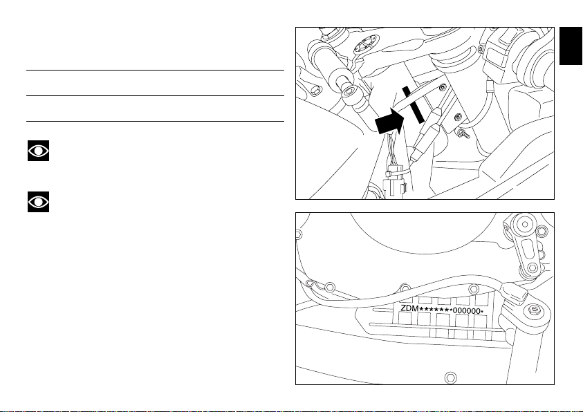
Identification data
All Ducati motorcycles have two identification numbers, one
for the frame (fig. 1) and one for the engine (fig. 2).
Frame number
Engine number
Notes
These numbers indicate the motorcycle model and
should be quoted when ordering spare parts.
Notes
For the 1098 R Bayliss version.
Only a limited a number of this exclusive model will be
produced. Each motorcycle will have a silver plate on the
top yoke indicating the serial number and the model.
E
fig. 1
fig. 2
9
Controls
E
1
Warning
This section shows the position and function of the
controls used to drive the motorcycle. Be sure to read this
information carefully before you use the controls.
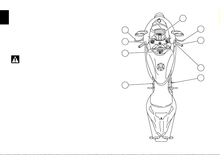
Position of the motorcycle controls (fig. 3)
1) Instrument panel.
2) Key-operated ignition switch and steering lock.
3) Left-hand handlebar switch.
4) Clutch lever.
5) Rear brake pedal.
6) Right-hand handlebar switch.
7) Throttle twistgrip.
8) Front brake lever.
9) Gearchange pedal.
10
4
3
2
9
8
7
6
5
fig. 3
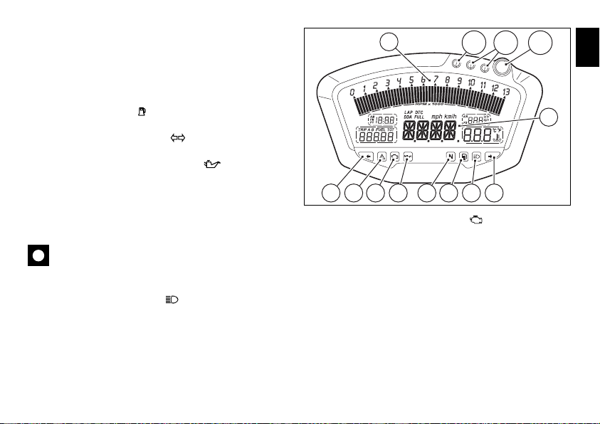
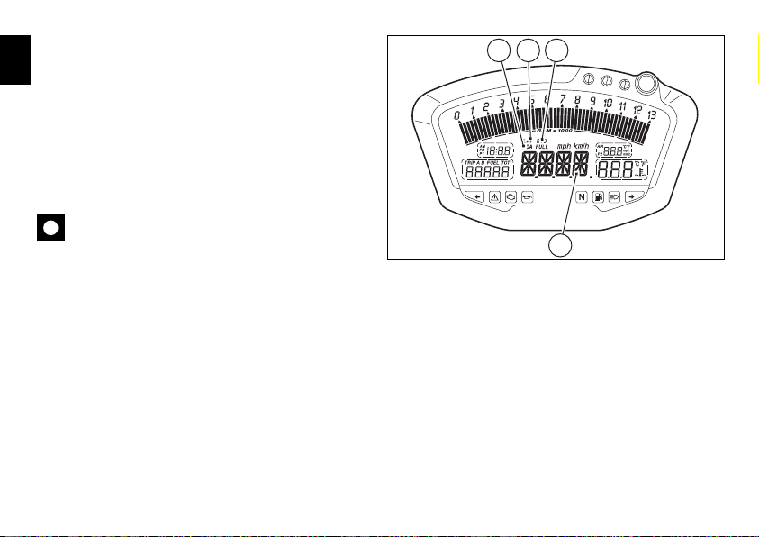
Instrument panel (fig. 4)
1) LCD (see page 13).
2) Tachometer (rpm).
Indicates engine revs per minute.
3) Neutral (N) indicator (green).
Illuminates when the gearbox is in neutral.
4) Fuel warning light (yellow).
Illuminates when there are about 3 litres of fuel left in the tank.
5) Turn signal indicator light (green).
Illuminates and flashes when the turn signal is in operation.
6) Engine oil pressure warning light (red).
Illuminates when engine oil pressure is too low. This light
should illuminate when the ignition is switched to ON and
should go out a few seconds after the engine starts.
It may come on briefly if the engine is very hot, but should
go out again as engine speed increases.
Important
If this light (6) stays on, stop the engine to avoid
serious damage.
7) High beam warning light (blue).
Illuminates when the high beam headlight is on.
2
10B 10C10A
1
5 9 8 6 3 4 57
8) EOBD engine diagnostics light (amber).
The engine ECU illuminates this light to indicate errors and,
in certain cases, consequent engine lockup.
9) “Motorcycle diagnostics” light.
Illuminates when the motorcycle diagnostics detects a
problem.
10) OVER REV- rev limiter indicator lights.
Indicator light 10A: illuminates steadily at 800 rpm before
intervention of the rev limiter.
Indicator lights 10A + 10B: illuminate st eadily 400 rpm before
intervention of the rev limiter.
Indicator lights 10A + 10B + 10C: start flashing when the rev
limiter is reached.
fig. 4
E
11
11) Traction Control light (fig. 5).
Indicator light 11A: with DTC activated, illuminates when
E
minimal torque reduction is applied.
Indicator lights 11A + 11B: with DTC activated, illuminates
when low level torque reduction is applied.
Indicator lights 11A + 11B + 11C: with DTC activated,
illuminates when medium level torque reduction is applied.
Indicator lights 11A + 11B + 11C + 11D: with DTC activated,
illuminates when high level torque reduction is applied.
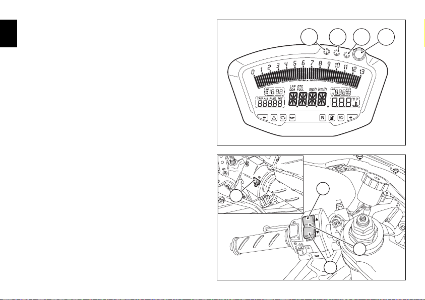
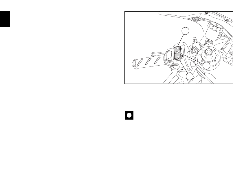
12) 2-position switch A and B (fig. 6).
Switch used for displaying and setting instrument panel
parameters. It has two positions, A “▲” and B “▼”.
13) High beam headlight flasher switch (fig. 6).
The high beam headlight flasher switch is also used for
the LAP and DDA data aquisition functions.
11C11B 11D11A
fig. 5
12
13
A
12
B
fig. 6
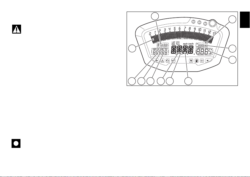
LCD – Main functions
Warning
Any adjustments to the instrument panel must only be
carried out when the motorcycle is stationary. Never operate
the instrument panel controls while riding the motorcycle.
1) Speedometer.
Indicates road speed.
2) Odometer.
Shows total distance travelled.
3) Trip meter.
Shows the distance travelled since the last reset (TRIP A and
TRIP B).
4) Fuel reserve trip counter.
Shows distance travelled on reserve fuel.
5) Clock.
6) Lap time.
7) Rev counter (RPM).
8) Recording of lap time, maximum speed and
maximum rpm (LAP).
9) Battery voltage indicator (BATT).
10) Air temperature indicator.
11) Coolant temperature indicator.
Indicates engine coolant temperature.
Important
Stop riding if the temperature reaches the maximum
value, otherwise the engine might be damaged.
7
2 3 4
5
1 6
9
E
10
11
8
fig. 7
13
12) Servicing indicator (SERV).
The message “SERV” indicates that the service interval has
E
been reached. The message is displayed only at Key-On
for 5 seconds. The service indicator will be reset at an
authorized Ducati Service Centre during servicing.
13) LAP function.
Indicates activation of the LAP function.
14) DDA function.
Indicates activation of the DDA function.
15) Ducati Traction Control (DTC).
Indicates activation of the DTC control unit.
Important
The instrument panel incorporates diagnostic functions
for the electronic injection/ignition system. If you accidentally
access a restricted menu, do not under any circumstances
attempt to use it, but turn the ignition key to OFF. In the
case of any problems, contact an authorized Ducati service
centre to carry outthe necessary checks.
14
151314
12
fig. 8
LCD – How to set/display parameters
At key-on (key turned from OFF to ON) the instrument
panel activates all the digits of the LCD for 1 second and
switches on the indicator lights in sequence.
It then reverts to “normal” mode and, in place of
motorcycle speed, shows the model and, for 2 seconds,
also the version (EU, UK, USA, CND, FRA, JAP).
The model is displayed cyclically until the engine is started.
1098 R vs. EU, UK, CND, FRA, JAP
1098 R Bayliss / 1098 R vs. USA
Notes
If the Ducati Performance kit “Complete Exhaust”
(fig. 58) is installed on the motorcycle, at key-on the
instrument panel will display the message:
ENGINE OFF ENGINE OFF ENGINE OFF ENGINE OFFENGINE OFF ENGINE RUNNING
Warning
The Ducati Performance kit “Complete Exhaust” is
intended for track use ONLY.
E
fig. 9
15
At Key-On, the instrument panel always shows the following
information (de-activating any previously activated functions,
E
with the exception of the Traction Control function):
Odometer
Air temperature
Clock
Speed
Coolant temperature
Engine rpm
At this point, with switch (1, fig. 10) in position B “▼”, it is
possible to switch from the Odometer (TOT) display
function to the following functions:
TRIP A
TRIP B
TRIP FUEL (only if active)
DTC (only available of Ducati Traction Control is both
present and activated) from which the display returns to
the Odometer function (TOT).
If, however, you press switch (1, fig. 10) in position A “▲”,
the system enters MENU mode and displays the
following functions in sequence:
Error (only if at least one error is present)
BATT
RPM
LAP (OFF or ON)
LAP MEM
DDA (OFF or ON)
Erase DDA
DTC OFF/ON (only activated if Traction Control is present)
16
A
1
B
DTC Setup (active only if DTC is activated)
TIME Set
CODE (only if active)
fig. 10
Important
This menu is active only if the speed of the motorcycle
is less than 20 km/h. If this menu is on the display and the
speed of the motorcycle exceeds 20 km/h, the instrument
panel automatically exits the menu and returns to the initial
display. It is possible to exit the menu at any time, however,
by pressing button (1, fig. 10) in position A “▲” for 3 seconds.
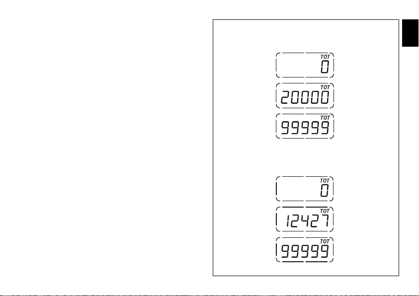
Total distance travelled indicator (odometer)
This function enables display of the total distance travelled.
At Key-On the system automatically enters this function.
The reading is saved permanently and cannot be reset.
If it exceeds 99999 km (or 99999 miles), the reading
“99999” remains displayed permanently.
vs. EU, CND, FRA, JAP
vs. UK, USA
E
fig. 11
17

Air temperature indicator
This function displays the external air temperature.
E
Display limits: -39 °C to +124 °C.
In the event of a sensor FAULT (-40 °C, +125 °C or
disconnected) a series of dashes “- - -” is displayed steadily
and the EOBD engine diagnostics warning light (8, fig. 4)
comes on.
18
vs. EU, UK, CND, FRA, JAP
vs. USA
fig. 12
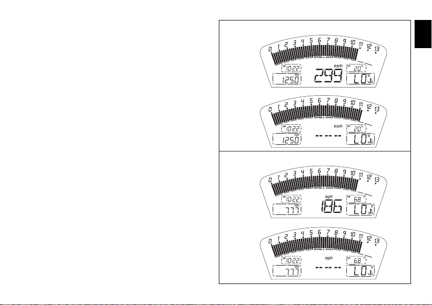
Motorcycle speed
This function displays the motorcycle speed.
The instrument panel receives actual speed value (expressed
in km/h) from the ECU and displays the value increased by 8%.
The maximum speed that can be displayed is 299 km/h
(186 mph).
Over 299 km/h (186 mph) the display will show a series of
dashes “- - -” (steadily lit - not flashing).
vs. EU, CND, FRA JAP
v.s. UK, USA
E
fig. 13
19
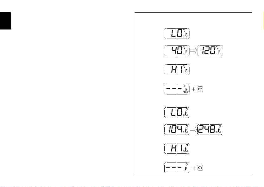
Coolant temperature indicator
Displays the engine coolant temperature:
E
- if the reading is less than or equal to -40 °C (-40 °F), the
display shows a series of flashing dashes (“- - -”) and the
Engine Diagnostics warning light comes on (8, fig. 4);
- if the reading is between -39 °C (-38 °F) and +39 °C
(+102 °F), the message “LO” is displayed steadily;
- if the reading is between +40 °C (+104 °F) and +120 °C
(+248 °F), it is displayed steadily;
- if the reading is between +121 °C (+250 °F) and +124 °C
(+255 °F), the message “HI” flashes on the display;
- if the reading is greater than or equal to +125 °C (+257 °F),
the display shows a series of flashing dashes (“- - -”) and
the EOBD diagnostics warning light (9, fig. 4) comes on.
- In the event of a sensor fault, the display will show a
series of flashing dashes (“- - -”) and the EOBD Engine
Diagnostics light (8, fig. 4) will come on.
vs. EU, UK, CND, FRA, JAP
FIXED DATUM
FIXED DATUM
FLASHING DATUM
FLASHING DATUM
vs. USA
FIXED DATUM
FIXED DATUM
ENGINE
DIAGNOSTICS
20
FIXED DATUM
FLASHING DATUM
FLASHING DATUM
FIXED DATUM
ENGINE
DIAGNOSTICS
fig. 14
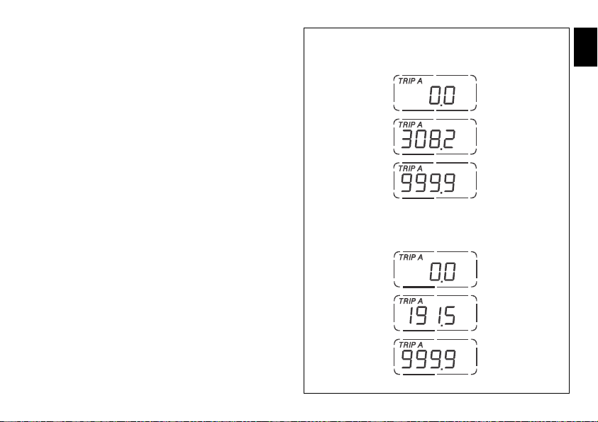
Trip meter “TRIP A”
This function displays the distance travelled since the last
reset.
While in this function, if you press switch (1, fig. 10) in
position B “▼” for 3 seconds, the reading is reset.
If the reading exceeds 999.9, it is reset to zero and the
count restarts automatically.
vs. EU, CND, FRA, JAP
vs. UK, USA
E
fig. 15
21
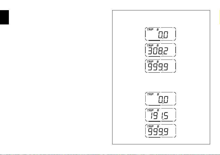
Trip meter “TRIP B”
This function displays the distance travelled since the last
E
reset.
While in this function, if you press switch (1, fig. 10) in
position B “▼” for 3 seconds, the reading is reset.
If the reading exceeds 999.9, it is reset to zero and the
count restarts automatically.
22
vs. EU, CND, FRA, JAP
vs. UK, USA
fig. 16
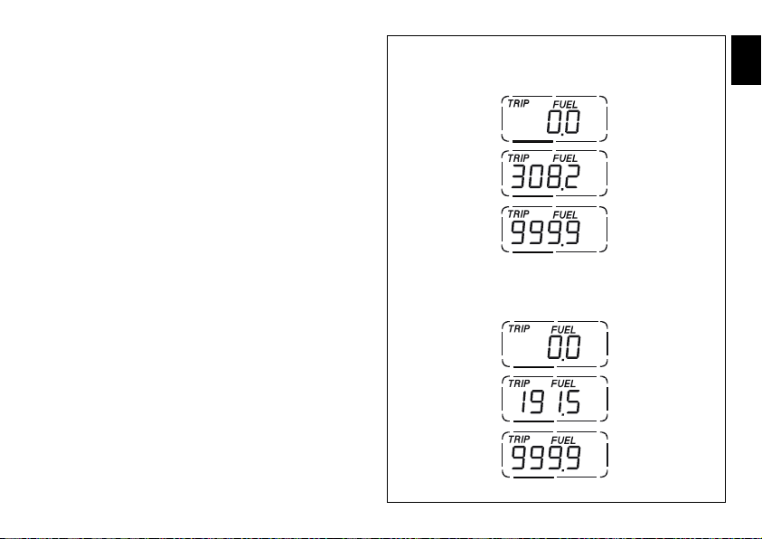
“TRIP FUEL” (distance travelled on reserve fuel)
indicator
This function displays the distance travelled on reserve fuel.
When the fuel warning light comes on, the TRIP FUEL meter
is activated automatically, regardless of the function displayed.
If the fuel level remains in reserve, the reading is saved
even after Key-Off.
The count stops automatically when the fuel level rises
above reserve.
If the reading exceeds 999.9, it is reset and the count
restarts automatically.
vs. EU, CND, FRA, JAP
vs. UK, USA
E
fig. 17
23
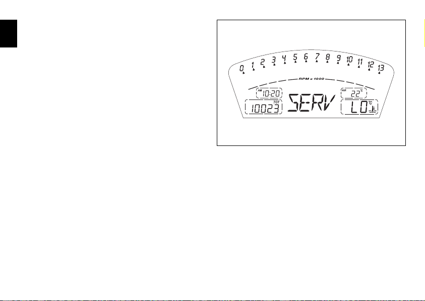
Service indicator (SERV)
Indicates that the next service is due.
E
The message “SERV” appears on the display at the following
intervals:
after the first 1000 km on the odometer;
every 12000 km on the odometer.
The service indicator will remain on the display until reset.
When the message appears, contact your Ducati dealer or
Authorized Service Centre.
24
fig. 18
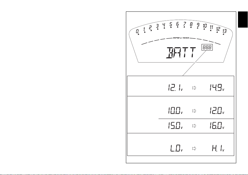
Battery voltage indicator (BATT)
This function displays the battery charge level.
To display this function, go into the menu and select the
“BATT” page.
The battery voltage reading is displayed as follows:
- if the reading is between 12.1 and 14.9 Volts, it is steadily
illuminated on the display;
- if the reading is between 10.0 and 12.0 Volts or between
15.0 and 16.0 Volts, it flashes on the display;
- if the reading is less than or equal to 9.9 Volts, the
message “LO” flashes on the display and the Motorcycle
Diagnostics warning light (9, fig. 4) comes on;
- if the reading is greater than or equal to 16.1 Volts, the
message “HI” flashes on the display and the Motorcycle
Diagnostics warning light (9, fig. 4) comes on.
E
FIXED FIXED
STATUS 1
FLASHING FLASHING
STATUS 2
FLASHING FLASHING
STATUS 3
fig. 19
25
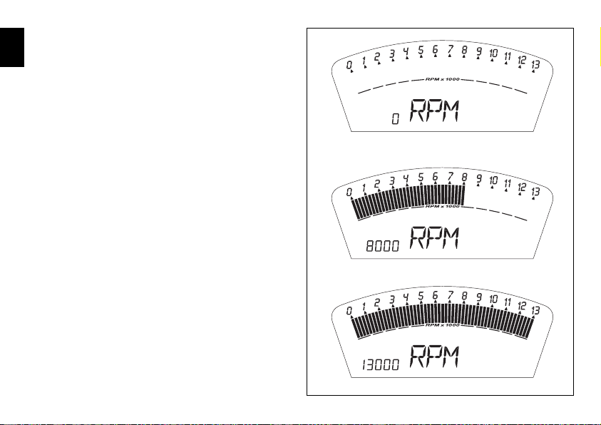
Engine idle speed adjustment (rpm)
This function displays the engine idle speed adjustment.
E
To display the function, access the menu and select the
“RPM” page.
In addition to the upper rev counter scale, the display also
shows engine rpm numerically so that you can adjust the
idle speed more precisely.
26
fig. 20
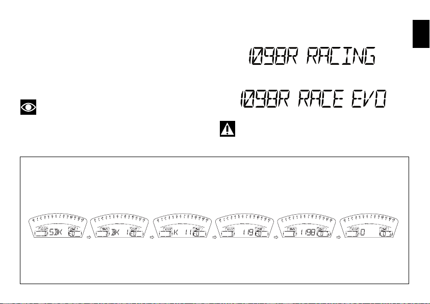
LAP time display function
This function displays the recorded lap time.
To activate this function, go into the menu and set the “LAP”
function to “On” by pressing switch (1, fig. 10) in position B
“▼” for 3 seconds.
START and STOP the timer by pressing the high beam
FLASH button (12, fig. 5) on the left-hand handlebar switch.
When the LAP function is active, each time you press the
flasher switch, the display will show the lap time for
10 seconds, before reverting to normal mode.
You can save a maximum of 30 laps in the memory.
If the memory is full, each time you press the flasher
switch, no more lap times can be saved and the display
will show the flashing message “FULL” for 3 seconds
until the memory is reset.
E
fig. 21
27
When you switch the LAP function off from the menu,
the lap in progress will not be saved.
E
If the LAP function is active and the instrument panel is
suddenly switched off (Key-Off), the LAP function is
switched off automatically (even if the timer was ON,
the lap in progress is not saved).
If the timer is not stopped, when it reaches 99 minutes,
59 seconds and 99 hundredths, it restarts from 0 (zero)
and continues until the function is switched off.
If however the LAP function is switched on and the
memory has not been cleared, but fewer than 30 laps
have been saved (e.g. 18 laps), the instrument panel
will save any remaining laps until the memory is full
(in this case, it will save a further 12 laps).
In this function, lap time only is displayed, but other data are
also saved (MAX speed, MAX rpm, rev limiter if reached)
for viewing at a later date in the Lap Memory function.
28
Press Flash
After 10 secs.
Press Flash
After 10 secs.
fig. 22
LAP Memory display
Displays the data saved using the LAP function: lap time,
MAX speed and MAX rpm.
To display the saved lap times, en ter the menu and select the
“LAP MEM” page.
From this menu page, if you hold pressed switch (1, fig. 10)
in position B “▼” for 3 seconds, the data for the first lap will
appear. The display will show the lap number, lap time, MAX
speed and the MAX rpm reached for the lap in question.
If you press switch (1, fig. 10) in position B “▼”, the display
scrolls through the 30 saved times, before returning to the
st
1
lap.
If you press switch (1, fig. 10) in position B “▼” for
3 seconds while the saved times are displayed, the display
immediately resets all the saved times. In this case, if the
LAP function was active, it is switched off automatically.
The MAX speed saved is the maximum speed indicated
on the display in Lap function.
During saving, if the MAX speed shown exceeds 299 km/h
(186 mph), the speed reached is displayed (e.g. 316 km/h).
If there is no reading in the memory, the 30 times are shown,
with the lap timer showing “00.00.00”, MAX rpm = 0 and
MAX speed = 0.
During the lap, if the engine reaches one of the two
thresholds before the rev limiter or the rev limiter itself,
the respective warning lights (10, fig. 4) come on during
the display of the saved times.
E
B
A
B x 19
A
A
B x 19
A
B
B = ON for 3 secs.
Resets lap times
in memory
B
fig. 23
29

DDA data acquistion
This function serves to activate the DDA (Ducati Data
E
Analyzer)(see page 80): the DDA must be connected to
the motorcycle wiring.
To activate the DDA, go into the menu and set the “DDA”
to “On” by pressing switch (1, fig. 10) in position B “▼” for
3 seconds.
START and STOP the lap separator by pressing the high
beam FLASH button (13, fig. 6) on the left-hand handlebar
switch.
If the DDA function is active and the instrument panel
is suddenly switched off (Key-Off), the function is
automatically disabled.
30
fig. 24

Erase DDA
This function enables you to delete the data saved on the
DDA: the DDA must be connected to the motorcycle wiring.
To delete the data, enter the menu and select the
“Erase DDA” page.
If you press the switch (1, fig. 10) in position B “▼” for
3 seconds and the DDA is not acquiring data, the message
“WAIT…” appears on the display for 10 seconds. After
10 seconds, the message “ERASE OK” appears for
2 seconds, to confirm that the data has been deleted.
If you press the switch (1, fig. 10) in position B “▼” for
3 seconds and the DDA is acquiring data, the DDA
memory is not cleared and the display shows the
message “FAIL” for 2 seconds.
DDA = ON
NO
E
B = On for 3 secs.
YES
Displayed for 2 secs.
Displayed for 10 secs.
Displayed for 2 secs.
fig. 25
31

Function for activation/deactivation of DTC
(Ducati Traction Control)
E
Warning
It is used to activate the Ducati Traction Control
system: DTC.
Warning
Description of the system
DTC is a rider aid that can be used both on the track and the
road.
32
The system is designed to make riding easier and to enhance
safety, but in no way relieves the rider of the obligation to
drive responsibly and to maintain a high standard of riding in
order to avoid accidents, whether caused by his own errors
or those of other road users, through making emergency
manoeuvres, in accordance with the prescriptions of the
highway code.
The rider must always be aware that active safety systems
have a preventive function. The active elements help the
rider control the motorcycle, making it as easy and safe to
ride as possible. The presence of an active safety system
should not encourage the rider to ride at speeds beyond the
reasonable limits, in accordance with the road conditions,
the laws of physics, good riding standards and the
requirements of the highway code.
fig. 26

Activation of the system
To activate the system, the motorcycle must be stationary
and safely parked.
To enable Traction Control, enter the menu and set “DTC”
to “On” by pressing switch (1, fig. 10) in position B “▼” for
3 seconds; once the 3 seconds have elapsed, the message
“DTC” will appear on the display to indicate activation of
the Ducati Traction Control system. When activated, the
message “DTC” is visible both on the normal display and
also within the menu pages.
Notes
The functions of the system
To operate the system, the motorcycle must be stationary
and safely parked.
Each time DTC is activated, the Traction Control ECU will
set the sensitivity level to 8; the level may then be
adjusted using the function “Traction Control Sensitivity
Level Setting (DTC SETUP)”.
To disable Traction Control, enter the menu and set “DTC”
to “OFF” by pressing again switch (1, fig. 10) in position B
“▼” for 3 seconds; once the 3 seconds have elapsed, the
message “DTC” will disappear from the display, thereby
indicating deactivation of the Ducati Traction Control system.
If the engine is suddenly switched off (Key-Off) while
Traction Control is activated, the function will not be disabled
but will still be active (DTC On) at the next Key-ON.
If, however, battery power is suddenly cut off (Batt-OFF),
when battery power is restored and the engine is next
switched on (Key-On), the Traction Control will no longer
be activated (DTC OFF).
Regular maintenance
To ensure that system continues to function correctly it is
necessary to observe the manufacturer’s programmed
maintenance schedule.
Reasonable errors made by the rider with the DTC system
activated.
E
33

DTC (Ducati Traction Control) setting function
This function serves to set the sensitivity level for the DTC
E
(Ducati Traction Control).
To set the Traction Control sensitivity level, with the
motorcycle stationary, enter the “Setup DTC” menu page.
This page only appears in the menu once the Traction
Control ECU has been activated (DTC ON).
The Traction Control sensitivity level setting will be
indicated on the right-hand side of the display (L.1…….L.8);
the levels range from “1” to “8”; the higher the number,
the greater the sensitivity of the Traction Control system
(see following paragraph).
Within this menu page, press switch (1, fig. 10) in position B
“▼” for 3 seconds to access the level setting function.
page 1: the display will show “Setup LEV. 1”.
If you wish to set this level, press switch (1, fig. 10) in
position B “▼”
automatically quit this page and return to the initial display,
with the level setting indicated on the right-hand side.
If instead you wish to set the next highest level, press
switch (1, fig. 10) in position B “▼”.
for 3 seconds; the instrument panel will
Only if
active
B = On for 3 secs.
A
B = ON
for 3 secs.
B A
B = ON
for 3 secs.
B A
34
B
B = ON
for 3 secs.
fig. 27

page 2: the display will show “Setup LEV. 2”.
If you wish to set this level, press switch (1, fig. 10) in
position B “▼”
automatically quit this page and return to the initial display,
with the level setting indicated on the right-hand side.
If you wish to set the next highest level, press switch
(1, fig. 10) in position B “▼”; to return to the previous level,
press switch (1, fig. 10) in position A “▲”.
page 3: the display will show “Setup LEV. 3”.
If you wish to set this level, press switch (1, fig. 10) in
position B “▼”
automatically quit this page and return to the initial display,
with the level setting indicated on the right-hand side.
If you wish to set the next highest level, press switch
(1, fig. 10) in position B “▼”; to return to the previous level,
press switch (1, fig. 10) in position A “▲”.
page 4: the display will show “Setup LEV. 4”.
If you wish to set this level, press switch (1, fig. 10) in
position B “▼”
automatically quit this page and return to the initial display,
with the level setting indicated on the right-hand side.
If you wish to set the next highest level, press switch
(1, fig. 10) in position B “▼”; to return to the previous level,
press switch (1, fig. 10) in position A “▲”.
for 3 seconds; the instrument panel will
for 3 seconds; the instrument panel will
for 3 seconds; the instrument panel will
page 5: the display will show “Setup LEV. 5”.
If you wish to set this level, press switch (1, fig. 10) in
position B “▼”
automatically quit this page and return to the initial display,
with the level setting indicated on the right-hand side.
If you wish to set the next highest level, press switch
(1, fig. 10) in position B “▼”; to return to the previous level,
press switch (1, fig. 10) in position A “▲”.
page 6: the display will show “Setup LEV. 6”.
If you wish to set this level, press switch (1, fig. 10) in
position B “▼”
automatically quit this page and return to the initial display,
with the level setting indicated on the right-hand side.
If you wish to set the next highest level, press switch
(1, fig. 10) in position B “▼”; to return to the previous level,
press switch (1, fig. 10) in position A “▲”.
page 7: the display will show “Setup LEV. 7”.
If you wish to set this level, press switch (1, fig. 10) in
position B “▼”
automatically quit this page and return to the initial display,
with the level setting indicated on the right-hand side.
If you wish to set the next highest level, press switch
(1, fig. 10) in position B “▼”; to return to the previous level,
press switch (1, fig. 10) in position A “▲”.
for 3 seconds; the instrument panel will
for 3 seconds; the instrument panel will
for 3 seconds; the instrument panel will
E
35

page 8: the display will show “Setup LEV. 8”.
If you wish to set this level, press switch (1, fig. 10) in
E
position B “▼”
automatically quit this page and return to the initial display,
with the level setting indicated on the right-hand side.
If you wish to set the next highest level, press switch
(1, fig. 10) in position B “▼”; to return to the previous level,
press switch (1, fig. 10) in position A “▲”.
If DTC is activated, the level setting can also be displayed
outside the page “SEtUP DTC” at the end of the TOT,
TRIP A, TRIP B and TRIP Fuel display functions.
The level setting will remain in memory even after Key-Off.
If, however, battery power is suddenly cut off (Batt-OFF),
when battery power is restored and the engine is next
switched on (Key-On), the Traction Control will no longer
be activated (DTC OFF).
for 3 seconds; the instrument panel will
36
Tips on how to select the sensitivity level
Warning
The 8 DTC level settings have been calibrated using
the same tyres as those originally supplied with your
motorcycle (same make, model and size).
The use of tyres of different size to the original tyres may
alter the operating characteristics of the system.
In the case of minor differences, such as for example,
tyres of a different make and/or model than the original,
but with the same dimensions (rear = 190/55-17; front. =
120/70-17), it may be sufficient simply to select the the
suitable level setting from those available to restore
optimal system operation.
If tyres of a different size class are used or if the tyre
dimensions differ significantly from the original tyres, it
may be that the system operation is affected to the point
where none of the 8 available level settings will give
satisfactory results.
In this case is it is advisable to deactivate the traction control
system.
If level 8 is selected, the DTC control unit will intervene at
the slightest hint that the rear wheel is starting to spin.
Between level 8 and level 1 there are a further 6 intermediate
levels. The level of DTC sensitivity decreases in equal steps
from level 8 to level 1.
When levels 1, 2 or 3 is selected the DTC control unit will
allow the rear wheel to spin and also slide sideways on
exiting a corner; we recommend that this setting is only
used by very experienced riders.

The choice of the correct level depends on 3 main variables:
1) The amount of grip available (type of tyre, amount of
tyre wear, the track surface, weather conditions, etc.).
2) The characteristics of the circuit (bends all taken at
similar speeds or at very different speeds).
3) The riding style (whether the rider favours a more
“rounded” or a more “angular” style).
The relation of the DTC sensitivity level to grip conditions:
The choice of level setting depends greatly on the grip
conditions of the track/circuit (see below, tips for use on
the track and on the road).
The relation of the DTC sensitivity level to the circuit
characteristics:
If all the corners on the track/circuit can be taken at a similar
speed, it will be easier to find an intervention level that is
satisfactory for every bend; on the other hand, if the track
has, for example, one corner that is much slower than all
the others, it will necessary to find a compromise level
(on the slow corner the DC will tend intervene more than
on the faster corners).
The relation of the DTC sensitivity level to riding style:
The DTC will tend to intervene more with a “rounded”
riding style, where the bike is leaned over further, rather
than with an “angular” style, where the bike is straightened
up as quickly possible on exiting a corner.
Tips for use on the track
We recommend that level 8 is used for a couple of full laps
(to allow the tyres to warm up) in order to get used to the
system. Then try levels 7, 6, etc, in succession until you
identify the DTC sensitivity level that suits you best
(always try each level for at least two laps to allow the
tyres to warm up).
Once you have found a satisfactory setting for all the corners
except one or two slow ones, where the system tends to
intervene too much, you can try to modify your riding style
slightly to a more “angular” approach to cornering i.e.
straighten up more rapidly on exiting the corner, instead
of immediately trying a different level setting.
Tips for use on the track
Activate the DTC, select level 8 and ride the motorcycle in
your usual style; if the level of DTC sensitivity seems
excessive, try reducing the setting to level 7, 6, etc., until
you find the level that suits you best.
If changes in the grip conditions and/or circuit characteristics
and/or your riding style, and the level setting is no longer
suitable, switch to the next level up or down and proceed as
described above to determine the best setting (e.g. if with
level 7 the DTC sensitivity seems excessive, switch to
level 6; alternatively, if on level 7 you cannot perceive any
DTC intervention, switch to level 8).
E
37

Clock setting function
This function is used to set the clock time.
E
To set the clock, enter the menu and select the “TIME Set”
page.
From this page, if you press switch (1, fig. 10) in position B
“▼” for 3 seconds, you enter clock setting mode.
On entering this function, the message “AM” flashes on
the display; on pressing switch (1, fig. 10) in position B “▼”
the message “PM” will start to flash:
pressing switch (1, fig. 8) in position B “▼” returns you to
previous step (if the time is 00:00, on switching from AM
to PM, the display will show 12:00);
if you press switch (1, fig. 10) in position A “▲”, you pass
to the hours setting mode and the hours digits will start
flashing. Each time you press the switch in position B “▼”,
the count advances cyclically in steps of 1 hour; if you hold
the switch down in position B “▼”, the count advances
cyclically in steps of 1 hour every second (when the switch
is held down continuously, the hours do not flash);
if you press switch (1, fig. 10) in position A “▲”, you enter
the minutes setting mode and the minute digits will start
flashing. Each time you press the switch in position B “▼”,
the minutes increase cyclically in steps of 1 minute; hold the
switch pressed in position B “▼” to scroll faster through the
minutes in steps of 1 minute every second. If the switch is
held pressed in position B “▼” for more than 5 seconds, the
minutes advance by 1 every 100 ms (when the switch is held
in position B “▼” continuously, the seconds do not flash);
if you press the switch in position A “▲”, the system
exits setting mode and displays the newly set time.
38
B = ON for 3 secs.
Flashing
B
Flashing
B
Flashing
B
Flashing
B
B
B
A
A
A
A
Flashing
A
Flashing
A
fig. 28

Instrument panel diagnostics
Important
The instrument runs the system diagnostics correctly
60 seconds after the last Key-Off.
Any errors detected in the behaviour of the motorcycle are
displayed.
If there are several errors, they are displayed in rolling mode
every 3 seconds.
The table below shows the errors that can be displayed.
Warning light Error message Error
COIL 8.1 Horizontal cylinder coil error
COIL 8.2 Horizontal cylinder coil error
COIL 9.1 Vertical cylinder coil error
COIL 9.2 Vertical cylinder coil error
COIL 10.1 Horizontal cylinder coil error
COIL 10.2 Horizontal cylinder coil error
COIL 11.1 Vertical cylinder coil error
Warning
Every time an error is displayed, always contact an
authorized Ducati Service Centre.
E
39

Warning light Error message Error
E
COIL 11.2 Vertical cylinder coil error
INJE 12.1 Horizontal cylinder injector error
INJE 12.2 Horizontal cylinder injector error
INJE 13.1 Vertical cylinder injector error
INJE 13.2 Vertical cylinder injector error
INJE 14.1 Horizontal cylinder injector error
INJE 14.2 Horizontal cylinder injector error
INJE 15.1 Vertical cylinder injector error
INJE 15.2 Vertical cylinder injector error
PUMP 16.0 Fuel pump relay error
FAN 18.1 Fan relay error
FAN 18.2 Fan relay error
40

Warning light Error message Error
STRT 19.1 Starter contactor error
STRT 19.2 Starter contactor error
STEP. 21.1 Stepper motor error
STEP. 21.2 Stepper motor error
STEP. 21.3 Stepper motor error
LAMB. 22.1 Lambda heater error
LAMB. 22.2 Lambda heater error
EXVL 23.1 Exhaust valve motor error
EXVL 23.2 Exhaust valve motor error
EXVL 23.3 Exhaust valve motor error
EXVL 23.4 Exhaust valve motor error
TPS 1.1 Throttle position sensor error
E
41

Warning light Error message Error
E
TPS 1.2 Throttle position sensor error
PRESS 2.1 Pressure sensor error
PRESS 2.2 Pressure sensor error
T.WAT 3.1 Engine coolant temperature sensor error
T.WAT 3.2 Engine coolant temperature sensor error
AIR 4.1 Air temperature sensor error
AIR 4.2 Air temperature sensor error
BATT 5.1 Battery voltage error
BATT 5.2 Battery voltage error
LAMB 6.1 Lambda sensor error
TILT 6.2 Lambda 2 sensor error
DTC 8.0 Traction control ECU error
42

Warning light Error message Error
ECU 30.0 Engine ECU error
PK.UP 34.0 Pick-up sensor error
SPEE. 36.0 Speed sensor error
IMMO 37.0 Immobilizer error
IMMO 37.1 Immobilizer error
IMMO 37.3 Immobilizer error
IMMO 37.5 Immobilizer error
CAN 38.0 CAN line error
E
43

Display backlight
The instrument panel backlighting is always activated at key-
E
ON. The instrument panel is equipped with internal sensors
that detect the ambient light level and at night reduces the
maximum backlighting level by 20% to prevent glare.
Intelligent headlight switch-off
This function helps reduce battery use by automatically
switching off the headlight. The device is triggered in
3 cases:
- in the first case, if you turn the key from OFF to ON
and do not start the engine within 60 seconds, the
headlight is turned off and will be turned on again
only when the engine is next switched on;
- in the second case, after normal use of the vehicle with
the lights on, if the engine is killed via the RUN-STOP
button on the RH switch.
In this case, the headlight is switched off 60 seconds
after the engine is switched off, and only switched on
again the next time the engine is started;
- in the third case, the headlight is switched off while
the engine is being started and switched back on again
when the engine is running.
44
Intelligent headlight switch-on
This function allows programmed activation of the headlight
even with the motorcycle off (Key-Off).
Immediately after key-off, the instrument panel remains
active for 60 seconds, thus allowing the headlight to be
switched on if switch (1, fig. 10) is pressed in position A “▲”
or B “▼”.
During these 60 seconds, each time switch (1, fig. 10) is
pressed in position A “▲” or B “▼”, the instrument panel
will activate the headlight for 30 seconds; each press of
switch (1, fig. 10) in position A “▲” or B “▼” will add to the
headlight activation time, up to a maximum of 6 presses
(equivalent to a maximum activation time of 180 seconds).
After the first time you press switch (1, fig. 10) in position A
“▲” or B “▼”, the period of 30 seconds starts, thus
switching on the headlight. Further switch-on time can be
added only if you press the switch again within these
30 seconds. If the 30 seconds have elapsed, no further
multiples of 30 seconds can be added, and the instrument
panel will switch off the headlight.
To reset this function, you must perform at least one Key-On/
Key-Off.
If the battery power is interrupted at any time while this
function is active, when power is restored, the instrument
panel will de-activate the function (the instrument panel
does not remain active for 60 seconds).

The immobilizer system
For additional anti-theft protection, the motorcycle is
equipped with an IMMOBILIZER, an electronic system
that locks the engine automatically whenever the ignition
switch is turned off.
The grip of each ignition key contains an electronic device
that modulates the output signal from a special antenna
in the switch when the ignition is switched On. The
modulated signal represents the “password” (which is
changed at each start-up) by which the ECU recognizes
the ignition key. The ECU will only allow the engine to
start if it recognises this password.
Keys
(fig. 29)
The owner receives a set of keys, comprising:
- 2 black keys (B).
These contain the “code” of the immobilizer system.
Notes
The two keys have a small tag (1) attached, which
shows their identification number.
Warning
Keep the keys separate, and store the tags (1) in a safe
place.
It is also advisable to use only one of the black keys to start
the motorcycle.
E
Notes
Your Ducati dealer may ask you to produce your Code
Card in order to carry out certain servicing operations.
The black keys (B) are the keys for normal use, and are used
to:
- start the engine;
- open the lock on the fuel tank filler cap;
- open the seat lock.
B
1
fig. 29
45

Code card
A CODE CARD (fig. 30) is supplied with the keys, showing
E
the electronic code (A, fig. 31) that must be used if the
engine is locked by the immobilizer and consequently
does not start at the next Key-On.
Warning
Keep the CODE CARD in a safe place. We advise the
user to keep the code printed on the CODE CARD on his/her
person at all times in order to be able to override the engine
lock using the procedure described below, in the event of
a malfunction of the immobilizer system, signalled by
illumination of the amber diagnostic light (9, fig. 4).
This operation is only possible if the electronic code
indicated on the code card is known.
Warning
Your dealer will ask you to produce the Code Card
in order to re-program or replace a key.
46
fig. 30
A
fig. 31

Immobilizer override procedure
Should the immobilizer become locked, you can perform
the “Immobilizer Override” procedure from the instrument
panel by entering the respective function as follows:
select the “CODE” page from the menu.
E
Notes
This menu should be active only if there is at least one
immobilizer error.
With this menu page selected, the initial code is always
displayed as “00000”. If you hold the button (1, fig. 10) in
position B “▼” for 3 seconds, you will access the procedure
for entering the electronic code given on the Code Card.
B = ON for 3 secs.
B
B
B
B
B
B
B
B
B
A
A
A
A
A
No
Yes
Code
OK?
fig. 32
47

Entering the code:
on entering this function, the first digit on the left starts
E
flashing.
Switch (1, fig. 10):
each time you press the switch in position B “▼”, the
number increases cyclically in steps of one digit every
second;
if you press the switch in position A “▲”, you can set
the second digit, which will start flashing. Each time you
press the switch in position B “▼”, the number increases
cyclically in steps of one digit every second;
if you press the switch in position A “▲”, you can set the
third digit, which will start flashing. Each time you press
the switch in position B “▼”, the number increases
cyclically in steps of one digit every second;
if you press the switch in position A “▲”, you can set the
fourth digit, which will start flashing. Each time you press
the switch in position B “▼”, the number increases
cyclically in steps of one digit every second;
if you press the switch in position A “▲”, you can set the
fifth digit, which will start flashing. Each time you press
the switch in position B “▼”, the number increases
cyclically in steps of one digit every second;
press in position A “▲” to confirm the code.
48
If the code has been entered correctly, the message CODE
and the code itself will flash simultaneously for 4 seconds.
The motorcycle diagnostics warning light (9, fig. 4) will switch
off. The instrument panel then automatically exits the menu,
thus temporarily allowing the motorcycle to be started.
If the error persists, at the next key-on, the instrument panel
will return to an error state and immobilize the engine.
If the code has been entered incorrectly, however, the
instrument panel will automatically return to the “CODE”
menu and display the code “00000”.

Operation
When the ignition key is turned from ON to OFF, the
immobilizer system activates the engine lock. When the
ignition key is turned from OFF to ON to start the engine:
1) if the code is recognised, the protection system releases
the engine lock. When you press the START (2, fig. 36)
switch, the engine will start up;
2) if the motorcycle diagnostics warning light (9, fig. 4)
comes on and if, when you press switch (1, fig. 10) in the
position B “▼”, the “Error IMMO” message appears on the
display, indicating that the code has not been recognised.
In this case, turn the ignition key back to OFF and then to
ON again. If the engine still does not start, try again with the
other black key. If the engine still does not start, contact
the DUCATI Service network.
Warning
Sharp knocks can damage the electronic components
inside the key.
Always use the same key throughout the procedure. Using
different keys could prevent the system from recognising
the code in the key.
Duplicate keys
If you need additional keys, contact your DUCATI Service
Centre with all the keys you have in your possession and
your CODE CARD.
The Ducati Service Centre will program all the new keys as
well as any keys you already have.
You may be asked to provide proof that you are the
legitimate owner of the motorcycle.
The codes for any keys not present during the memory
programming procedure are cancelled, to ensure that
any keys that may have been lost can no longer be used
to start the engine.
Notes
If you sell your motorcycle, do not forget to pass on
all the keys and the CODE CARD to the new owner.
E
49

Ignition switch and steering lock (fig. 33)
This is located in front of the fuel tank and has four positions:
E
A) ON: enables lights and engine operation;
B) OFF: disables lights and engine operation;
C) LOCK: the steering is locked;
D) P: parking light on and steering locked.
Notes
To move the key to the latter two positions, push it
in before turning. The key can be removed in positions (B),
(C) and (D).
50
A
B
C
D
fig. 33

Left-hand handlebar switch (fig. 34)
1) Dip switch, two-position light selector switch:
position = low beam headlight on;
position = high beam headlight on.
2) Switch = three-position turn signal:
centre position = off;
position = left turn;
position = right turn.
To cancel the indicator, press the lever once it has returned
to the central position.
3) Button = horn.
4) Switch = high beam flasher and instrument panel
control.
5) Two-position instrument panel control switch:
position “▲”;
position “▼”.
E
4
1 2
3 5
fig. 34
51

Clutch lever
The lever (1) disengages the clutch. The span adjuster (2)
E
serves to alter the distance of the lever from the handlebar.
Lever distance is adjusted by 10 clicks of the knob (2).
Turn the knob clockwise to move the lever away from
twistgrip, or anti-clockwise to move it closer.
When the clutch lever (1) is operated, drive from the
engine to the gearbox and the rear wheel is disengaged.
Correct use of the clutch lever is very important in all
riding situations, especially when moving off.
Warning
Any adjustment of clutch lever must be carried out
when motorcycle is stationary.
Important
Using the clutch properly will prolong the life of the
engine and prevent any damage to components in the
transmission.
Notes
The engine can be started with the sidestand down
and the gearbox in neutral. When starting the engine with
a gear engaged, pull in the clutch lever (in this case the
sidestand must be in the raised position).
52
2 1
fig. 35

Right-hand handlebar switch (fig. 36)
1) Two-position ENGINE STOP switch:
position (RUN) = run;
position (OFF) = stop engine.
Warning
This switch is mainly intended for use in
emergencies when you need to stop the engine quickly.
After stopping the engine, return the switch to the
position to start the engine.
Important
After travelling with the lights on, if the engine is
switched off using switch (1) and the ignition key is left in
the ON position, the battery can be drained since the
headlamp remains on.
2) Button = engine start.
Throttle twistgrip (fig. 36)
The twistgrip (3) on the right handlebar opens the butterfly
valves in the throttle body. When released, the twistgrip
returns automatically to the initial position (idling speed).
E
3
1
2
fig. 36
53

Front brake lever (fig. 37)
Pull the lever (1) towards the twistgrip to operate the
E
front brake. The system is hydraulically assisted and you
only need to pull the lever gently.
The brake lever (1) has a knob (2) for adjusting the distance
between lever and twistgrip on the handlebar.
Lever distance is adjusted by 10 clicks of the knob (2).
Turn the knob clockwise to move the lever away from
twistgrip, or anti-clockwise to move it closer.
54
21
fig. 37

Rear brake pedal (fig. 38)
Push down on the pedal (1) with your foot to operate the
rear brake.
The system is controlled hydraulically.
1
fig. 38
E
Gearchange pedal (fig. 39)
The gear change pedal is at rest when in centre position N,
and automatically returns to the centre position. When in this
position, light N (3, fig. 4) on instrument panel comes on.
The pedal can be moved:
downwards = push down on the pedal to engage 1
and to shift down. At this point the N light on the instrument
panel will go off;
upwards = lift the pedal to engage 2
th
5
and 6th gears.
Each time you move the pedal you engage the next gear,
one gear at a time.
nd
gear and then 3rd, 4th,
st
gear
6
5
4
3
2
N
1
fig. 39
55

Adjusting the position of the gearchange
E
and rear brake pedals (fig. 40 and fig. 41)
The position of the gearchange and rear brake pedals in
relation to the footrests can be adjusted to suit the
requirements of the rider.
To adjust the position, proceed as follows:
restrain the tie-rod (1) and slacken the locknuts (2) and (3).
Notes
The locknut (2) has a left-hand thread.
Turn the tie-rod (1) using an open-ended wrench on the flats
to move the gearchange pedal to the required position.
Tighten both locknuts onto the rod.
56
2 1 3
fig. 40

To adjust the position of the rear brake pedal, proceed as
follows:
Loosen the locknut (4).
Turn the pedal travel adjustment bolt (5) until the pedal is in
the desired position.
Tighten the locknut (4) to a torque of 2.3 Nm.
Operate the pedal by hand to check that there is 1.5 to 2 mm
of freeplay before the brake bites.
If not, adjust the length of the master cylinder pushrod as
follows:
Slacken off the locknut (6) on the pushrod.
Screw the rod into the clevis (7) to increase play, or unscrew
it to reduce play.
Tighten the lock nut (6) to a torque of 7.5 Nm and re-check
the free play.
7
6
E
4
5
fig. 41
57

Main components and
E
devices
Position on motorcycle (fig. 42)
1) Fuel tank filler cap.
2) Catalytic converter.
3) Sidestand.
4) Steering damper.
5) Rearview mirrors.
6) Front fork adjusters.
7) Rear shock absorber adjusters.
8) Suspension tie-rod for adjustment of rear ride height.
9) Exhaust silencer (see note on page 74).
58
92
6
5
7
6
4
8
3
15
fig. 42

Fuel tank filler cap (fig. 43)
Opening
Raise the cover (1) and insert the key into the lock.
Give the key a 1/4 turn clockwise to unlock.
Lift the cap.
Closing
Close the cap with the key inserted and push it into its seat.
Turn the key anticlockwise to the initial position and remove
it. Replace the lock cover (1).
Notes
The cap can only be closed with the key inserted.
Warning
Always make sure you have properly closed the
fuel filler cap after refuelling (see page 75).
E
1
fig. 43
59

Sidestand (fig. 44)
E
Important
Before lowering the sidestand, check that the ground
is sufficiently even and firm.
Do not park on soft ground, gravel or on asphalt softened
by the sun etc. or the motorcycle may fall over.
When parking on a slope, always park with the rear wheel
on the downhill side.
To lower the sidestand, hold the motorcycle handlebars
with both hands and, with your foot, push down the stand (1)
until fully extended. Tilt the motorcycle until the sidestand
is resting on the ground.
Warning
Do not sit on the motorcycle when it is supported on
the sidestand.
To raise the sidestand to rest position (horizontal), tilt the
motorcycle to the right and, at the same time, lift the
stand (1) with your foot.
60
Notes
It is advisable to check periodically that the stand
mechanism (consisting of two springs, one inside the other)
and safety sensor (2) are working properly.
Notes
The engine can be started with the sidestand down
and the gearbox in neutral. If starting with a gear engaged,
pull in the clutch lever (in this case the sidestand must be up).
2
1
fig. 44

Steering damper (fig. 45)
The steering damper is located in front of the tank and
secured to the frame and the top yoke.
The damper helps improve steering precision and stability,
and thus also improves ride quality in all riding conditions.
Turn the knob (1) clockwise to obtain a stiffer damping
action or anticlockwise to soften it.
Each adjustment position is identified by a click.
Warning
Never attempt to adjust the knob (1) while riding, or
you may lose control of the motorcycle.
1
fig. 45
E
61

Front fork adjusters
The front fork can be adjusted for rebound, compression and
E
spring preload.
The settings are adjusted by way of external adjuster screws:
1) to adjust rebound damping (fig. 46);
2) to adjust inner spring preload (fig. 46);
3) to adjust compression damping (fig. 47).
Park the motorcycle in a stable position on its sidestand.
To adjust the rebound damping setting, turn the adjuster (1)
on the top of each fork leg using the special wrench.
As you turn the adjuster (1), you will hear it click. Each click
corresponds to a setting. The maximum damping is obtained
with the adjuster screwed in fully to the “0” position.
Start with this position and turn counterclockwise. Count
the clicks, which correspond to position 1, 2 and so forth.
62
1
2
fig. 46

The STANDARD factory settings are as follows:
compression: 8 clicks;
rebound: 10 clicks.
Spring preload: with the adjuster FULLY SCREWED OUT,
screw in (clockwise) 8 turns; this corresponds to a spring
preload of 8 mm.
To change the spring preload for each fork leg, turn the
adjuster (2, fig. 46) with a 22 mm hex wrench.
Important
Adjust both fork legs to the same setting.
3
fig. 47
E
63

Rear shock absorber adjusters (fig. 48)
The shock absorber has external adjusters that enable you to
E
adjust the suspension to suit the load on the motorcycle.
The two adjusters on the shock absorber reservoir serve
to adjust the compression damping (1 – gold) and the
rebound damping (2 - black).
Turn the adjusters (1 and 2) clockwise to stiffen the
damping or anti-clockwise to soften it.
STANDARD setting:
from the fully closed position (turned fully clockwise), unscrew:
adjuster (1) by 14 clicks;
adjuster (2) by 14 clicks.
Spring preload: 19 mm.
The two nuts (3) on the upper part of the shock absorber
serve to adjust the preload on the external spring. To
change spring preload, slacken off the upper lock nut.
Then tighten or loosen the lower nut to increase or
decrease spring preload as required.
64
1
2
3
fig. 48

Once the desired spring preload has been set, re-tighten the
upper lock nut.
Warning
Use a pin wrench to turn the preload adjusting nut. Take
special care when turning the nut, to avoid injuring your hand
by striking it violently against other parts of the motorcycle if
the wrench suddenly slips off the nut while turning.
Warning
The shock absorber is filled with gas under pressure
and may cause severe damage if taken apart by unskilled
persons.
If you plan to carry luggage, adjust the rear shock absorber
spring load to the maximum setting to improve the
handling characteristics of the motorcycle and to avoid the
possibility of ground contact. It may also be necessary to
adjust the rebound damping accordingly.
E
65

Adjusting the rear ride height (fig. 49, fig. 50
E
and fig. 51)
The standard ride height setting is the result of rigorous
testing carried out in a wide variety of conditions by our
technical staff.
Modifying the ride height is a very critical operation, and can
be dangerous if carried out by untrained persons.
Before changing the standard setting, measure the
reference value (H, fig. 49).
The rider can adjust the rear ride height to suit his/her needs
by changing the working position of the rear shock absorber.
To alter the eye to eye length of the tie-rod (1), slacken the
locknuts (3).
Notes
Note that the lower nut (3) has a left-hand thread.
Use an open-end wrench on the flats (4) of the tie-rod (2).
Once the tie-rod length is adjusted correctly, tighten the
nuts (3) to 25 Nm.
Warning
The length of the tie-rod (2) between the centres of
the two eyes (1) should not exceed 285 mm.
66
H
fig. 49
1
3
2
4
3
1
fig. 50

The maximum distance that the UNIBALL end fitting (A)
can be unscrewed from the tie-rod body is 5 threads, or
7.5 mm (B).
B
E
A
fig. 51
67

Riding the motorcycle
E
Running-in precautions
Max. rpm (fig. 52)
Rpm limits to be observed during the running-in period and in
normal use:
1) up to 1000 km;
2) from 1000 to 2500 km.
Up to 1000 km
During the first 1000 km, keep an eye on the tachometer.
The revs should never exceed 5.500÷6000 rpm.
During the first hours of riding, it is advisable to continuously
vary the load on the engine and the rpm, though still keeping
within the above limits.
For this reason, roads with numerous bends and hilly areas
are ideal for running in the engine, brakes and suspension.
For the first 100 km, use the brakes gently. Do not brake
violently or keep brake applied for too long. This will enable a
correct break-in of friction material on brake pads against
brake discs.
68
To allow all the mechanical moving parts in the motorcycle to
adapt to one another, and to avoid shortening the life of the
main engine components, it is advisable to avoid sudden
acceleration and running the engine at high rpm for too long,
especially uphill.
It is also advisable to check the drive chain frequently and
ensure that it is lubricated as required.

From 1000 to 2500 km
At this point, you can ask for more power from the engine,
being careful, however, never to exceed 7000 rpm.
Important
Throughout the running-in period, be careful to stick to
the recommended maintenance schedule and periodic service
intervals indicated in the warranty booklet. Failure to follow
these instructions releases Ducati Motor Holding S.p.A. from
any liability whatsoever for any engine damage or shorter
engine life.
Keeping to the running-in recommendations will ensure
longer engine life and reduce the need for overhauls and
re-tuning.
0 ÷ 1000 Km
1000 ÷ 2500 Km
E
fig. 52
69

Pre-ride checks
E
Warning
Failure to carry out these checks before starting may
result in damage to the motorcycle and injury to rider.
Before starting, check the following points:
Fuel level in the tank
Check the fuel level in the tank. Re-fuel if necessary (page 75).
Engine oil level
Check the oil level in the sump through the sight glass.
Top up if necessary (page 103).
Brake and clutch fluid
Check the fluid levels in the respective reservoirs (page 87).
Coolant
Check coolant level in the expansion reservoir. Top up if
necessary (page 86).
Tyre condition
Check the pressure and condition of the tyres (page 101).
Controls
Operate the brake, clutch, throttle and gear change controls
(levers, pedals and twistgrip) to check that they function
correctly.
Lights and indicators
Make sure the lights, indicators and horn work properly.
Replace any burnt-out bulbs (page 95).
70
Key locks
Check that the fuel filler cap (page 59).
Sidestand
Make sure sidestand operates smoothly and is in the correct
position (page 60).
Warning
If there are any faults or malfunctions, do not start
the motorcycle and contact your DUCATI Dealer or
Authorized Service Centre.

Starting the engine
Warning
Before starting the engine, familiarise yourself with
the controls that you will use when riding (page 10).
Warning
Never start or run the engine in enclosed space.
Exhaust gases are toxic and may lead to loss of
consciousness or even death within a short time.
1) Turn the ignition key to ON (fig. 53). Check that both
the green light N and the red light on the instrument
panel come on.
Important
The oil pressure warning light should go out a few
seconds after the engine has started (page 11).
Warning
The sidestand should be in rest position (horizontal),
otherwise the safety sensor prevents the engine starting.
E
fig. 53
71

Notes
E
The engine can be started with the sidestand down
and the gearbox in neutral. If starting with a gear engaged,
pull in the clutch lever (in this case the sidestand must be up).
2) Check that the stop switch (2, fig. 54) is positioned to
(RUN), then press the starter button (3, fig. 54).
Important
Do not rev the engine when cold. Allow some time for
the oil to warm up and reach all points that need lubricating.
72
2
3
fig. 54

Moving off
1) Disengage the clutch by squeezing the clutch lever.
2) Push down the gearchange lever firmly with the tip of
your foot to engage first gear.
3) Raise the engine revs by turning the throttle twistgrip
while gradually releasing the clutch lever. The motorcycle
will start moving.
4) Release the clutch lever completely and accelerate.
5) To change up to the next gear, close the throttle to
reduce the engine revs, disengage the clutch, lift the
gearchange lever and release the clutch lever.
To change down, proceed as follows: release the twistgrip,
disengage the clutch, briefly rev the engine to allow the
gears to synchronize, shift down and release the clutch lever.
Use the controls intelligently and opportunely: when riding
uphill, do not hesitate to shift down as soon as the
motorcycle starts to slow down, so you will avoid
overloading the engine and putting too much strain on
the the motorcycle generally.
Important
Avoid sudden acceleration, as this may lead to
misfiring and transmission snatching. The clutch lever should
not be held in longer than necessary after a gear is engaged,
otherwise friction parts may overheat and wear out.
Braking
Slow down in time, change down to use the engine brake,
then apply both brakes. Pull in the clutch lever before the
motorcycle comes to a stop to prevent the engine stalling.
Warning
Use both the brake lever and the brake pedal for
effective braking. Using only one of the brakes will give
you less braking power.
Never use the brake controls harshly or suddenly as you
may lock the wheels and lose control of the motorcycle.
When riding in the rain or on slippery surfaces, braking
capacity is significantly reduced. Always use the brakes
very gently and carefully when riding under these conditions.
Any sudden manoeuvres may lead to loss of control.
When riding down long, steep downhill slopes, change down
to use engine braking. Apply the brakes intermittently for
brief periods only. Keeping the brakes applied continuously
causes the friction material to overheat and dangerously
reduces braking effectiveness. Under-inflated or overinflated tyres reduce braking efficiency and may adversely
affect safe riding and road-holding on bends.
E
73

Stopping the motorcycle
Reduce speed, change down and release the throttle twistgrip.
E
Change down to engage first gear and then neutral. Apply
the brakes and bring the motorcycle to a complete stop.
Switch the engine off by turning the key to OFF (page 50).
Parking
Stop and park the motorcycle on the sidestand
(see page 60).
To prevent theft, turn the handlebar fully left and turn
the ignition key to the LOCK position.
If you park in a garage or other indoor area, make sure
that there is proper ventilation and that the motorcycle is
not near a source of heat.
If necessary, you can leave the sidelights on by turning the
key to position P.
Important
Do not leave the key at P for long periods or the
battery will run down. Never leave the motorcycle
unattended with the ignition key inserted.
Warning
The exhaust system might be hot even after engine
is switched off; take special care not to touch the exhaust
system with any part of your body and do not park the
motorcycle next to inflammable material (wood, leaves, etc.).
74
Warning
Using padlocks or other locks designed to prevent
movement of the motorcycle (such as brake disc locks, rear
sprocket locks, and so on) is very dangerous, and may impair
motorcycle operation and the safety of rider and passenger.

Refuelling (fig. 55)
Do not overfill the tank when refuelling. The fuel level
should always be below the rim of the filler recess.
Warning
Use fuel with low lead content and an original octane
number of 95 minimum (see table “Fluids and lubricants”
on page 112).
Check that no fuel is trapped in the filler cap recess.
Max level
E
fig. 55
75

Accessories supplied (fig. 56 and fig. 57)
The compartment behind the seat, which can be
E
accessed through the seat back (A), houses:
use and maintenance manual;
toolkit consisting of:
- spark plug wrench;
- tommy bar for spark plug wrench;
- double-ended screwdriver;
- Allen key for fairing panels.
To open the seat back, turn the fastener (B) anti-clockwise
to release it.
To close the seat back, turn the fastener clockwise until it
engages.
B
A
Notes
A seat lock (C) is also supplied so that the motorcycle
may be converted from single seat to dual seat: to do this,
contact an Authorized Ducati Service Centre.
76
fig. 56
C
fig. 57

The 1098 R version is supplied with:
- carbon fibre silencers (1, fig. 58);
- dedicated ECU (2, fig. 58).
The 1098 R USA version is supplied with:
- carbon fibre silencers (1, fig. 58);
- dedicated ECU (2, fig. 58);
- central exhaust pipe (3, fig. 58).
vs. EU, UK, CND, FRA, JAP
1
E
2
vs. USA
2
1
1
1
3
fig. 58
77

The 1098 R Bayliss version is supplied with:
- numbered identification plaque (3, fig. 59);
E
- rear paddock stand (4, fig. 59);
- bag (5, fig. 59);
- bike cover (6, fig. 59);
- carbon fibre silencers (7, fig. 59);
- dedicated ECU (8, fig. 59);
- central exhaust pipe (9, fig. 59).
78

E
4
3
7
7
8
7
6
5
9
fig. 59
79

USB Data Acquisition kit
A USB data acquisition kit (1) is supplied with the bike.
E
To use the kit, position the device under the seat with the
cap (2) fitted and the connector (3) from the main wiring
loom connected.
Refer to the “DDA Data Acquisition Kit” procedure in the
paragraph “LCD – How to set/display parameters”.
80
1
fig. 60
3 1 2
fig. 61

Main Maintenance Operations
Removal of the fairings
Some parts of the motorcycle fairing have to be removed
for certain maintenance or repair operations.
Warning
If parts that have been removed are not refitted
correctly, they may become loose suddenly while riding
and cause you to lose control of your motorcycle.
Important
On refitting the headlight fairing, always refit the nylon
washers in correspondence with the retaining screws to avoid
damaging the painted parts and the Plexiglas windshield.
Side fairings
Remove the side fairings using the Allen key located in the
underseat compartment; unscrew:
the two bolts (1) securing the fairing panels to the brackets;
the six bolts (2) securing the fairing panels to the headlight
fairing;
the four bolts (3) securing the fairing panels to the frame;
the eight bolts (4) securing the fairing panels to the undersump;
the two bolts (5) securing the fairing panels to the oil cooler;
the two bolts (6, fig. 63) securing the front of the fairing to
the headlight fairing.
2
3
1
E
5
4
fig. 62
81

Notes
E
Be careful of the splashguard, which is released by the
fairing panel fastening.
Notes
To refit the left fairing panel, lower the sidestand and
pass it through the aperture in the panel.
82
6
fig. 63

Rearview mirrors
Unscrew the bolts (1) securing the rearview mirror.
Release the pins (2) from the retaining clips (3) attached to
the headlight fairing bracket (4). Slip off the rubber covers (5)
and disconnect the turn signal wiring connector (6).
Repeat the procedure to remove the other rearview mirror.
Important
On refitting, apply medium-strength threadlocker to
the threads of the bolts (1).
E
3
2
4
1
3
fig. 64
556
fig. 65
83

Rear-view miroor extension kit
Remove the rear-view mirrors as described above.
E
Unscrew the two bolts (1) and remove the original spacer (2).
Insert the spacer supplied in the kit (3), insert the twop
long bolts supplied in the kit (4) and tighten them using an
Allen key.
Refit the rear-view mirrors to the headlight fairing.
2
84
1
fig. 66
3
4
fig. 67

Headlight fairing
Notes
To remove the headlight fairing, first remove the rearview mirrors and side fairing panels as described above.
Unscrew the two rear bolts (1) securing the headlight
fairing to the headlight support.
Notes
After refitting the headlight fairing, refit the side body
panels and rear-view mirrors.
1
fig. 68
E
85

Checking and topping up the coolant
E
level (fig. 69)
Check the coolant level in the expansion reservoir on the
right side of the motorcycle. It should be between the
two marks (1) and (2). Mark (2) indicates MAX level,
and mark (1) indicates MIN level.
Top up if below the MIN level.
Remove the right-hand fairing (page 81).
Unscrew the filler cap (3, fig. 69) and add a mixture
consisting of water and antifreeze SHELL Advance Coolant
or Glycoshell (35-40% of the volume) up to the MAX mark.
Refit the cap (3) and replace all removed parts.
This type of mixture gives the best operating conditions
(the coolant starts to freeze at -20 °C/-4 °F).
Cooling circuit capacity: 2.8 dm
3
(litres).
Warning
This operation must be carried out with the engine
cold and with the motorcycle vertical and level.
86
3
2
1
MAX
MIN
fig. 69

Checking the brake and clutch fluid level
The level must not fall below the MIN mark on the
corresponding reservoir (fig. 70) (the figure shows the
front and rear brake fluid reservoirs).
If the level is too low, air can get into the circuit, thus
impairing the efficiency of the system.
Brake and clutch fluid must be topped up and changed at
the intervals specified in the routine maintenance table
(see Warranty Booklet) by a Ducati Dealer or Authorized
Service Centre.
Important
It is recommended that all brake and clutch hoses be
renewed every four years.
Brake system
If there is excessive play at the brake lever or pedal even
though the brake pads are still in good condition, contact a
Ducati Dealer or Authorized Service Centre to have the
system inspected and any air expelled from the circuit.
Warning
Brake and clutch fluid can damage paintwork and
plastic parts, so avoid contact. Hydraulic fluid is corrosive
and can cause damage and injuries. Never mix fluids of
different qualities.
Check that the seals are in good condition.
E
fig. 70
87

Clutch system
If there is too much play at the clutch lever and the motorcycle
E
jumps or stops when a gear is engaged, this indicates air in the
system. Contact a Ducati Dealer or Authorized Service Centre
to have the system inspected and the air bled from the system.
Warning
The clutch fluid level in the reservoir tends to rise as
the friction material on the clutch plates wears out. Do not
exceed the specified level (3 mm above the minimum level).
88
fig. 71

Checking the brake pads for wear (fig. 72)
The brake pads are marked with wear indicators so that they
can be checked without removing them from the calipers.
If the grooves in the pad friction material are still visible,
the pad is still in good condition.
Important
Have the brake pads replaced by a Ducati Dealer or
Authorized Service Centre.
E
1 mm
fig. 72
89

Lubricating cables and linkages
The condition of the outer throttle and choke cables should
E
be checked at regular intervals. The outer cables should
show no signs of kinking or cracking. Operate the controls to
make sure the inner cables slide smoothly inside the outer
cables: if you feel any friction or catching, have the cable
replaced by a Ducati Dealer or Authorized Service Centre.
To prevent problems, periodically open the twistgrip
housing by unscrewing the two bolts (1, fig. 73) and
lubricate the ends of each control cable and the races
with SHELL Advance Grease or Retinax LX2.
Warning
Close the twistgrip housing carefully, inserting the
cable in the race.
Refit the housing and tighten the bolts (1) to 10 Nm.
To ensure smooth operation of the sidestand pivot, remove
dirt and apply SHELL Alvania R3 grease to all friction points.
90
1
fig. 73

Adjustment of the throttle cable free play
The throttle twistgrip should have free play of 1.5 to 2 mm
(measured in terms of twistgrip rotation) in all steering
positions. If necessary, adjust using the adjusters (1 and 2,
fig. 75) located on the steering tube on the right-hand side
of the motorcycle.
Adjuster (1) is for throttle opening, and adjuster (2) is for
throttle closing.
Peel back the sleeves to access the adjusters and slacken
the locknuts. Adjust both adjusters by the same amount:
turn clockwise to increase free play and anti-clockwise to
reduce free play. When finished, tighten the locknuts and
replace the sleeves.
1
1,5÷2 mm
1,5÷2 mm
2
➤
fig. 74
fig. 75
➤
E
91

Charging the battery (fig. 76)
Before charging the battery, it is best to remove it from the
E
motorcycle.
Remove the left-hand fairing (page 81), unscrew the bolt (1)
and remove the bracket (2). Always disconnect the black
negative terminal (-) first, and then the red positive terminal (+).
Warning
The battery produces explosive gases: keep it away
from heat sources and flames.
Charge the battery in a well-ventilated area.
Connect the battery charger leads to the battery terminals:
red to the positive terminal (+), black to the negative
terminal (-).
Warning
Keep the battery out of the reach of children.
Charge the battery at 0.9 A for 5 to 10 hours.
Important
Connect the battery to the charger before switching
on: failure to do so can result in sparking at the battery
terminals, which could ignite the gases inside the cells.
Always connect the red positive terminal (+) first.
Replace the battery in its support (3), then connect the
terminals. Apply some grease to the bolts to improve
conductivity and fasten the bracket (2) with the bolt (1).
92
1
3
-
+
2
fig. 76

Checking the chain tension (fig. 77 and fig. 78)
Important
Have the chain tensioned at a Ducati Dealer or
Authorized Service Centre.
Chain tensioning (on sidestand): hold a rule half way along the
bottom run of the chain, push down on the chain and adjust
the tension until the distance between the aluminium of the
swingarm and the centre of the chain pin is 33 to 35 mm.
Warning
Correct tightening of the swingarm bolts (1) is
essential to rider and passenger safety.
Important
An incorrectly tensioned chain will cause the rapid
wear of transmission parts.
33 ÷ 35 mm
E
.
fig. 77
1
fig. 78
93

Lubricating the drive chain
The chain fitted on your motorcycle has O-rings that keep
E
dirt out of and lubricant inside the sliding parts.
So as not to damage these seals when cleaning the chain,
use special solvents and avoid aggressive washing with
high-pressure steam cleaners.
After cleaning, blow the chain dry with compressed air or
wipe with an absorbent material, then lubricate each link
with SHELL Advance Chain or Advance Teflon Chain.
Important
Using non-specific lubricants may cause severe
damage to the chain and the front and rear sprocket.
94

Changing the high and low beam bulbs
Before replacing a burnt-out bulb, make sure that the new
one matches the voltage and wattage specifications in
theparagraph “Electrical System” on page 118. Always check
that the new bulb works before refitting removed parts.
Figure 79 shows the position of the low beam (LO),
high beam (HI) and side light (1) bulbs.
Headlight
To gain access to the left-hand bulb, remove the cover (2)
by pressing the lever (A).
Rotate the locking ring nut (3) of the upper bulb body anticlockwise and extract the burnt-out bulb. Replace with a
bulb of equal rating.
On refitting, rotate the locking ring nut (3) clockwise to
secure the bulb in place.
The right-hand bulb is replaced in the same way.
LO
1
E
HI
fig. 79
A
3
2
fig. 80
95

Notes
E
It is not necessary to disconnect the main wiring
loom cable in order to replace the headlight bulbs.
Notes
Be careful to hold the new bulb at the base only.
Never touch the transparent body with your fingers or it
will blacken resulting in reduced bulb brilliancy.
Refitting
After changing the burnt-out bulb, replace the cover and
close it by pressing it against the lever.
96

Changing the sidelight bulb
To access the sidelights (1), reach your hand inside the
headlight support and take the bulb-holders out of their
seats. Turn the bulb retaining ring (1) anti-clockwise and
remove the burnt-out bulb.
Renew the burnt-out bulb.
On refitting, turn the bulb (1) clockwise to secure it.
1
fig. 81
E
97

Rear turn signals (fig. 82)
To change the rear turn signal bulbs, rotate the turn signal
E
body (1) by a quarter of a turn so that the lens is facing
upwards, and withdraw it from the support.
The bulb has a bayonet-type end fitting: to remove it, push it
in and turn it counter-clockwise. Push in the new bulb and
turn it clockwise until it clicks into place. Refit the turn signal
body (3) to its support and rotate it by a quarter of a turn.
Number plate light (fig. 83)
To access the number plate light bulb, unscrew the bolt (3)
securing the cover (4). Remove the bulb and replace it.
98
1
2
fig. 82
4
3
fig. 83

Headlight aim (fig. 84)
To check the headlight aim, place the motorcycle upright
with the tyres inflated to the correct pressure and one person
sitting astride the motorcycle. The motorcycle should be
perfectly vertical, with its longitudinal axis at right angles
to a wall or screen at a distance of 10 metres. Draw a
horizontal line on the wall at the height of the centre of
the headlight and a vertical one in line with the longitudinal
axis of the motorcycle.
If possible, perform this check in conditions of low ambient
light.
Switch on the low beam headlight:
The height of the upper limit between the dark area and the
lit area must not be more than nine tenths of the height of
the centre of the headlamp from the ground.
Notes
This is the procedure specified by Italian regulations
for checking the maximum height of the light beam.
Owners in other countries should adapt this procedure
to the regulations in force in the country where the
motorcycle is used.
10 m
10
E
9
x
x
fig. 84
99
 Loading...