

Page 1
Page 2
Owner’s manual
E
1
Page 3

E
2
Page 4
Hearty welcome among Ducati fans! Please accept our best
compliments for choosing a Ducati motorcycle. We think you
will ride your Ducati motorcycle for long journeys as well as
short daily trips. Ducati Motor Holding S.p.A. wishes you
smooth and enjoyable riding.
We are continuously working to improve our Technical
Assistance service. For this reason, we recommend that you
strictly follow the instructions in this manual, especially
those regarding the running-in period. This will ensure that
your Ducati motorcycle will continue to be a pleasure to ride.
For repairs or advice, please contact one of our authorised
service centres.
We also provide an information service for all Ducati owners
and enthusiasts for any advice and suggestions you might
need.
Enjoy your ride!
Note
Ducati Motor Holding S.p.A. cannot accept any liability
for errors that may have occurred in the preparation of this
manual. All information in this manual is valid at the time of
going to print. Ducati Motor Holding S.p.A. reserves the right
to make any modifications required due to the ongoing
development of their products.
For your safety, as well as to preserve the warranty, reliability
and worth of your motorcycle, use original Ducati spare parts
only.
Warning
This manual forms an integral part of the motorcycle
and - if the motorcycle is resold - must always be handed
over to the new owner.
E
3
Page 5

Table of contents
E
General Indications 7
Warranty 7
Symbols 7
Useful information for safe riding 8
Carrying the maximum load allowed 9
Identification data 11
Instrument panel (Dashboard) 12
Instrument panel 12
LCD unit functions 15
LCD - Parameter setting/display 16
Vehicle speed indicator 18
Engine rpm indicator (RPM) 19
Engaged gear indicator 20
Clock 21
Fuel level indicator 22
Coolant temperature 23
Total distance covered indicator: ”Odometer” 24
”Trip 1” meter 25
”Trip 2” meter 25
4
Indication if the DTC function is active/not active 26
Indication if the LAP function is active/not active 26
Warning indication (Alarms/Signals) 27
“Low” battery level 28
Traction Control (DTC) deactivated 28
Hands Free key (HF) not recognised 29
”Low” Hands Free key (HF) battery level 29
”High” engine coolant temperature 30
Steering release error - Steering still locked 30
Instrument panel diagnosis 31
Maintenance indicator 35
Residual range indication when the SERVICE is due 35
Indication of range reached for SERVICE 35
Maintenance table 36
SET UP - “Riding Style set” indication 38
“RANGE” indicator - remaining range 40
Indicator ”CONS I.” - Instantaneous fuel consumption 41
Indicator ”CONS M.” - Average fuel consumption 41
Indicator “AVG” - Average speed 42
Air temperature indicator 42
Indicator ”TIME TRIP” - Trip time 43
“Riding Style” function (riding style change) 44
“LOAD” FUNCTION (setup change) 46
“Setting” menu 48
ABS disabling function 50
Battery voltage indicator (BATTERY) 52
“Riding Mode” customisation 54
DTC (Ducati Traction Control) setting function 56
ENGINE setting function (Engine Power Control) 60
DES setting function (Ducati Electronic Suspension) 62
DEFAULT function (Resetting Ducati default parameters) 70
Instrument panel backlighting adjustment function 72
Page 6

LAP Activation/Deactivation function (lap time) 74
LAP registration function 76
Stored LAP display function 78
DTC (Ducati Traction Control) on/off function 80
Digital RPM indication function 82
Clock setting function 84
The immobilizer system 86
86
Keys
Replacing the battery in the active key 88
Duplicate keys 91
Immobilizer override procedure 92
Light control 98
Units of measurement modification 103
Controls 106
Position of motorcycle controls 106
“Hands free” system 107
Lh switch 117
Clutch lever
RH switch
Throttle twistgrip
Front brake lever
Rear brake pedal
Gear change pedal
Adjusting the position of the gearchange and rear brake
pedals 122
Main components and devices 124
Position on the vehicle 124
118
119
120
120
121
121
Tank filler plug 125
Seat lock 126
Side stand
Power outlet 130
Adjusting the front fork 131
Adjusting the rear shock absorber 133
Motorcycle setup variation (“S” version only) 135
129
Directions for use 136
Running-in recommendations 136
Pre-ride checks 138
Engine on/off 140
Moving off 142
Braking 142
Stopping the motorcycle 144
Parking 144
Refuelling 147
Tool kit and accessories
Front semi-mudguard kit
Long rear mudguard kit 150
Main maintenance operations 151
Checking and topping up coolant level 151
Checking brake and clutch fluid level 152
Checking brake pads for wear 154
Lubricating cables and joints 155
Adjusting throttle control free play 156
Charging the battery
Checking drive chain tension
157
148
148
158
E
5
Page 7

Chain lubrication 159
Use of the supplied chain tensioning gauge 160
E
Replacing the high and low beam bulbs 162
Rear turn signals
Number plate light
Beam setting
Rear-view mirror adjustment
Tubeless tyres 168
Checking engine oil level
Cleaning and replacing the spark plugs
General cleaning 172
Storing the bike away 173
Important notes 173
165
164
165
167
170
Scheduled maintenance chart 174
Operations to be carried out by the dealer 174
Operations to be carried out by the dealer 176
Operations to be carried out by the customer 177
Technical data 178
Overall dimensions (mm) 178
Weights 178
Engine 180
Timing system 180
Performance data 181
Spark plugs 181
Fuel system 181
Brakes 182
Transmission 183
6
171
Frame 184
Wheels 184
Tyres 184
Suspensions 184
Exhaust system 185
Colour schemes 185
Electric system 185
Scheduled maintenance reminder 192
For United States of America
version Only 193
Routine maintenance record 203
Page 8
General Indications
Warranty
In your own interest, and in order to guarantee product
reliability, you are strongly advised to refer to a Ducati Dealer
or Authorised Service Centre for servicing that requires any
particular technical expertise.
Our highly skilled staff have the tools required to perform any
servicing job to the highest professional standards, using
only Ducati original spare parts to ensure full
interchangeability, smooth running and long life.
All Ducati motorcycles come with a Warranty Booklet.
However, the warranty does not apply to motorcycles used
in competitions. If any motorcycle part is tampered with,
modified, or replaced with parts other than original Ducati
spare parts during the warranty period, the warranty is
automatically invalidated.
Symbols
Ducati Motor Holding S.p.A. advises you to read this manual
carefully in order to become familiar with your motorcycle.
If in doubt, please contact a Ducati Dealer or Authorised
Service Centre. The information contained herein will prove
useful on your trips - and Ducati Motor Holding S.p.A. wishes
you smooth, enjoyable riding - and will help you keep the
performance of your motorcycle unchanged for a long time.
This booklet uses a set of symbols with special meanings:
Warning
Failure to comply with these instructions may put you
at risk, and could lead to severe injury or even death.
Important
Risk of damage to the motorcycle and/or its
components.
Note
Additional information about the current operation.
The terms RIGHT and LEFT are referred to the motorcycle
viewed from the riding position.
E
7
Page 9
Useful information for safe riding
E
Warning
Read this section before riding your motorcycle.
Many accidents are the result of the inexperience of the
rider. Always make sure you have your licence with you; you
need a valid licence that entitles you to ride a motorcycle.
Do not lend your motorcycle to persons who are
inexperienced or do not hold a valid licence.
Both rider and pillion passenger must ALWAYS wear a safety
helmet.
Do not wear loose clothes or accessories that could become
entangled in the controls or limit your field of vision.
Never start or run the engine indoors. Exhaust gases are
toxic and may lead to loss of consciousness or even death
within a short time.
Both rider and pillion passenger should keep their feet on the
footpegs when the motorcycle is in motion.
ALWAYS hold the handlebars firmly with both hands so you
will be ready for sudden changes of direction or in the road
surface. The pillion passenger should ALWAYS hold on to the
special handles onto tail guard with both hands.
Ride within the law and observe national and local rules.
ALWAYS respect speed limits where these are posted.
However, ALWAYS adjust your speed to the visibility, road
and traffic conditions you are riding in.
ALWAYS signal your intention to turn or pull to the next lane
in good time using the suitable turn signals.
Be sure you are clearly visible and do not ride within the blind
spot of vehicles ahead.
8
Be very careful at road junctions, or when riding in areas near
exits from private land or car parks, or on the slip roads to
motorways.
ALWAYS turn off the engine when refuelling.
Be extremely careful not to spill fuel on the engine or on the
exhaust pipe when refuelling.
Do not smoke when refuelling.
While refuelling, it is possible to inhale noxious fuel vapours.
Should any fuel drops be spilled on your skin or clothing,
immediately wash with soap and water and change your
clothing.
ALWAYS remove the key when you leave your motorcycle
unattended.
The engine, exhaust pipes and silencers remain hot for a long
time.
Warning
The exhaust system may still be hot even after engine
is switched off; take special care not to touch the exhaust
system with any part of your body and do not park the
motorcycle next to inflammable material (wood, leaves, etc.).
Park your motorcycle where no one is likely to knock against
it, and use the side stand.
Never park on uneven or soft ground, or your motorcycle
may fall over.
Page 10
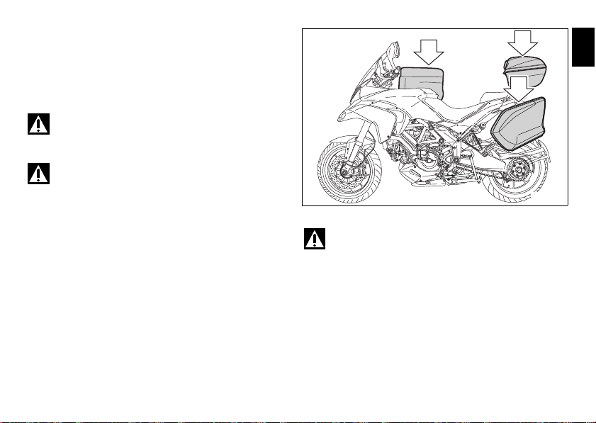
Carrying the maximum load allowed
10
Kg
10
Kg
5
Kg
fig. 1
Your motorcycle is designed for travelling over long
distances with a full load in complete safety.
Even weight distribution is critical to preserving these safety
features and avoiding trouble when performing sudden
manoeuvres or riding on bumpy roads.
Warning
The maximum speed permitted with the side panniers,
top case and the tank bag fitted must not exceed 180 km/h.
Warning
Do not exceed the total permitted weight for the
motorcycle and pay attention to information provided below
regarding load capacity.
E
Information on load capacity
The total weight of the motorcycle in running order including
rider, passenger, luggage and additional accessories should
not exceed:
430 kg.
Warning
The total weight permitted for the side panniers, top
case and the tank bag must never exceed 35 kg, divided as
follows:
10 kg max. per side pannier;
10 kg max for the top case;
5 kg max. for the tank bag.
9
Page 11

Important
E
Arrange your luggage or heavy accessories in the
lowest possible position and close to motorcycle centre.
Secure the luggage firmly to the motorcycle structure.
Luggage incorrectly secured may cause the motorcycle to
become unstable.
Never attach bulky or heavy objects to the top yoke or front
mudguard, as this would cause dangerous instability.
Do not insert objects into gaps in the frame, where they
could interfere with moving parts.
If the side panniers are fitted (available upon request from
the Ducati spare parts service), divide the baggage and
accessories based on their weight and place them uniformly
inside the side panniers. Lock both side panniers using the
suitable key lock.
Make sure the tyres are inflated to the proper pressure
indicated at page 168 and that they are in good condition.
10
Page 12
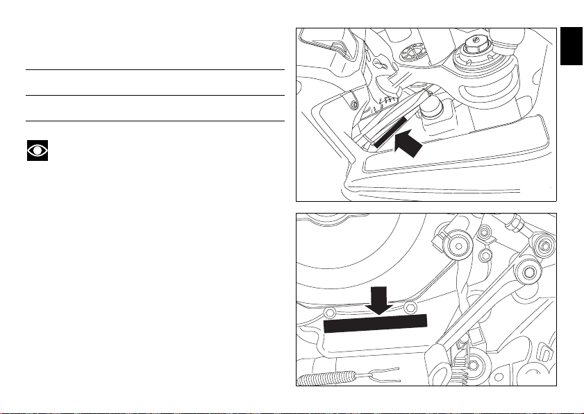
Identification data
fig. 3
fig. 2
All Ducati motorcycles have two identification numbers, for
frame (fig. 2) and engine (fig. 3).
Frame number
Engine number
Note
These numbers indicate the motorcycle model and
should be quoted when ordering spare parts.
E
11
Page 13
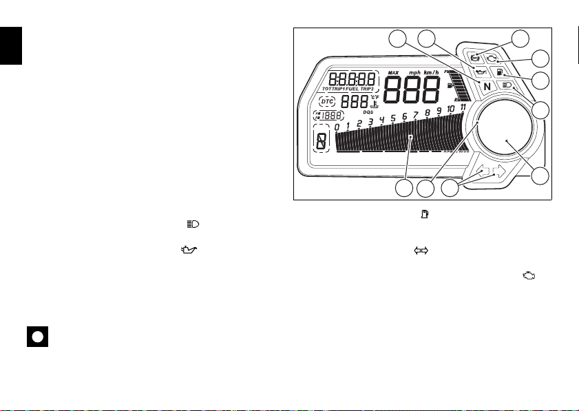
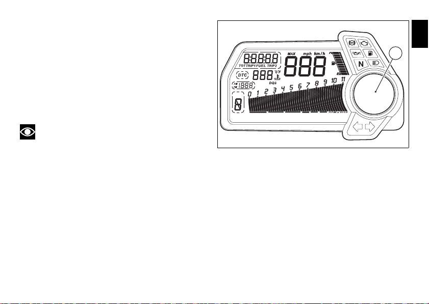
Instrument panel (Dashboard)
GEAR
DDA
LAP
2
9
1
4
6
8
1053
7
fig. 4
E
Instrument panel
1) LCD Dot-Matrix, (see page15)
2) REVOLUTION COUNTER (rpm).
Indicates engine revs per minute.
3) Neutral light N
Illuminates when the gearbox is in neutral.
4) HIGH BEAM HEADLIGHT LIGHT (BLUE).
It turns on to indicate that the high beam lights are on.
5) ENGINE OIL PRESSURE LIGHT (RED).
Illuminates when engine oil pressure is too low. It must turn
on at Key-On, but must turn off a few seconds after the
engine has started.
It may come on briefly if the engine is very hot, but should go
out again as engine speed increases.
Important
If this light (5) stays on, stop the engine or it may suffer
severe damage.
(GREEN).
6) FUEL WARNING LIGHT (AMBER).
Comes on when fuel is low and there are about 4 litres of fuel
left in the tank.
7) TURN SIGNAL LIGHTS (GREEN).
Illuminates and flashes when the turn signal is in operation.
8) “ENGINE/VEHICLE DIAGNOSIS - EOBD” LIGHT
(AMBER YELLOW).
It turns on in the case of “engine” and/or “vehicle” errors
and in some cases will lock the engine.
12
Page 14
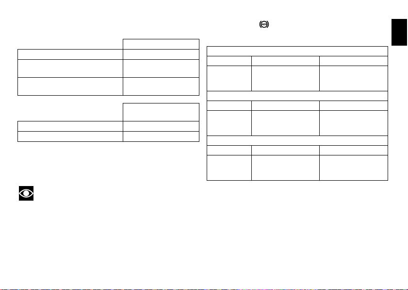
9) Limiter light “Over rev”/ traction control light “DTC”
(RED) (fig. 4):
Over rev light
No limiter Off
1st threshold - no. RPM before
the limiter threshold (*)
Rev limiter (limiter engaged due
to overrevving) (*)
No intervention Off
DTC intervention On - STEADY
(*) depending on the model, each calibration of the Engine
Control Unit may have a different ”setting” for the
thresholds that precede the rev limiter and the rev limiter
itself.
Note
If the Over rev function light and the DTC intervention
light should both come on at the same time, the instrument
panel gives priority to the Over rev function.
On - STEADY
On - Flashing
DTC intervention
lights
10) ABS LIGHTS (AMBER YELLOW) (fig. 4).
This turns on to indicate that ABS is disabled or not
functioning.
Engine off / speed below 5 Km/h
Light off Light flashing Light steady
ABS disabled with the
-
menu function “DISAB
ABS” (**)
Engine on / speed below 5 Km/h
Light off Light flashing Light steady
Light off Light flashing Light steady
ABS enabled
and
functioning
(**) The ABS should be considered actually disabled only if
the light continues to flash after starting the engine.
ABS disabled with the
-
menu function “DISAB
ABS”
Engine on / speed above 5 Km/h
ABS disabled with the
menu function “DISAB
ABS”
ABS enabled but not
functioning yet
ABS enabled but not
functioning yet
ABS disabled and not
functioning due to a
problem.
E
13
Page 15
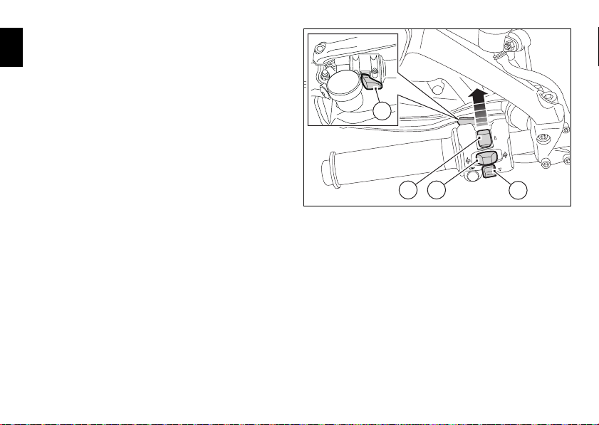
11) CONTROL BUTTON(fig. 5)
14
12
11
13
fig. 5
Button used to display and set instrument panel parameters
E
with the position ”▲”.
12) CONTROL SWITCH (fig. 5)
Button used to display and set instrument panel parameters
with the position ”▼”.
13) HIGH-BEAM FLASHER BUTTON FLASH (fig. 5)
The high-beam flash button may also be used to for LAP
functions.
14) RESET BUTTON (fig. 5).
The turn indicators off button may also be used for the
RESET/CONFIRM function on the instrument panel and for
activating the ”Riding Style”.
14
Page 16
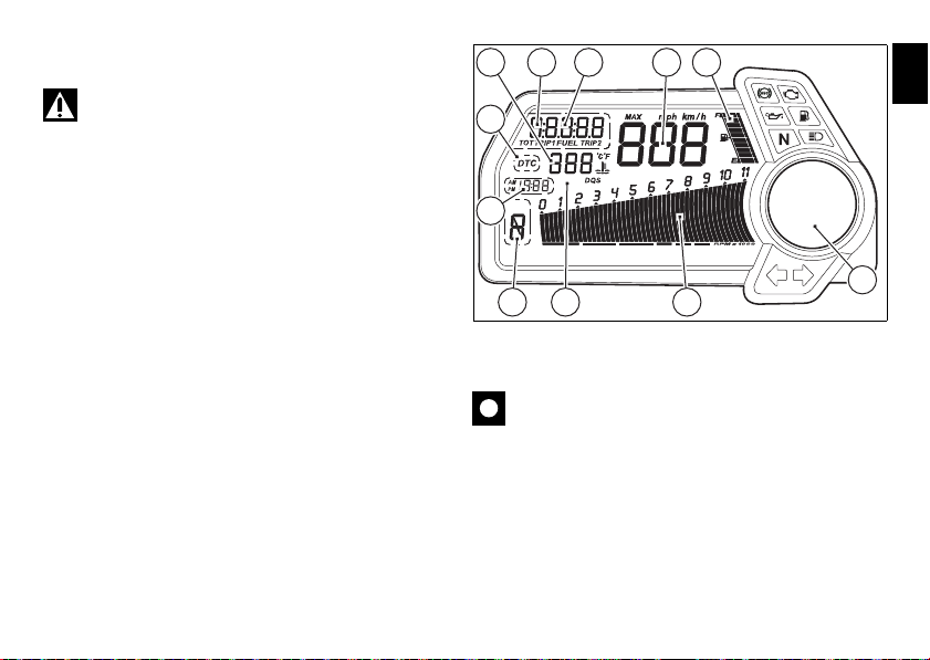
LCD unit functions
GEAR
DDA
LAP
7 6
11
513
210
8
4
9
fig. 6
Warning
Any adjustments to the instrument panel must only be
carried out when the motorcycle is stationary. Never operate
the instrument panel controls while riding the motorcycle.
1) SPEEDOMETER.
Gives road speed.
2) ODOMETER.
Shows total distance travelled.
3) TRIP METER.
Indicates distance travelled since the meters (TRIP 1 and
TRIP 2) were last reset.
4) CLOCK.
5) FUEL LEVEL
6) ENGINE RPM INDICATOR (RPM).
7) LAP TIME, MAXIMUM SPEED AND MAXIMUM RPM
RECORDING (LAP).
8) DTC INDICATOR ACTIVE/NOT ACTIVE.
9) GEAR INDICATOR.
10) WATER TEMPERATURE INDICATOR.
Indicates engine coolant temperature.
Important
Stop riding if the temperature reaches the maximum
value, otherwise the engine might be damaged.
11) LCD Dot-Matrix
E
15
Page 17
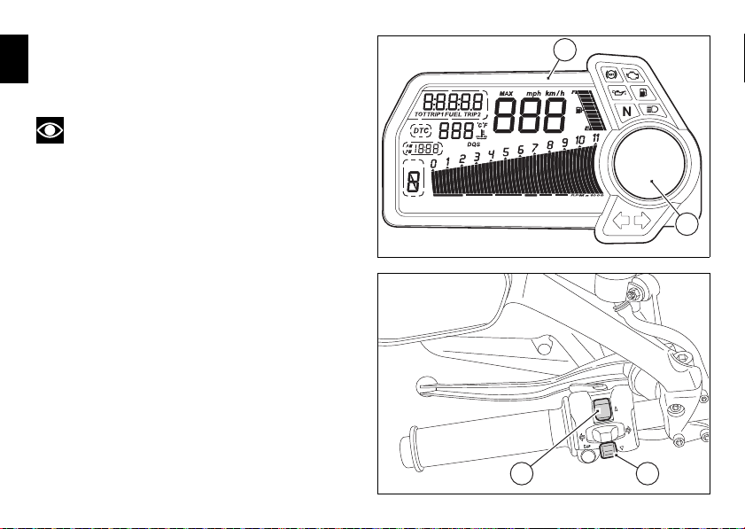
LCD - Parameter setting/display
GEAR
DDA
LAP
B
A
fig. 7
1 2
fig. 8
At the end of the check, the instrument panel always
E
displays the Odometer (TOT) as the ”main” indicator on the
main display and the “riding style” on the circular display.
Note
The check can be interrupted by pressing the button (1,
fig. 8).
At the end of the initial check, the instrument panel will
always show the ”main” display that indicates the following
information.
On the main LCD (A, fig. 7):
- Vehicle speed indication;
- Engine rpm indication (RPM);
- Gear indication;
- Clock indication;
- Fuel level indication;
- Coolant temperature indication;
- TOT - Odometer
At this point, by pressing the (1, fig. 8) “▲” switch it is
possible to switch to the following functions:
- TRIP1 - Trip meter 1
- TRIP2 - Trip meter 2
16
Page 18

LCD Dot-Matrix (B, fig. 7):
- WARNING (only if active)
- ERRORS (only if active)
- DESMO SERVICE (only if active)
- SET UP - “Riding Style” indication set
At this point, by pressing the (2, fig. 8) “▼” button it is
possible to switch to the following functions:
- RANGE - Remaining range
- CONS I. - Current fuel consumption
- CONS M. - Average fuel consumption
- AVG - Average speed
- AIR - Air temperature
- TIME TRIP - Trip time
E
17
Page 19
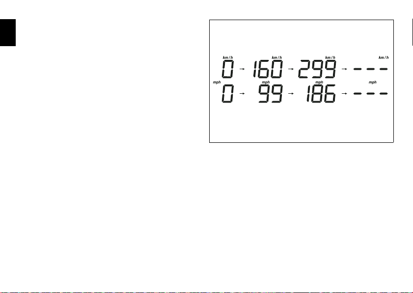
Vehicle speed indicator
fig. 9
This function displays vehicle speed (Km/h or mph
E
depending on the set measurement system).
The instrument panel receives information about the actual
speed (calculated in km/h) and displays the number
increased by 8%.
Maximum speed displayed is 299 km/h (186 mph).
Over 299 km/h (186 mph) a series of dashes will be displayed
“- - -” (not flashing).
18
Page 20
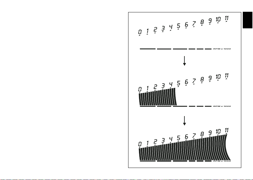
Engine rpm indicator (RPM)
fig. 10
This function displays the rpms.
The instrument panel receives the engine rpm information
and displays it.
This information is displayed progressively from the left to
the right, identifying the rpms.
E
19
Page 21
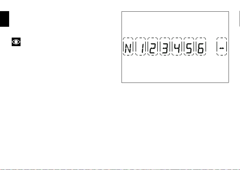
Engaged gear indicator
GEAR GEAR GEAR GEAR GEAR GEAR GEAR GEAR
fig. 11
This function displays the gears.
E
The instrument panel receives information and indicates the
engaged gear or “N” for neutral.
Note
In the case of a gear sensor “error”, a dash “-” (not
flashing) will be displayed.
20
Page 22
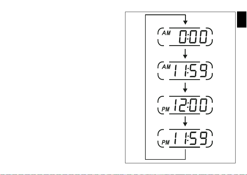
Clock
fig. 12
This function shows the time.
Time is always displayed as follows:
AM from 0:00 to 11:59
PM from 12:00 to 11:59
If battery power is suddenly cut off (Batt-OFF), when battery
power is restored and at the next Key-On, the clock is reset
and restarts from ”0:00”.
E
21
Page 23
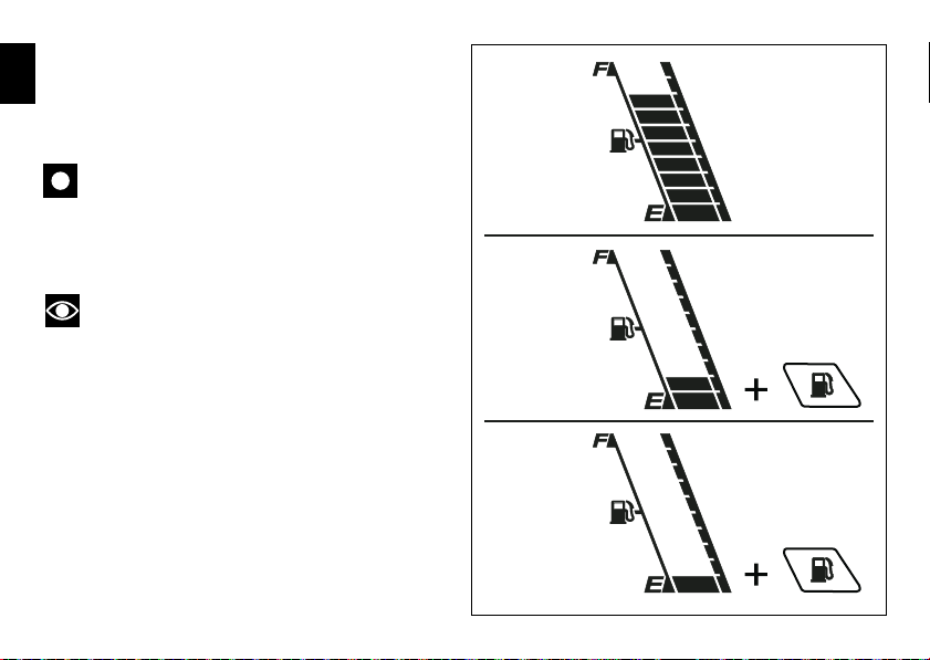
Fuel level indicator
fig. 13
Flashing mark
Steady marks
Steady marks
This function displays the fuel level.
E
The low fuel light turns on when the level goes down to 2
marks and there are still 4 litres in the tank; if the level goes
down further, the last mark will be displayed flashing.
Important
If the vehicle enters the reserve status and the light
has turned on, it is recommended to turn the vehicle off
when refuelling (Key-Off); if fuel is added without turning it
off (Key-On and engine off) the data update may not be
immediate.
Note
In the case of a level sensor “error”, the bargraph
without marks is displayed and the rest of the digit will flash.
22
Page 24
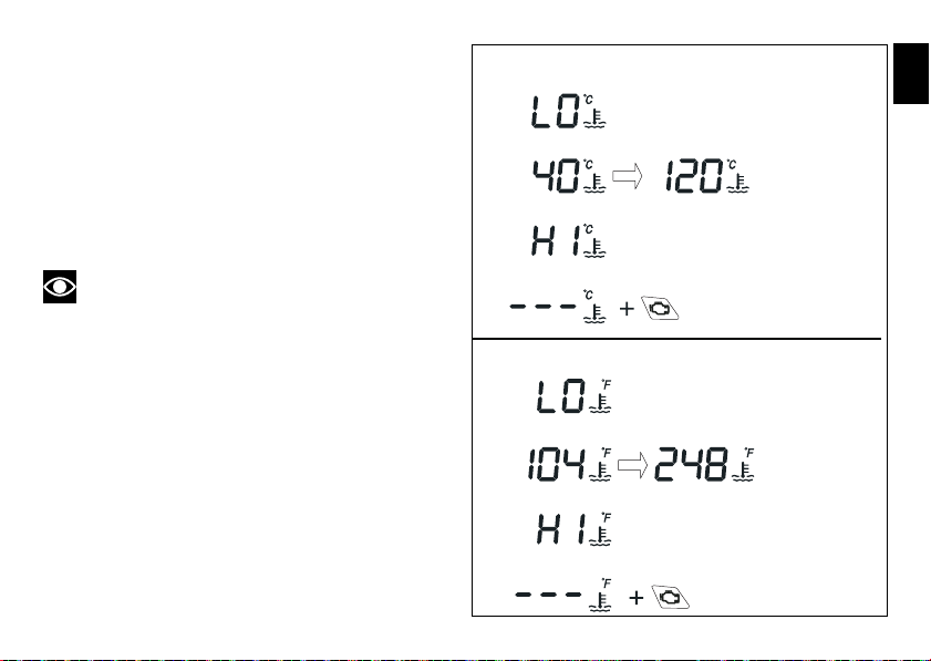
Coolant temperature
EU, CND, FRA, JAP versions
UK, USA versions
Steady reading
Steady reading Steady reading
Flashing reading
Flashing reading
Engine Diagnosis
Steady reading
Steady reading Steady reading
Flashing reading
Flashing reading
Engine Diagnosis
fig. 14
This function indicates coolant indication state.
The temperature unit of measure can be selected
(°C or °F).
The reading is indicated as follows:
- if the reading is between - 39°C and +39°C “LO” is
shown flashing on the instrument panel (steady);
- if the reading is between +40°C and +120°C it appears
on the instrument panel (steady);
- if reading is +121 °C or higher, ”HI” is shown flashing on
the information panel;
Note
In the event of a sensor ”error”, a string of flashing
dashes (”- - -”) is shown and the ”Engine/vehicle diagnosis EOBD” light (8, fig. 4) comes on.
E
23
Page 25
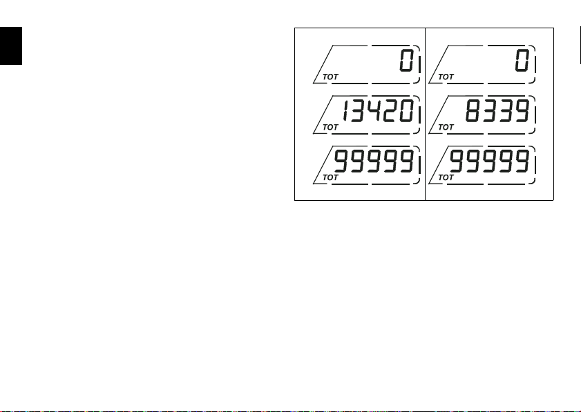
Total distance covered indicator:
fig. 15
EU, CND, FRA, JAP versions
UK, USA versions
”Odometer”
E
This function shows the total distance covered by the
vehicle.
At Key-On the system automatically enters this function.
The odometer reading is stored permanently and cannot be
reset.
If the distance travelled exceeds 99999 km (or 99999 miles),
the value “99999” will be displayed permanently.
24
Page 26
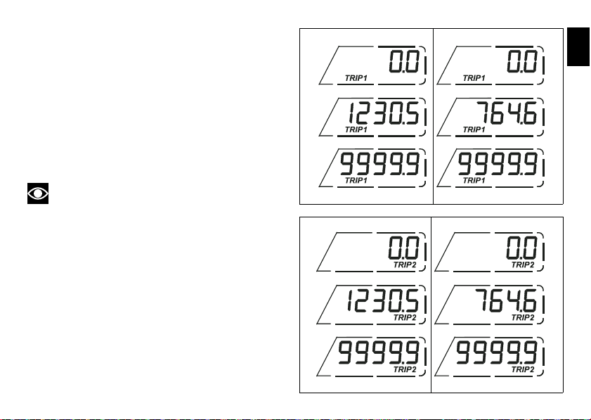
”Trip 1” meter
fig. 16
EU, CND, FRA, JAP versions
UK, USA versions
fig. 17
EU, CND, FRA, JAP versions
UK, USA versions
This function shows the distance travelled since the trip
meter was last reset.
Holding the button (1, fig. 8) ”▲” pressed for 3 seconds
when this function is displayed resets the trip meter.
When the reading exceeds 999.9, distance travelled is reset
and the meter automatically starts counting from 0 again.
If the system measurement units are changed at any
moment, or if there is an interruption in the power supply
(Battery Off), the distance travelled is reset and the count
starts from zero (considering the newly set unit of
measurement).
Note
When this value is reset, also the “Average fuel
consumption”, “Average speed” and “Trip time” functions
are reset.
”Trip 2” meter
This function shows the distance travelled since the trip
meter was last reset.
Holding the button (1, fig. 8) ”▲” pressed for 3 seconds
when this function is displayed resets the trip meter.
When the reading exceeds 999.9, distance travelled is reset
and the meter automatically starts counting from 0 again.
If the system measurement units are changed at any
moment, or if there is an interruption in the power supply
(Battery Off), the distance travelled is reset and the count
starts from zero (considering the newly set unit of
measurement).
E
25
Page 27
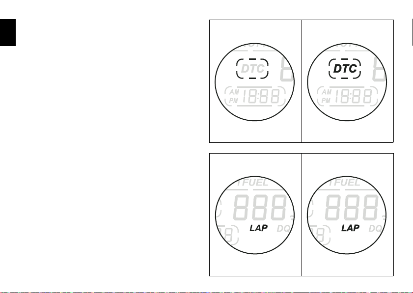
Indication if the DTC function is active/not
fig. 18
DTC OFF
DTC ON
LAP
fig. 19
LAP OFF
LAP ON
active
E
This function indicates if DTC (Ducati Traction Control) is
active.
When “DTC” is not lit up in the inside the rim, this means
that the function is disabled.
Indication if the LAP function is active/not
active
This function indicates if LAP (Lap number) is active.
When “LAP” is not lit up, this means that the function has
been switched off.
26
Page 28
Warning indication (Alarms/Signals)
GEAR
DDA
LAP
B
fig. 20
The instrument panel shows some signals/malfunctions in
real time on the circular “Dot-Matrix” display (B, fig. 20) that
are not dangerous for correct vehicle operation.
At Key-On (at the end of the check) one or more “warnings”
are displayed if they are active.
If a “warning” is activated during operation, the current
indication on the circular “Dot-Matrix” display (B, fig. 20) will
switch automatically to the indicator.
If there are multiple indicators, they will scroll automatically
every 3 seconds.
Note
No signal lights turn on if one or more “warnings” are
activated.
The following “warnings” could be displayed:
- Battery level;
- Traction control;
- Hands free key;
- Hands free key battery level;
- Coolant temperature;
- Steering release error.
When one or more “warnings” are active, it is possible to go
to other functions by pushing button (2, fig. 8) “▼”.
E
27
Page 29
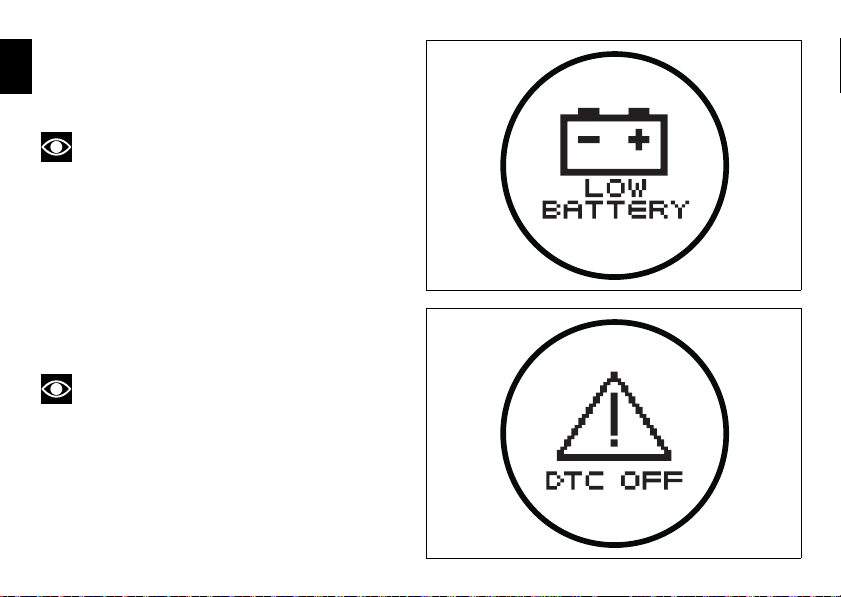
“Low” battery level
fig. 21
fig. 22
The activation of this “warning” indicates that the status of
E
the battery vehicle is low.
It is activated when the battery voltage is ≤ 11.0 Volt.
Note
In this case, Ducati recommends charging the battery
as soon as possible with the specific device, as it is possible
that the vehicle will not start.
Traction Control (DTC) deactivated
The activation of this “warning” indicates that DTC (Ducati
Traction Control) has been turned off.
Note
In this case, Ducati recommends being very careful
when riding as the vehicle behaviour will be different in
comparison to when operating with the Traction Control
activated.
28
Page 30
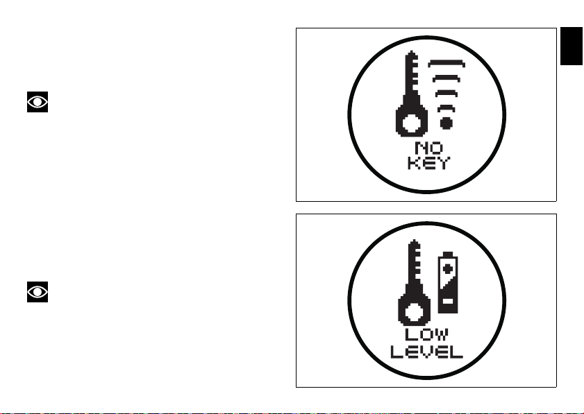
Hands Free key (HF) not recognised
fig. 23
fig. 24
The activation of this “warning” indicates that the Hands
Free system does not detect the active key (1, fig. 60) near
the vehicle.
Note
In this case, Ducati recommends checking that the
active key (1, fig. 60) is near the vehicle (and has not been
lost) and that it functions properly.
”Low” Hands Free key (HF) battery level
The activation of this “warning” indicates that the Hands
Free system has detected that the battery that permits the
active key (1, fig. 60) to communicate and turn the vehicle on
is almost discharged.
Note
In this case, Ducati recommends replacing the battery
as soon as possible as described in the paragraph “Replacing
the active key battery” (page 88).
E
29
Page 31

”High” engine coolant temperature
fig. 25
fig. 26
The activation of this “warning” indicates that the engine
E
coolant temperature is high.
It is activated when the temperature reaches 121°C (250°F).
Note
In this case, Ducati recommends stopping and shutting
off the engine immediately; make sure that the fans are
working.
Steering release error - Steering still
locked
The activation of this “warning” indicates that the Hands
Free System was not able to extract the steering lock.
Warning
In this case, Ducati recommends turning the vehicle
off and on (Key-Off / Key-On) holding the handlebar pressed
down to the end stop. If the signal remains (and the steering
does not “release”) contact a Ducati Dealer or Authorised
Service Centre.
30
Page 32

Instrument panel diagnosis
This function identifies any abnormal vehicle behaviours.
The instrument panel activates any abnormal vehicle
behaviours in real time (ERRORS).
At Key-On (at the end of the check) one or more “ERRORS”
are displayed (only if they are active).
If an “error” is activated during operation, the current
indication on the circular “Dot-Matrix” display (B, fig. 7) will
switch automatically to the indicator.
If there are multiple errors, they will scroll automatically
every 3 seconds; the “Engine/vehicle diagnosis - EOBD”
light (8, fig. 4) always turns on when one or more errors are
activated.
WARNING LIGHT ERROR MESSAGE ERROR
BBS/DTC Black Box / Traction Control control unit
GEAR SENSOR Gear sensor
FUEL SENSOR Fuel Level Sensor
SPEED SENSOR Speed sensor
EXVL ERROR Exhaust valve starter motor
UNKNOW DEVICE Unknown control unit
When one or more errors are active, it is possible to go to
other functions by pushing the button (2, fig. 8) “▼”.
The table below shows the errors that can be displayed.
a Ducati Dealer or Authorised Service Centre.
Warning
When one or more errors are displayed, always contact
E
31
Page 33

WARNING LIGHT ERROR MESSAGE ERROR
E
DEVICE ECU ECU control unit not functioning
DEVICE DASHBOARD Instrument panel not functioning
DEVICE HANDS FREE Hands Free control unit not functioning
DEVICE BBS - DTC Black Box control unit not functioning
THROTTLE POSITION Incorrect throttle position
ACCELER. POSITION Incorrect accelerator position
ETV MOTOR Throttle starter motor not functioning
ETV RELAY Relay starter motor not functioning
PRESSURE Atmospheric pressure sensor
ENGINE TEMPERAT. Engine temperature
AIR TEMP. Air temperature
FUEL INJECTION Injection relay
32
Page 34

WARNING LIGHT ERROR MESSAGE ERROR
COIL Coil
INJECTOR Injector
PICK-UP Timing/rpm sensor
LAMBDA Lambda sensor
LAMBDA HEATER Lambda heater
FAN RELAY Fan relay
HIGH BEAM High beam headlight relay
LOW BEAM Low beam headlight relay
CAN CAN communication line
BATTERY Battery voltage (HIGH or LOW)
DEVICE DES Suspension ECU not functioning
DES GENERIC Problem related to suspension ECU operation
E
33
Page 35

WARNING LIGHT ERROR MESSAGE ERROR
E
STOP LIGHT Rear stop light
ECU GENERIC ECU error
KEY ERROR HF communication problem
HANDS FREE GENERIC Hands Free ECU error
34
DES FRONT COMPRESS. Problem with the stepper that adjusts suspension front
compression
DES FRONT REBOUND Problem with the stepper that adjusts front suspension
rebound
DES REAR COMPRESS. Problem with the stepper that adjusts suspension rear
compression
DES REAR REBOUND Problem with the stepper that adjusts suspension rear
rebound
DES PRELOADER ADJUSTER Problem with the DC starter motor that adjusts the rear
suspension preload.
Page 36

Maintenance indicator
This function indicates that the vehicle is about to or has
travelled a distance for which an Authorised Ducati Service
Centre should be contacted to have the general maintenance
or oil change performed.
Residual range indication when the
SERVICE is due
When 1000 Km (621 miles) are left until reaching the mileage
programmed by Ducati for having the ”SERVICE”
performed, the instrument panel activates (at the end of the
initial check) the indication of which type of service should be
performed and the residual range (count-down).
The indication is activated each time the motorcycle is turned
on (Key-On) for 5 seconds (flashing).
The residual range is updated every 100 Km (-1000, -900,
-800, -700, etc…..).
Warning
This message can only be reset by the Ducati Dealer or
Authorised Service Centre that performs the maintenance.
Indication of range reached for SERVICE
If you reach the mileage programmed by Ducati, the
information panel will activate (at the end of the initial check)
the indication that you should go to a Ducati Dealer or
Authorised Service Centre to have the scheduled
maintenance “DESMO SERVICE” or “OIL SERVICE”
performed.
The indication is activated each time the motorcycle is turned
on (Key-On) (not flashing); pressing the button (2, fig. 8) “▼”
the other functions can be displayed;
The indication will remain until it is reset and it can be
displayed at any moment by scrolling the functions.
Warning
This message can only be reset by the Ducati Dealer or
Authorised Service Centre that performs the maintenance.
Note
The distance travelled thresholds are defined in an
“absolute” sense and do not account for when the “reset”
request for the indication is made by the Authorised Ducati
Service Centre.
E
35
Page 37

Maintenance table
E
Indicator Mileage travelled count down -1000
1 1000
2
3
4
5
6
7
8
9
36
11000
12000 •
23000
24000 •
35000
36000 •
47000
48000 •
59000
60000 •
71000
72000 •
83000
84000 •
95000
96000 •
DESMO SERVICE
•
•
•
•
count down -1000
OIL SERVICE
•
•
•
•
DESMO
SERVICE
OIL SERVICE
•
Page 38

E
fig. 27
37
Page 39

SET UP - “Riding Style set” indication
fig. 28
“Base” version
fig. 29
Single passenger
Single passenger with luggage
Two passengers
Two passengers with luggage
“S” version
This function indicates the ”Riding Style” set for the vehicle.
E
Four “Riding Styles” are available: SPORT, TOURING,
URBAN and ENDURO.
Each riding style can be changed using the “Riding Style”
function.
In the “base” version, only the set riding style is indicated.
In the “S” version, the setup (fig. 29) and the riding style
(fig. 30) that are set are indicated.
38
Page 40

“S” version
fig. 30
E
39
Page 41

“RANGE” indicator - remaining range
fig.31
EU, CND, FRA, JAP versions
UK, USA versions
This function indicates the distance that can be travelled with
E
the fuel currently in the tank.
The calculation is made based on the fuel level and an
average consumption in reference to the last 90 seconds of
driving (not the average fuel consumption “CONS M.”).
If you refuel adding more than 4 litres of fuel with the vehicle
switched off (Key-Off), at the subsequent Key-On, the
remaining range reading will be updated instantaneously and
will be calculated based on the new fuel level and an average
fuel consumption of 18.0 Km/l; otherwise (that is, if you add
less than 4 litres) the reading will only be updated after the
vehicle is in movement (not instantaneously).
When the range arrives to “0” the indication will flash
together with the symbol (motorcycle + fuel pump).
The active calculation phase occurs when the engine is
running and the vehicle is moving (moments when the
vehicle is not moving when speed is equal to 0 and/or when
the engine is off are not considered).
Warning
It is recommended to turn off the motorcycle (Key-Off)
when refuelling; if adding fuel without turning off the
motorcycle (Key-On/engine off), the reading will be updated
as soon as the vehicle starts to move (speed greater than
zero).
Warning
The residual range that is measured is an approximate
value; Ducati recommends not trying to use all the residual
range indicated.
40
Page 42

Indicator ”CONS I.” - Instantaneous fuel
fig. 32
EU, CND, FRA, JAP versions
UK, USA versions
fig. 33
EU, CND, FRA, JAP versions
UK, USA versions
consumption
This function indicates the “instantaneous” fuel
consumption.
The calculation is made considering the quantity of fuel used
and the distance travelled during the last second. the datum
is expressed in “l / 100” ( litres / 100 Km ); it is possible to
set the unit of measurement ”Km / l” ( kilometres / litre )
through the ”Setting special” function.
The active calculation phase only occurs when the engine is
running and the vehicle is moving (moments when the
vehicle is not moving when speed is equal to 0 and/or when
the engine is off are not considered). Dashes “- -.-”. are
shown on the display when the calculation is not made.
Indicator ”CONS M.” - Average fuel
consumption
This function indicates the “average” fuel consumption.
The calculation is made considering the quantity of fuel used
and the km travelled since the last Trip 1 reset. When Trip 1
is reset, the value is set to zero and the first available value
is shown on the display 10 seconds after the reset. Dashes
“- -.-” are shown on the display during the first 10 seconds
when the value is not yet available.
the datum is expressed in “l / 100” ( litres / 100 Km ); it is
possible to set the unit of measurement ”Km / l” ( kilometres
/ litre ) through the ”Setting special” function.
The active calculation phase occurs when the engine is
running and the vehicle is stopped (moments when the
vehicle is not moving and the engine is off are not
considered).
E
41
Page 43

Indicator “AVG” - Average speed
fig. 34
EU, CND, FRA, JAP versions
UK, USA versions
fig. 35
EU, CND, FRA, JAP versions
UK, USA versions
This function shows the average speed of the motorcycle.
E
The calculation is made considering the distance and time
travelled since the last Trip 1 reset. When Trip 1 is reset, the
value is set to zero and the first available value is shown on
the display 10 seconds after the reset. Dashes “- -.-” are
shown on the display during the first 10 seconds when the
value is not yet available.
The active calculation phase occurs when the engine is
running and the vehicle is stopped (moments when the
vehicle is not moving and the engine is off are not
considered).
The calculated value is displayed increased by 8% to align it
with the vehicle indicated speed.
Air temperature indicator
This function shows the external temperature.
Display limits: -39°C ÷ +124°C
In the event of a sensor FAULT (-40°C,+125°C or
disconnected), a string of dashes “- - -” (not flashing) is
displayed and the “Engine/Vehicle Diagnosis - EOBD” light
(8, fig. 4) comes on and an error is indicated inside “Errors”
Menu.
Note
When the vehicle is stopped, the engine heat could
influence the displayed temperature.
42
Page 44

When the detected temperature drops to 4°C (39°F), the
fig. 36
fig. 37
display warns that the formation of ice is possible. The
indication turns off when the temperature rises to 6°C (43°F).
Warning
This warning does not exclude the possibility of icy
road sections even at temperatures above 4°C (39°F); when
external temperatures are ”low” it is always recommended
to drive carefully, particularly on sections that are not
exposed to the sun and/or on bridges.
Indicator ”TIME TRIP” - Trip time
This function shows the vehicle trip time.
The calculation is made considering the time travelled since
the last Trip 1 reset. When Trip 1 is reset, the value is set to
zero.
The active phase calculation occurs when the engine is
running and the vehicle is stopped (when the vehicle is not
moving and the engine is off the time is automatically
stopped and restarts when the counting active phase starts
again).
E
43
Page 45

“Riding Style” function (riding style
change)
E
This function changes the motorcycle riding style.
Each riding style is associated with a different intervention
level of the traction control (DTC - Ducati Traction Control)
and different engine power and output.
For the “S” version with electronic suspension, each riding
style change is also associated with different motorcycle
setup.
To change the motorcycle riding style, press the reset button
once (14, fig. 5) and the ”SET UP” menu will appear on the
circular display (B, fig. 7).
The desired riding style can be selected by pressing the
same reset button multiple times (14, fig. 5). Press the same
button for 3 seconds to confirm the riding style.
If the twistgrip is closed (vehicle stopped) the riding style
change will occur immediately; if the twistgrip grip is open
(vehicle moving) the message “CLOSE THROTTLE TO
ACTIVATE” will appear on the display, which means that the
throttle must be closed; this message will appear for 5
seconds, during which the gas must be closed in order to
activate the new riding style.
If the twistgrip is not closed after 5 seconds, the procedure
is aborted (no change is made).
If the “SET UP” menu is activated and the rest button is not
pressed (14, fig. 5) for 10 consecutive seconds, the
instrument panel will automatically exit the display mode
without making any change.
44
Warning
Ducati recommends changing the riding style when
the vehicle is stopped. If the riding style is changed while
riding, be very careful (it is recommended to change the
riding style at a low speed).
Page 46

Press RESET for
2 s.
fig. 38
Press RESET
Press
RESET
Press RESET
Press RESET
Press RESET for
2 s.
Press RESET for
2 s.
Press RESET for
2 s.
Press RESET“Base” and “S” version
E
45
Page 47

“LOAD” FUNCTION (setup change)
This function, which is only available in the “S” version,
E
changes the vehicle setup.
Each individual riding style is associated with four different
setups (fig. 29).
To change the vehicle setup, press the reset button (14, fig.
5) for 3 seconds consecutively and the ”LOAD” menu will
appear on the circular display (B, fig. 7).
The desired setup can be selected by pressing the same
reset button multiple times (14, fig. 5). To confirm the setup,
press the same reset button again for 3 seconds (14, fig. 5).
At the end of the 3 seconds, the change occurs immediately
and the instrument panel exits the display mode
automatically.
Example: if a setup change is made from ”individual
passenger” to ”passenger with luggage”, the change may
vary depending on the set riding style (the “passenger with
luggage” setup may have different adjustments depending
on if the riding style that is set to SPORT, TOURING, URBAN
or ENDURO).
If the “LOAD” menu is activated and the rest button is not
pressed (14, fig. 5) for 10 consecutive seconds, the
instrument panel will automatically exit the display mode
without making any change.
46
Warning
The setup change can lead to a different motorcycle
riding style; it is recommended to be careful if changing the
setup while riding (it is recommended to change the setup at
a low speed).
Page 48

E
press RESET for 2 sec.
fig. 39
Press
RESET
single passenger setup
activation
single passenger with
luggage setup activation
two passenger setup
activation
two passenger with luggage
setup activation
Press RESET
Press RESET
Press RESET
Press RESET for
2 sec.
Press RESET for
2 sec.
Press RESET for
2 sec.
Press RESET for
2 sec.
Version “S” only
47
Page 49

“Setting” menu
This menu is used to set/enable some motorcycle functions.
E
To access the “setting menu” press the button (2, fig. 8)
“▼” for 2 seconds.
Note
Once this menu has been accessed, it is not possible
to scroll the functions on the main display (A, fig. 7).
Important
For safety reasons, the setting menu can only be
accessed when motorcycle speed is lower than or equal to
20 Km/h. If this menu is open and the speed of the
motorcycle exceeds 20 km/h, the instrument panel
automatically exits the menu and returns to the ”main”
display.
48
The setting menu contains the following ”items”:
- EXIT
-ABS
- BATTERY
- SETUP
- B.LIGHT
-LAP
-DTC
-RPM
-CLOCK
-PIN CODE
- EXIT
To exit the setting menu, use button (1, fig. 8) “▲” or button
(2, fig. 8) “▼” to select “EXIT” (present at the beginning and
the end of the menu item list) and press the reset button (14,
fig. 5).
Page 50

Press “▲”
fig. 40
Press “▼”
Press “▲”
Press “▲”
Press “▼”
Press “▼”
Press “▼”
Press “▼”
Press “▼”
Press “▼”
Press “▼”
Press “▼”
Press “▼” for 2 sec.
Press “▼”
E
49
Page 51

ABS disabling function
fig. 41
This function disables the ABS control unit.
E
To display the function, enter the “Setting” menu page 48
and access the “ABS” page.
After accessing the display, press the reset button (14, fig. 5)
for 3 seconds to disable ABS.
The instrument panel will send the disabling request
(”WAIT....” will appear on the circular display (B, fig. 7) for 6
seconds) and then if ABS is actually disabled, ”DISABLED”
will appear on the circular display (B, fig. 7).
The ABS light (10, fig. 4) signals the disabling, switching from
an ”off” status to ”flashing”.
To re-enable the ABS system, turn the motorcycle off and on
(Key-Off/Key-On).
Note
If the disabling request was not successful, the
instrument panel will display ”NOT DISABLED” in the
circular display (B, fig. 7).
In this case, repeat the procedure. If the problem persists,
contact your Ducati dealer or Authorised Service Centre.
50
Page 52

fig. 42
Press RESET
Press RESET
for 3 sec.
Press “▲”
Press
RESET
Press “▼”
Press RESET
E
51
Page 53

Battery voltage indicator (BATTERY)
E
This function describes the battery voltage indicator.
To display the function, enter the “Setting” menu page 48
and access the “BATTERY” page.
The information will be displayed as follows:
- if battery voltage is between 11.8 and 14.9 Volt the
reading will be displayed steady;
- if battery voltage is between 11.0 and 11.7 Volt the
reading will be displayed flashing;
- if battery voltage is between 15.0 and 16.0 Volt the
reading will be displayed flashing;
- if battery voltage is equal to or less than 10.9 Volt,
”LOW” is shown flashing and the “Vehicle/Engine
Diagnosis - EOBD” light (8, fig. 4) comes on;
- if battery voltage is equal to or greater than 16.1 Volt,
”HIGH” is shown flashing and the “ Vehicle/Engine
Diagnosis - EOBD” light (8, fig. 4) comes on;
Note
Dashes “- - -“ appear if the reading is not available.
52
Page 54

fig. 43
Press RESET
Press RESET Press RESET Press RESET
E
53
Page 55

“Riding Mode” customisation
This function customises each riding style.
E
To display the function, enter the “Setting” menu page 48
and access the “SET UP” page.
When accessing the function, the four riding styles appear on
the circular display (B, fig. 7); to customise the parameters,
use buttons (1, fig. 8) “▲” and (2, fig. 8) “▼” to select the
riding style to be changed and press the reset button (14, fig.
5) to confirm.
The parameters that can be ”customised” are “DTC” (Ducati
Traction Control), ”ENGINE” and, only for “S” versions, the
electronic suspension regulations “DES”.
Any parameter change made is saved in the memory also
after a Battery-Off.
To change the DTC parameters see the “DTC (Ducati
Traction Control)” paragraph page 56.
To change the Engine parameters see the “ENGINE (engine
power control)” paragraph page 60.
To change the electronic suspension parameters (only for
“S” versions) see the “DES (Ducati Electronic Suspension)”
paragraph.
The parameters set by Ducati for each individual driving style
can be reset with the ”DEFAULT” function.
To reset the “default” parameters see the “DEFAULT
(Resetting Ducati default parameters)” paragraph page 70.
54
Warning
Changes should only be made to the parameters by
people who are experts in motorcycle setup; if the
parameters are changed accidentally, use the “DEFAULT”
function to reset the parameters.
Page 56

E
fig. 44
Press RESET
Press “▼”
Press “▲”
Press RESET
Press RESET
Press RESET
Press RESET
Press “▲”
Press “▲”
Press “▼”
Press “▼”
Press “▼”
Press “▼”
“base”
“S”
Press “▲”
55
Page 57

DTC (Ducati Traction Control) setting
function
E
This function customises the intervention level of the DTC
(Ducati Traction Control).
To display the function, enter the “Setting” menu page 48
and access the “SET UP” page. Use buttons (1, fig. 8) “▲”
and (2, fig. 8) “▼” to select the riding style to be changed and
press the reset button (14, fig. 5) to access the ”DTC”
function.
When accessing the function, the set DTC level ”LEVEL N”
will appear at the top of the circular display (B, fig. 7).
The intervention levels range from “1” to “8”; the higher the
number, the greater the intervention of the Traction Control
system.
To change the DTC intervention level, use buttons (1, fig. 8)
“▲” and (2, fig. 8) “▼” to select the ”NEW LEVEL”
indication and press the reset button (14, fig. 5).
The number to be set is shown on the display; buttons
(1, fig. 8) “▲” and (2, fig. 8) “▼” can increase or decrease
the number; press the reset button (14, fig. 5) to confirm the
new level.
At this point, store the new setting by pressing the reset
button (14, fig. 5) with “MEMORY” displayed.
The upper indication “LEVEL N.2” will be updated to confirm
that the new setting was “received” and stored.
To exit the function, select “EXIT” and press the reset button
(14, fig. 5).
The DTC intervention increases, passing from level 1 to level
8.
The following table indicates the most suitable level of DTC
intervention for the various riding types as well as the default
56
settings in the ”Riding Modes” that can be selected by the
rider:
DTC
RIDING TYPE USE DEFAULT?
LEVEL
1 ENDURO
Professional
2 ENDURO Off-road for less experienced
3 TRACK Track for very expert riders.
4 SPORT Sporty driving on a road or
5 TOURING Normal riding It is the
6 URBAN “Very safe” riding together
7RAIN Wet road NO
8 HEAVY RAIN Wet road and slippery asphalt NO
Off-road for very expert
riders. It permits elevated
rear wheel spin. It does not
intervene in time on asphalt.
riders. Does not intervene in
time on asphalt.
Permits sliding sideways
track
with the use of an 100HP
ENGINE (maximum power
100 HP)
NO
It is the
default level
for the
“ENDURO”
Riding Style
NO
It is the
default level
for the
“SPORT”
Riding Style
default level
for the
“TOURING”
Riding Style
It is the
default level
for the
“URBAN”
Riding Style
Page 58

fig. 45
Press RESET
Press “▼” for
4 sec.
Press RESET
Press RESET
Press “▲” for
4 sec.
Press “▲”
Press RESET
Press “▼”
Press RESET for
3 sec.
“Base” version
“S” version
E
57
Page 59

Tips on how to select the sensitivity level
E
Warning
The 8 level settings of the DTC were calibrated using
tyres of the same make, model and size as those originally
fitted to the motorcycle.
The use of tyres of different size to the original tyres may
alter the operating characteristics of the system.
In the case of minor differences, such as for example, tyres
of a different make and/or model than the original, but with
the same dimensions (rear = 190/55-17; front = 120/70-17),
it may be sufficient to simply select the most suitable level
setting from those available to restore optimal system
operation.
If tyres of a different size class are used or if the tyre
dimensions differ significantly from the original tyres, it may
be that the system operation is affected to the point where
none of the 8 available level settings will give satisfactory
results.
In this case is it is advisable to deactivate the traction control
system.
If level 8 is selected, the DTC control unit will kick in at the
slightest hint that the rear wheel is starting to spin.
Between level 8 and level 1 there are a further 6 intermediate
levels. The level of DTC intervention decreases in equal
steps from level 8 to level 1.
When levels 1, 2 or 3 is selected the DTC control unit will
allow the rear wheel to spin and also slide sideways on
exiting a corner; we recommend that this setting is only used
by very experienced riders.
58
The choice of the correct level depends on 3 main variables:
1) The grip (type of tyre, amount of tyre wear, the road/
track surface, weather conditions, etc.)
2) The characteristics of the path/circuit (bends all taken at
similar speeds or at very different speeds)
3) The riding style (whether the rider has a “smooth” or a
“rough” style)
The relation of the DTC intervention level to grip conditions:
The choice of level setting depends greatly on the grip
conditions of the track/circuit (see below, tips for use on the
track and on the road).
The relation of the DTC intervention level to the circuit
characteristics:
If all the corners on the track/circuit can be taken at a similar
speed, it will be easier to find an intervention level that is
satisfactory for every bend; on the other hand, if the track
has, for example, one corner that is much slower than all the
others, it will necessary to find a compromise level (on the
slow corner the DTC will tend to control more than on the
faster corners).
The relation of the DTC intervention level to riding style:
The DTC will tend to kick in more with a “smooth” riding
style, where the bike is leaned over further, rather than with
a “rough” style, where the bike is straightened up as quickly
as possible when exiting a turn.
Page 60

Tips for use on the track
We recommend level 8 be used for a couple of full laps (to
allow the tyres to warm up) in order to get used to the
system. Then try levels 7, 6, etc., in succession until you
identify the DTC intervention level that suits you best (always
try each level for at least two laps to allow the tyres to warm
up).
Once you have found a satisfactory setting for all the corners
except one or two slow ones, where the system tends to
kick in and control too much, you can try to modify your riding
style slightly to a more “rough” approach to cornering i.e.
straighten up more rapidly on exiting the corner, instead of
immediately trying a different level setting.
Tips for use on the road
Activate the DTC, select level 8 and ride the motorcycle in
your usual style; if the level of DTC intervention seems
excessive, try reducing the setting to levels 7, 6, etc., until
you find the level that suits you best.
If changes in the grip conditions and/or circuit characteristics
and/or your riding style, and the level setting is no longer
suitable, switch to the next level up or down and proceed as
described above to determine the best setting (e.g. if with
level 7 the DTC intervention seems excessive, switch to
level 6; alternatively, if on level 7 you cannot perceive any
DTC intervention, switch to level 8).
E
59
Page 61

ENGINE setting function (Engine Power
Control)
E
This function customises engine power and output.
To display the function, enter the “Setting” menu page 48
and access the “SET UP” page. Use buttons (1, fig. 8) “▲”
and (2, fig. 8) “▼” to select the riding style to be changed and
press the reset button (14, fig. 5) to access the ”ENGINE”
function.
When accessing the function, the engine setting (150 HIGH,
150 LOW or 100 HP) appears at the top of the circular display
(B, fig. 7).
Note
In Japan and France versions, the circular display
(B, fig. 7) displays the settings (HIGH, MID and LOW).
To change the engine ”power”, use buttons (1, fig. 8) “▲”
and (2, fig. 8) “▼” to select the ”NEW SET” indication and
press the reset button (14, fig. 5).
Use buttons (1, fig. 8) “▲” and (2, fig. 8) “▼” to select one
of the three options (150 HIGH, 150 LOW or 100 HP) or
(HIGH, MID e LOW) for France and Japan versions; press the
reset button (14, fig. 5) to confirm the new level.
At this point, store the new setting by pressing the reset
button (14, fig. 5) for 3 seconds with “MEMORY” displayed.
The upper indication will be updated to confirm that the new
setting was “received” and stored.
To exit the function, select “EXIT” and press the reset button
(14, fig. 5).
60
Page 62

E
fig. 46
Press RESET
“▼”
Press RESET for
3 sec.
Press RESET
“▼”“▲”“▲”
Press RESET
Press RESET
“▼”
“▼”“▲”“▲”“▼”
vs. FRA, JAP
61
Page 63

DES setting function (Ducati Electronic
Press RESET
Press RESET
Press “▼”
Press “▲”
fig. 47
Press “▲”
Press “▲”
Press “▲”
Press “▼”
Press “▼”
Press “▼”
Suspension)
E
Available in the “S” version only.
To display the function, enter the “Setting” menu page 48
and access the “SET UP” page. Use buttons (1, fig. 8) “▲”
and (2, fig. 8) “▼” to select the riding style to be changed and
press the reset button (14, fig. 5) to access the ”DES”
function.
When accessing the function, the four different types of
setup appear on the circular display (B, fig. 7) (fig. 29).
Use buttons (1, fig. 8) “▲” and (2, fig. 8) “▼” to select the
setup to customise and press the reset button (14, fig. 5).
62
Page 64

The three parameters to change appear on the circular
fig. 48
Press RESET
Press RESET
Press “▼”
Press “▲”
Press “▼”
Press “▼”
Press “▲”
Press “▲”
display (B, fig. 7):
- FRONT: adjustment of the front shock absorber rebound
and compression;
- REAR: adjustment of the rear shock absorber rebound
and compression;
- PRE-LOAD: adjustment of the rear shock absorber spring
preload.
Use buttons (1, fig. 8) “▲” and (2, fig. 8) “▼” to select the
parameter to change and press the reset button (14, fig. 5).
E
63
Page 65

“FRONT” adjustment
- the top of the circular display (B, fig. 7) will show the set
E
compression [C.] and rebound [R.].
- Use buttons (1, fig. 8) “▲” and (2, fig. 8) “▼” to select
the parameter to change and press the reset button
(14, fig. 5).
- the number to change appears on the circular display
(B, fig. 7);
- buttons (1, fig. 8) “▲” and (2, fig. 8) “▼” can increase or
decrease the number (between 1 and 32);
- press the reset button (14, fig. 5) to confirm the new
level.
Note
Increasing the set value “decreases” the hydraulic
“braking”; decreasing the value ”increases” the hydraulic
”braking” of the shock absorber.
At this point, store the new setting by pressing the reset
button (14, fig. 5) for 3 seconds with “MEMORY” displayed.
The upper indication [C.] or [R.] will be updated to confirm
that the new setting was “received” and stored.
To exit the function, select “EXIT” and press the reset button
(14, fig. 5).
64
Page 66

fig. 49
RESET
Press RESET
RESET
Press
“▲”
Press “▼” for 6 s
RESET for 3 s
RESET for 3 s
RESET RESET
RESET
“S” version
Press
“▲”
Press
“▼”
Press
“▼”
Press
“▲”
Press
“▼”
Press “▼” for 12 s
Press “▲” for 6 s
Press “▲” for 12 s
Press “▼”
Press “▲”
Press “▼”
Press “▲”
Press RESET
E
65
Page 67

“REAR” adjustment
- the top of the circular display (B, fig. 7) will show the set
E
compression [C.] and rebound [R.];
- use buttons (1, fig. 8) “▲” and (2, fig. 8) “▼” to select
the parameter to change and press the reset button (14,
fig. 5);
- the number to be changed is shown on the display;
- buttons (1, fig. 8) “▲” and (2, fig. 8) “▼” can increase or
decrease the number (between 1 and 32);
- press the reset button (14, fig. 5) to confirm the new
level.
Note
Increasing the set value “decreases” the hydraulic
“braking”; decreasing the value ”increases” the hydraulic
”braking” of the shock absorber.
At this point, store the new setting by pressing the reset
button (14, fig. 5) for 3 seconds with “MEMORY” displayed.
The upper indication [C.] or [R.] will be updated to confirm
that the new setting was “received” and stored.
To exit the function, select “EXIT” and press the reset button
(14, fig. 5).
66
Page 68

fig. 50
RESET
Press RESET
RESET
Press
“▲”
Press “▼” for 6 s
RESET for 3 s
RESET for 3 s
RESET
RESET
RESET
“S” version
Press
“▲”
Press
“▼”
Press
“▼”
Press
“▲”
Press
“▼”
Press “▼” for 12 s
Press “▲” for 6 s
Press “▲” for 12 s
Press “▼”
Press “▲”
Press “▼”
Press “▲”
Press RESET
E
67
Page 69

“PRE-LOAD” adjustment
- the top of the circular display (B, fig. 7) will show the
E
“preload” and a bargraph indicating the set value;
- use buttons (1, fig. 8) “▲” and (2, fig. 8) “▼” to select
“NEW SET” and press the reset button (14, fig. 5);
- the number to be changed is shown on the display;
- buttons (1, fig. 8) “▲” and (2, fig. 8) “▼” can increase or
decrease the number (between 1 and 16);
- press the reset button (14, fig. 5) to confirm the new
level.
Note
Increasing the set value “stiffens” the rear shock
absorber; decreasing the value ”softens” the rear shock
absorber.
At this point, store the new setting by pressing the reset
button (14, fig. 5) for 3 seconds with “MEMORY” displayed.
The upper indication and the bargraph will be updated to
confirm that the new setting was “received” and stored.
To exit the function, select “EXIT” and press the reset button
(14, fig. 5).
68
Page 70

fig. 51
RESET
Press “▲” for 4 s
Press “▼” for 4 s
RESET for 3 s
Press “▼”
Press “▲”
RESET
RESET
Press
“▲”
Press
“▲”
Press
“▼”
Press
“▼”
Press RESET
Press RESET
E
69
Page 71

DEFAULT function (Resetting Ducati
default parameters)
E
This function resets the parameters set by Ducati for each
riding style.
To display the function, enter the “setting” menu page 48
and access the “SET UP” page. Use the buttons (1, fig. 8)
“▲” and (2, fig. 8) “▼” to select the riding style for which
you want to restore the settings and access the “DEFAULT”
function.
When accessing the function “DEFAULT PARAMETER?”
will appear on the circular display (B, fig. 7); To reset the
parameters, select “YES” and press the reset button (14, fig.
5).
For the parameter reset, approx. 15 seconds are needed
during which “WAIT…” will appear on the display; at the end
of the procedure, ”DEFAULT OK” will appear on the circular
display (B, fig. 7) to indicate that the parameters were reset.
Important
This procedure restores the parameters for all riding
styles.
70
Page 72

fig. 52
Press RESET
Press RESET
Press “▼”
Press RESET
Base version
“S” version
Press “▲”
E
71
Page 73

Instrument panel backlighting adjustment
function
E
This function adjusts the instrument panel backlighting
intensity.
To display the function, enter the “setting” menu page 48
and access the “B. LIGHT” page.
The information will be displayed as follows:
- the arrows indicate the adjustment currently in use;
- use buttons (1, fig. 8) “▲” and (2, fig. 8) “▼” to select
the new adjustment;
- to store the new adjustment press the reset button (14,
fig. 5); the arrows will move to the new stored condition.
To exit, select “EXIT” and press the reset button (14, fig. 5).
“MAX” adjustment: storing this condition, the backlighting is
at maximum brightness;
“MID” adjustment: storing this condition, the backlighting is
reduced approximately 30% relative to maximum
brightness;
”MIN“ adjustment: storing this condition, the backlighting is
reduced approximately 70% relative to maximum
brightness;
72
Note
In the event of an interruption of the power supply
from the battery, when power is restored at the next Key-On,
the backlighting will always be set by default to maximum
brightness.
Page 74

fig. 53
Press RESET
Press
RESET
Press RESET
Press
RESET
Press “▲”
Press “▲”
Press “▲”
Press
RESET
Press
“▼”
Press
“▼”
Press
“▼”
Press
“▼”
Press
“▼”
Press
“▼”
E
73
Page 75

LAP Activation/Deactivation function (lap
time)
E
This function activates and deactivates the LAP function (lap
time).
To display the function, enter the “setting” menu page 48
and access the “LAP” page.
In the next display, press the reset button (14. fig. 5) showing
“ON / OFF”.
The information will be displayed as follows:
- the arrows indicate the setting currently in use;
- use buttons (1, fig. 8) “▲” and (2, fig. 8) “▼” to select
the new setting;
- to store the new setting press the reset button (14, fig.
5); the arrows will move to the new stored condition.
To exit, select “EXIT” and press the reset button (14, fig. 5).
Storing the “OFF” condition disables the LAP function;
Storing the “ON“ condition enables the LAP function (see
LAP registration operation)
Note
When the “LAP” function is active, the flash button
(13, fig. 5) takes on the dual function of high beam headlight
“flash” and lap time Start / Stop.
74
Page 76

fig. 54
Press RESET
Press “▲”
Press “▲”
Press
“▼”
Press RESET
Press RESET
Press “▲”
Press RESET
Press “▼”
Press
“▼”
E
75
Page 77

LAP registration function
This function describes the ”LAP” time registration.
E
If the function is activated (see “LAP activation/deactivation
description), the lap time can be registered as follows:
- the first time the flash is pressed (13, fig. 5) starts the
“lap timer” for the first lap and the instrument panel
shows the ”START LAP” indication on the circular display
(B, fig. 7) for 4 seconds and then returns to the
”previous” display;
- from this moment, each time that the flash is pressed
(13, fig. 5) the circular display (B, fig. 7) automatically
shows the lap time for 10 seconds and then returns to
the ”previous” display.
You can save a maximum of 30 laps in the memory.
If the memory is full, each time you press the flash button
(13, fig. 5), the instrument panel will not store any more lap
times and will show the flashing message “LAP MEMORY
FULL” on the circular display (B, fig. 7) for 3 seconds until the
times are reset.
When the LAP function is set disabled, the current ”lap” is
not stored.
If the LAP function is active and suddenly the motorcycle is
suddenly turned off (Key-Off), the function will be
automatically disabled (even if the lap timer was active, the
current ”lap” is not stored).
If the time is never ”stopped”, it will roll over upon reaching
9 minutes, 59 seconds and 99 hundredths; the lap timer
starts counting from 0 (zero) and will keep running until the
function is disabled.
76
If however the LAP function is switched on and the memory
has not been cleared, but fewer than 30 laps have been
saved (e.g. 18 laps), the instrument panel will store any
remaining laps until the memory is full (in this case, it will
store an additional 12 laps).
This function only displays the times for the lap being
registered; but other data are also saved (MAX speed, MAX
rpm, rev limiter if reached) for viewing at a later date in the
Lap Memory function (stored LAP display).
Page 78

LAP
LAP
LAP
LAP
LAP
LAP
fig. 55
Press FLASH
1
st
time
Press FLASH
2
nd
time
Press FLASH
31
st
time
Press FLASH
32
nd
time
E
77
Page 79

Stored LAP display function
This function displays the stored LAPs.
E
To display the function, enter the “setting” menu page 48
and access the “LAP” page.
In the next display, press the reset button (14, fig. 5) showing
“MEMORY”.
The instrument panel displays the information as follows:
Circular display (B, fig. 7):
- the number of the displayed lap (ex: no.1);
- “NEXT” to display the next LAP;
- “RESET” to delete all the stored times;
To exit, select “EXIT” and press the reset button (14, fig. 5).
Main display (A, fig. 7):
- the time in the upper left (ex: 1:50:97);
- the maximum speed reached in the registered LAP to the
upper right;
- the number of maximum RPMs reached in the registered
lap at the bottom;
Note
The MAX stored speed is indicated on the main display
(A) (increased by 8%).
If the MAX speed reading exceeds 299 Km/h (186 mph)
while the information is stored, the speed that was reached
is still displayed (example: 316 Km/h).
If there is no reading in the memory, the 30 times are shown,
with the display showing “0.00.00”, MAX rpm = 0 and
MAX speed = 0.
78
If while registering the LAP the engine reaches the threshold
that precedes the rev limiter or rev limiter threshold, the
relative light “Over Rev” (9, fig. 4) will turn on when
displaying the stored times.
To display other stored times, select “NEXT” and press the
reset button (14, fig. 5); the next lap will be displayed each
time the reset button (14, fig. 5) is pressed.
To delete all the stored times, select “RESET” and press the
rest button (14, fig. 5) for 3 seconds.
Note
If the stored times are deleted while the LAP function
is active, it will be automatically deactivated.
Page 80

fig. 56
Press RESET
Press
RESET
Press
RESET
Press “▲”
Press “▲”
Press “▼”
Press
RESET for
3 sec.
Press
RESET
Press RESET
Press “▼”
E
79
Page 81

DTC (Ducati Traction Control) on/off
function
E
Warning
DTC is a rider aid that can be used both on the track and
the road.
The system is designed to make riding easier and to enhance
safety, but in no way relieves the rider of the obligation to
drive responsibly and to maintain a high standard of riding in
order to avoid accidents, whether caused by his own errors
or those of other road users, through making emergency
manoeuvres, in accordance with the prescriptions of the
road traffic code.
The rider must always be aware that active safety systems
have a preventive function. The active elements help the
rider control the motorcycle, making it as easy and safe to
ride as possible. The presence of an active safety system
should not encourage the rider to ride at speeds beyond the
reasonable limits, in accordance with the road conditions, the
laws of physics, good riding standards and the requirements
of the road traffic code.
This function activates and deactivates the DTC (Ducati
Traction Control).
To display the function, enter the “setting” menu page 48
and access the “DTC” page.
In the next display, press the reset button (14. fig. 5) showing
“ON / OFF”.
The information will be displayed as follows:
- the arrows indicate the setting currently in use;
80
- use buttons (1, fig. 8) “▲” and (2, fig. 8) “▼” to select
the new setting;
- to store the new setting press the reset button (14, fig.
5); the arrows will move to the new stored condition.
To exit, select “EXIT” and press the reset button (14, fig. 5).
Storing the “OFF” condition disables the Traction Control;
Storing the “ON” condition enables the Traction Control.
Note
Deactivating the DTC automatically activates the
previously described “warning” “DTC OFF”. If a battery is
cutoff, when the voltage is restored and at the next Key-On,
the DTC will always be set automatically to “OFF”.
Page 82

fig. 57
Press RESET
Press
RESET
Press “▲”
Press “▲”
Press “▼”
Press
RESET
Press
RESET
Press
“▲”
Press RESET
Press “▼”
Press
“▼”
E
81
Page 83

Digital RPM indication function
This function displays the number of RPMs for improved
E
accuracy when setting idle rpm.
To display the function, enter the “setting” menu page 48
and access the “RPM” page.
The display shows the numerical value of the RPM with a
precision of 50 rpm.
82
Page 84

fig. 58
Press RESET
Press RESET Press RESET Press RESET
E
83
Page 85

Clock setting function
This function sets the clock.
E
To display the function, enter the “setting” menu page 48
and access the “CLOCK” page.
In the next display, press the reset button (14, fig. 5) showing
“SET UP” for 3 seconds to proceed with the actual setting.
“SET CLOCK ….” appears on the circular display (B) to
indicate that the clock is being set; the time is set on the
main display.
Clock setting
On entering this mode, the message “AM” will flash;
if you press the button (2, fig. 8) ”▼” “PM” flashes;
if you press the button (2, fig. 8) “▼” you will return to the
previous step (if it is 00:00, when switching between “AM”
to “PM”, 12:00 will be displayed).
pressing button (1, fig. 8) ”▲” accesses the hour setting
mode; the hours start to flash.
each time you press the button (2, fig. 8) ”▼”, the digit will
increase by 1 hour; if the button is held pressed down (2, fig.
8) ”▼” the digit will increase by 1 hour every second (when
the button is held depressed, the hours do not flash).
pressing button (1, fig. 8) ”▲” gives access to the minute
setting mode; minutes start to flash.
each time you press the button (2, fig. 8) ”▼”, the digit will
increase by 1 minute; holding down the button (2, fig. 8)
”▼”, the digit will increase by 1 minute each second;
if the button is held depressed (2, fig. 8) ”▼” for over 5
seconds, minutes will increase by 1 minute every 100 m
(while the button is held depressed (2, fig. 8) ”▼”, the
seconds will not flash).
84
pressing button (1, fig. 8) “▲” the indication of the new time
will flash and “MEM” will appear on the circular display.
To confirm (store) the new set time press the reset button
(14, fig. 5).
To exit, select “EXIT” and press the reset button (14, fig. 5).
Note
If a battery is cutoff, when the voltage is restored and
at the next Key-On, the clock must be reset (it starts
automatically from 00:00).
Page 86

fig. 59
Press RESET for
3 s
Press RESET
Press RESET
Press
RESET
Press
RESET
Press RESET for
3 s
Press “▼”
Press “▲”
Press
RESET
Press “▼”
Press “▲”
E
85
Page 87

The immobilizer system
2
1
fig. 60
A1
B
fig. 61
For additional antitheft protection, the motorcycle is
E
equipped with an IMMOBILIZER, an electronic system that
locks the engine automatically whenever the ignition switch
is turned off.
The grip of each ignition key contains an electronic device
that modulates the output signal from a special antenna in
the top fairing when the ignition is switched On. The
modulated signal acts as a password (which is different at
each start-up) and tells the ECU that an ”authorised” ignition
key is being used to start up the engine. When the ECU
recognises the signal, it enables engine start-up.
Keys (fig. 60)
The Owner receives a set of keys comprising:
- 1 active key (1, fig. 60)
- 1 passive key (2, fig. 60)
It contains the code used by the “Hands free” system for the
Key-On, in different modes.
The active key (1, fig. 61) is the one that is normally used and
has a button (A, fig. 61) that when pressed makes the metal
part exit (B, fig. 61). The metal part returns inside the grip by
pushing it in.
86
Page 88

The key contains a battery that must be replaced when the
fig. 62
message ”low level” is displayed under the key and battery
symbols when the instrument panel is turned on (fig. 62).
Note
In this case, replace the battery as soon as possible
(page 88).
When the charge level goes below a certain limit, the key can
only work in passive mode, like the passive key: in this case,
the instrument panel will not display any message.
Warning
Do not ride with the key (1 or 2, fig. 60) inserted in the
lock of the tank cap or in the seat lock as it could come out
and represent a potential danger. Furthermore, if bumped,
the key mechanism and the integrated circuit could be
damaged.
Also riding in poor weather conditions with the key inserted
could cause damage to its integrated circuit.
Do not leave the key on the motorcycle when washing it as
it could be damaged, not being watertight.
E
87
Page 89

Replacing the battery in the active key
fig. 63
1
fig. 64
Only use 3 Volt CR 2032 lithium ion batteries.
E
Note
The keys do not need to be reprogrammed after
replacing the battery.
Remove the metal part of the battery.
Use a large sized coin to pry open the shells of the plastic grip
(2€ coin) as shown in fig. 63.
Important
Insert the coil only in the indicated point. Do not other
use other objects inserted in points that are different than
what is shown, as it could damage the integrated circuit and/
or the protective gasket.
Once the plastic shells have been separated, remove the
printed circuit board (1, fig. 64) prying it up GENTLY with a
small flat screwdriver, as shown in the figure.
Important
Insert the point of the flat screwdriver just under the
printed circuit board, being very careful not to damage it.
Do not apply force on the battery or battery holder.
88
Page 90

Remove the battery (2, fig. 65) from the printed circuit board
1 2
+
fig. 65
1
2
fig. 66
(1, fig. 65) and replace it with a new one.
Pay attention to polarity: the positive pole (+) must face
upward.
Important
Only use the required type of battery.
Reinsert the printed circuit board (1, fig. 66) from the side
with the battery (2, fig. 66) into the plastic shell.
E
89
Page 91

Apply slight pressure on the antenna (3, fig. 67) of the printed
3
fig. 67
fig. 68
circuit board until you hear a click.
E
Align the two shells of the grip and press on the area
indicated by the arrows (fig. 68) to reclose them.
Make sure that you hear a “click” upon closing and that the
key is well closed.
90
Page 92

Duplicate keys
If you need any duplicate keys, contact the Ducati Service
network with all the keys you have left.
The Ducati Service Centre will program all the new keys as
well as any keys you already have.
You may be asked to provide proof that you are the
legitimate owner of the motorcycle.
The codes of any keys not submitted will be wiped off from
the memory to make those keys unserviceable in case they
have been lost.
E
91
Page 93

Immobilizer override procedure
This procedure makes it possible to ”temporarily” turn on
E
the motorcycle if the HF (Hands Free) System is not working.
Note
The PIN CODE function must be activated by entering
your 4 digit PIN in the instrument panel, otherwise the
vehicle cannot be turned on temporarily in the case of a
malfunction.
Warning
The motorcycle owner must activate (store) the PIN
code; if there is already a stored PIN, contact an Authorised
Ducati dealer to have the function ”reset”. To perform this
procedure, the Authorised Ducati Dealer may ask you to
demonstrate that you are the owner of the motorcycle.
PIN CODE activation function
To display the function, enter the “setting” menu page 48
and access the “PIN CODE” page.
Note
If ”MODIFY” appears when accessing this function,
this means that there is already a stored PIN and therefore
the function is already active.
When accessing the function, ”NEW PIN” four dashes
”- - - -” will appear on the circular display (B, fig. 7); now enter
a 4 digit code.
92
Entering the code:
each time you press the button (2, fig. 8) “▼” the displayed
number increases from “0” to “9” and then returns to “0”;
to confirm the number, press the reset button (14, fig. 5).
Repeat the procedure until inserting the fourth digit.
Press the reset button (14, fig. 5) again to confirm.
“OK” and “EXIT” will appear on the display.
To confirm the PIN that was entered, press the reset button
(14, fig. 5) again showing “OK”.
“NEW PIN MEM” will appear on the display for 3 seconds to
confirm that the PIN was stored.
At the end of the 3 seconds, the instrument panel exits
automatically from the display and returns to the “setting”
menu.
From this moment, “MODIFY” will be displayed when
accessing the “PIN CODE” function and the PIN can be
changed again.
Page 94

fig. 69
PIN not stored
“▼”
RESET
RESET RESET RESET
RESET
PIN not stored
“▲”
press
“▼” x 8
press
“▼” x 6
press
“▼” x 2
press
“▼” x 4
press
“▼”
RESET
press
“▼”
press
“▼”
press
“▼”
press
“▼”
press
“▼”
press
“▼”
press
“▼”
E
93
Page 95

PIN CODE change function
This function changes your four number PIN CODE.
E
To display the function, enter the “setting” menu page 48
and access the “PIN CODE” page.
Note
If “NEW PIN” and the dashes “- - - -” appear when
accessing this function, this means that the function was not
active as the PIN CODE was never entered. Enter your PIN
as described in the previous paragraph “PIN CODE activation
function”.
When accessing the function, “MODIFY” will appear on the
circular display (B, fig. 7); press the reset button (14, fig. 5)
showing “MODIFY” to modify the PIN.
Note
To change the PIN, you must know the currently stored
PIN.
“OLD PIN” and four dashes “- - - -” will appear on the circular
display (B, fig. 7); enter the old 4 digit code that was stored
previously.
Entering the “old” PIN: each time you press the button
(2, fig. 8) “▼” the displayed number increases from “0” to
“9” and then returns to “0”;
To confirm the number, press the reset button (14, fig. 5);
repeat the procedure until inserting the fourth digit;
Press the reset button (14, fig. 5) again to confirm.
“OK” and “EXIT” will appear on the display.
To confirm the ”old” PIN that was entered, press the reset
button (14, fig. 5) again showing “OK”.
94
If the code is not correct, “OLD PIN WRONG” will appear for
3 seconds and then the instrument panel will return
displaying “MODIFY” so you can repeat the attempt of
entering the ”old” code.
Page 96

fig. 70
OLD PIN
“▼”
RESET
RESET
RESET
RESET
RESET
“▲”
press
“▼” x 8
press
“▼” x 6
press
“▼” x 2
press
“▼” x 4
press “▼”
YES
NO
NEW PIN
RESET
press “▼”
press
“▼”
press
“▼”
press “▼”
press “▼”
press “▼”
press “▼”
E
95
Page 97

If the code was entered correctly the message “NEW PIN”
and four dashes “- - - -” will appear on the circular display;
E
now enter the ”new” 4 digit code.
Entering the “new” PIN: each time you press the button (2,
fig. 8) “▼” the displayed number increases from “0” to “9”
and then returns to “0”;
to confirm the number, press the reset button (14, fig. 5).
repeat the procedure until inserting the fourth digit;
Press the reset button (14, fig. 5) again to confirm.
“OK” and “EXIT” will appear on the display.
To confirm the PIN that was entered, press the reset button
(14, fig. 5) again showing “OK”.
“NEW PIN MEM” will appear on the display for 3 seconds to
confirm that the PIN was stored.
At the end of the 3 seconds, the instrument panel exits
automatically from the display and returns to the “setting”
menu.
The PIN CODE modification procedure is complete.
Note
There is no limit to the amount of times you can
change your PIN CODE.
96
Page 98

---
9
--
9
-7
9
37
---
9
-- 9
-7
9
37
---
9
--
9
-7
9
37
---
9
--
9
-7
9
37
9
357
9
357
9
357
-
-
-
-
0
0
0
0
1
1
1
1
9
7
3
5
fig. 71
NEW PIN
“▼”
RESET
RESET
RESET
RESET
RESET
“▲”
press “▼”
NEW PIN
press
“▼” x 8
press
“▼” x 6
press
“▼” x 2
press
“▼” x 4
RESET
press “▼”
press “▼”
press “▼”
press “▼”
press “▼”
press “▼”
E
97
Page 99

Light control
E
Headlight control
This function allows you to reduce current consumption from
the battery, by automatically managing headlight switchingoff.
At Key-On, the high beam and low beam lights are off.
When the engine is started, the low beam lights turn on
automatically; from this moment, “normal” operation is
activated: it will be possible to switch from low beam to high
beam (using button 13,
(using button 13,
it is anyway possible to switch the lights on by pushing the
button on the LH high/low beam switch (button 13,
low beam lights are turned on the first time it is pressed;
from this moment, the same button can be used to switch
between the low beam and high beam lights (if the engine is
not started within 60 seconds, the low beam or high beam
light that were turned on will turn off).
If the headlight was turned on before starting the engine with
the procedure described above, the headlight turns off
automatically when starting the vehicle and will turn on again
when the engine has been completely started.
98
fig. 5
fig. 5
) or operate the “FLASH” signal
). If engine is not started upon key-on,
fig. 5
Turn signals (automatic reset)
The instrument panel controls the automatic reset of the turn
signals.
After activating one of the two turn signals, they can be
deactivated using the RESET button (
If the turn signal is not “reset” manually, the instrument
panel will automatically switch it off after the motorcycle has
travelled 500 m (0.3 miles) from when the turn signal was
activated.
The counter for the distance travelled for automatic
deactivation is activated at speeds below 80 Km/h (50 mph).
If the calculation of the distance for automatic deactivation is
activated and then the motorcycle exceeds a speed of 80
km/h (50 mph), the calculation is interrupted and will restart
); the
when the speed returns below the indicated threshold.
14, fig. 5
).
Page 100

“Parking” function
fig. 72
This function activates the “PARKING” mode.
The “PARKING” function activates the front and rear parking
lights when the vehicle is turned off so it is visible when
parked.
The function is activated by pressing the button (2,
for 3 seconds during the first 60 seconds after the
motorcycle was turned off.
Once the function is activated, the indication will remain on
the circular display for 5 seconds and the lights will remain on
for 2 hours. After 2 hours, then will turn off automatically.
To interrupt the function, turn the vehicle on and off.
fig. 8
) “▼”
Note
If there is a sudden interruption in the battery while the
function is active, the instrument panel will disable the
function when the voltage is restored.
Warning
The frequent use of this function can considerably
reduce the battery charge; Ducati recommends using this
function only when necessary.
E
99
 Loading...