

1
Installation and operating manual
Version 1.0
HEATING CONTROL PACK
GATEWAY
ENERGY MONITOR

Index
Introduction.......................................... 3
Preliminary considerations ........................ 4
SmartCommand System Elements ................ 5
Installation instructions ............................ 6
Gateway ..................................................................... 6
Energy Monitor ............................................................. 8
Registering the Gateway in the web portal .......................... 9
Downloading of the App ................................................ 10
Pairing ..................................................................... 11
Technical characteristics .........................13
Gateway ................................................................... 13
Energy Monitor ........................................................... 13

3
Introduction
Congratulations on purchasing your
Internet Controller for your
Ducasa heaters central heating system. By using
this product you will be able to control and program
the temperature of each radiator in your home and
know your electricity consumption at anytime from
anywhere in the world via the Internet. Also you
will be able to access statistics and reports on your
electricity consumption and room temperatures.
Introduction
4
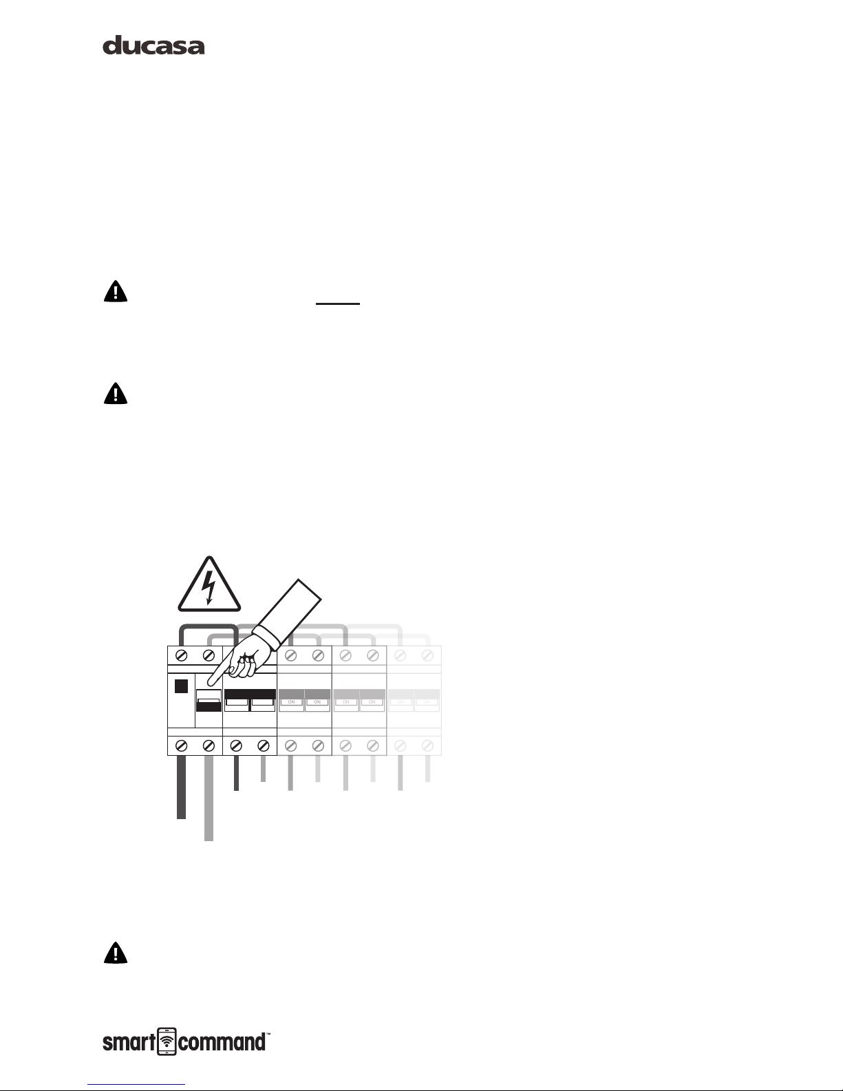
Preliminary considerations
The Energy Monitor must be installed by a
qualied electrician who should disconnect the
mains power in your home before commencing
work.
According to instructions, it must be possible
to isolate the electric power supply circuit of the
electric measurer +e using an omnipolar cut-off
element, either with a switch or circuit breaker.
The contact opening must be at least 3mm.
Preliminary considerations
The warnings safety symbol means
ATTENTION! PAY ATTENTION!
TEST
OFF
ON ON
ON ON
ON ON
ON ON
5
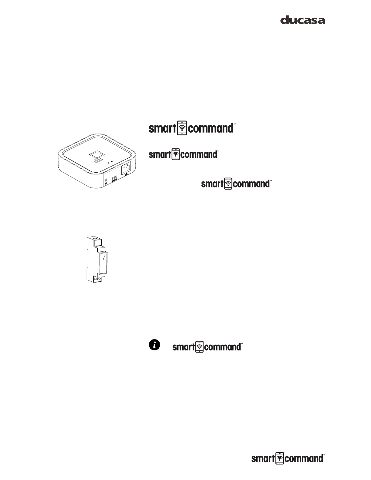
Contents of the
Pack.
Gateway, communicates with your
heaters wirelessly and
connects to the Internet via your router. This allows
you to control your devices from anywhere in the
world via the APP which is
available for Android and Apple devices.
Energy Monitor Sensor +e (optional): Measures
the electricity consumed in your home and sends
the information to the Gateway. You can then use
the APP so you see how and when you are using
electricity, helping you control your consumption
and reduce your energy bills.
System is distributed
in different packs with some or all of the devices.
Follow the instructions for installing the elements
that you have acquired.
Termoweb System Elements
6
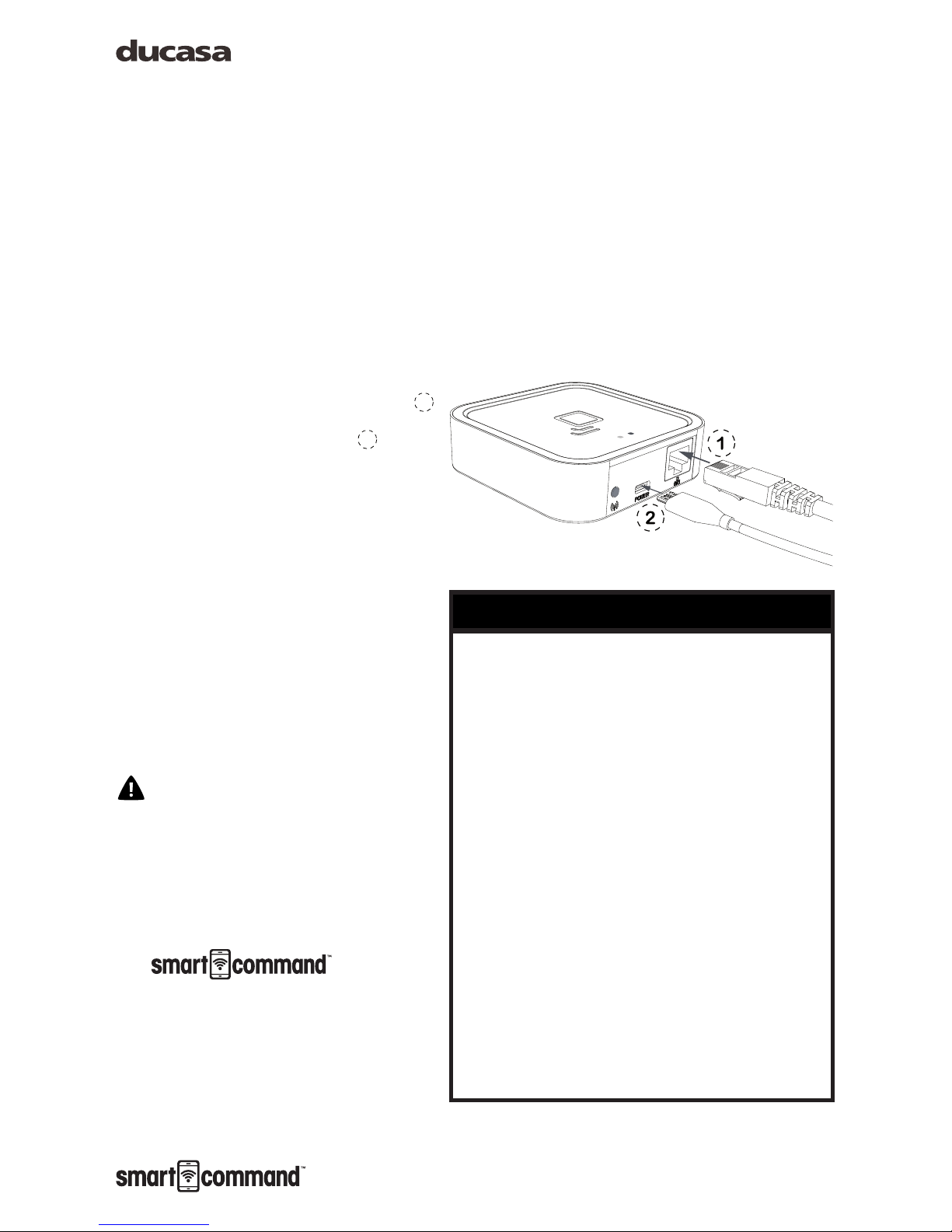
Installation instructions
Gateway
Connect the Gateway to the Internet
router using the Ethernet cable
1
Connect the USB cable 2 to the
Gateway and the other end to the
supplied power adaptor.
Wait two minutes then check the
LED lights on the Gateway to
check that it is communicating
correctly with the router.
It is preferable to register the
Gateway before installing it. If
it is registered after installation,
it may take a few minutes to be
accessible from the web page. If
you do not want to wait, disconnect
and connect the power supply to
the Gateway.
micro USB
ethernet
orange
green
The Gateway status is indicated by the LED lights:
Green off, orange ashing one second:
discovery status (device pairing).
Orange on, green ashing 0.2 seconds: the
router has not assigned an IP address to the
Gateway.
Orange on constantly, green ashing briey
every 5 seconds: the Gateway has connected
to router correctly, but there is no communication
with the Internet.
Orange on, alternating with green ashing
briey every 5 seconds: the Gateway has
connected to router correctly and has internet
connection.
Status of Gateway lights
Installation instructions

7
• To operate correctly the Gateway needs an Internet
connection via a broadband router. The equipment can
operate with broadband networks, cables and others, and in
most cases, no set up in the router is necessary.
• If there are any connection problems or if operating in
a corporate network, check with an IT technician that the
following requirements are met. As a general rule it is not
necessary to modify these parameters in a domestic router:
» The DHCP server in the router must be activated.
» There must be a direct Internet connection, without
passing through a proxy.
» The output ports must be open:
˃ 123 UDP
˃ 3000 TCP
Requirements for correct operation
Installation instructions

8
Energy Monitor (optional)
The installation of the Energy Monitor
should be carried out by a qualied
electrician.
Switch off the mains power supply in
the consumer unit. Disconnect the circuit breaker
where you are going to make the connection.
Connect the power supply cable to the Live and
Neutral terminals (L and N) of the Energy Monitor.
Place the Energy Monitor in the DIN rail in your
consumer unit where there is available space.
1
Connect the other two ends of the Energy Monitor
cable to the output of a circuit breaker, preferably
a lighting type, minimum 5A/230V, 2 . The circuit
breaker must be easy to access and be marked
so that it can be recognised as the Control Centre
isolator.
Connect the jack plug of the Energy Monitor
sensor to the socket on the top of the Energy
Monitor.
3
Open the sensor as indicated in the image 4 and
place it around the main power supply cable of
the consumer unit. NOTE: The Energy Monitor will
measure the electrical consumer of your complete
home, not just the heating.
Installation instructions
TESTTEST
4
L N
3
1
2
9
Installation instructions
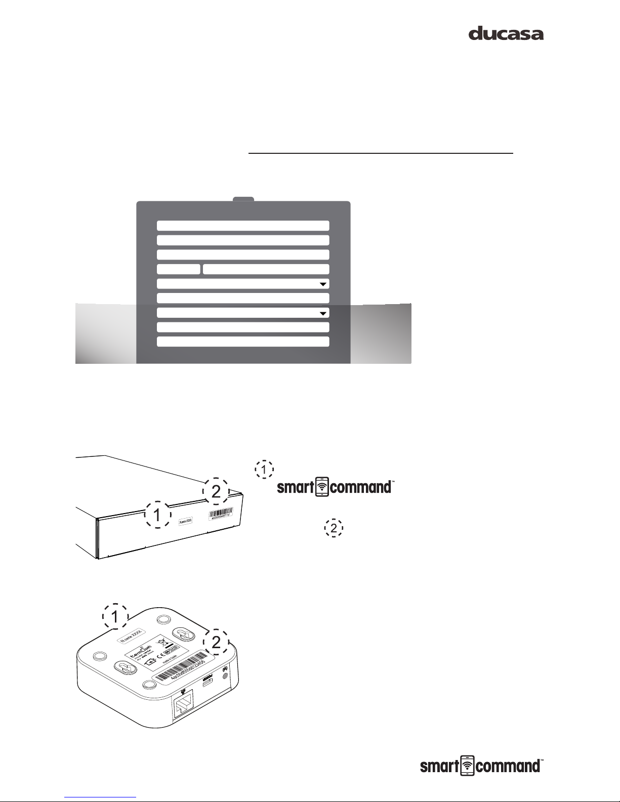
Registering the Gateway in the
web portal
Once all the components are installed as described
above, access the web portal at:
https://ducasa.co.uk/smartcommand/register and
select create a new account.
Fill in the elds indicated in the form:
User: enter your e-mail address.
Password: enter a password for accessing the
system, then conrm it in the following eld.
Serial No.: this appears at the bottom of
the Gateway and on the
packaging - it is a 4 digit number.
Device No.: this also appears at the bottom of
the Gateway and on the packaging - it contains
18 alphanumeric characters.
Location: this will help us determine the
equipment time, time zone and location for
weather forecasts.
Once the data registration is complete, press
REGISTER. In a few minutes you will receive
an e-mail conrming the account. If you do not
receive an email check your SPAM folder. When
you receive the email conrm registration by
clicking enclosed link.
REGISTERBACK TO LOGIN
Log
User (Email)
Password
Password confirmation
County
City
Home name
Country
Postcode
Serial number
Device ID
Login Termoweb
hps://control2.termoweb.net/?newuser=true
hps

10
Downloading of the App
When you registered your Smart Command
Gateway download the app,
which is available from:
https://ducasa.co.uk/smartcommand/app
With the App you can rename the radiators i.e.
Living Room, Kitchen etc, set the comfort and
economy temperatures, programme individual
times of operation for each heater, monitor the
energy use for home and each heater, monitor
room temperatures and much more.
The App is intuitive and with a few minutes
exploring you will soon become aware of the
features and benets of the
Gateway.
Installation instructions

11
Pairing
Gateway
Once the Gateway is connected to the Internet
and registered in the web portal, the devices must
be paired to it. To do this, put the switchboard
in discovery status by pressing the pairing key.
3. The orange LED starts to ash.
Once the pairing button has been
pressed, you have one minute to
add a device: for each new device,
the time available increases.
Energy Monitor (optional)
To pair the Energy Monitor, press the small push
button 4on the top of the Monitor with the paper
clip supplied. Look at the measurer LED to check
that it is paired.
Installation instructions
micro USB
ethernet
orange
green
3
• Not paired: LED off
• Paired correctly: the LED ashes once every two and a half
seconds.
• Paired but lost: the LED ashes once every half a second. This
happens when the Gateway is disconnected. Once communication
with the Gateway becomes available, the Energy Monitor will
connect again automatically.
Status of the Energy Monitor LED
4

12
Installation instructions
Avant DGi Radiator / Vitro-i
To pair the radiator press the OK key for 3 seconds
until the symbol appears in the top right of the
radiator screen.
MODE
PROG.
CONFIG.
3sec.
3sec.

13
Technical characteristics
Gateway
• Desktop or wall placement
• Power supply: 5V 500mA micro USB
external current adapter
• Dimensions: 80x80x22mm
• RJ45 connector for Ethernet connections
• Communication frequency: 868Mhz
• Operating temperature 0 ºC to 60 ºC
• Storage temperature -20 ºC to 85 ºC
Energy Monitor
• DIN rail placement. 1 rail module necessary
• Power supply 200-260 V ~ 50 Hz
• Consumption 0.90W
• Communication frequency: 868Mhz
• Measurement: CAT II
• Voltage and Current, up to 80A-AC
• Instantaneous active power
• Accumulated Active Energy
• Error: <3%
• Operating temperature: 0 ºC to 60 ºC
• Storage temperature -20 ºC to 85 ºC
• Impact strength: IK06
Current Sensor
• External current transformer with
measurement range between 0 and 100A
AC. Connection with 3.5 mm jack
• Cable measurement capacity: ø12mm,
maximum commercial section 95mm
2
If the equipment is used in a way not
specied in this manual, the protection
ensured by the equipment may be
compromised.

14
Notes about installation

15
Notes about installation
Processing electrical and electronic equipment at the end of their service life
(applicable in the EU and in countries with selective waste collection systems).
This symbol on your equipment or its packaging indicates that this product cannot be
treated as normal domestic waste, and instead it must be delivered to the corresponding
group that collects electric and electronic equipment. By making sure that this product
is disposed of correctly, you are helping to prevent the negative consequences for
the environment and human health that could be derived from handling this product
incorrectly. Recycling materials helps to preserve natural resources. To receive detailed
information about recycling this product, please, contact your Town Hall, nearest
collection point or the distributor where you acquired the product.
https://www.ducasa.co.uk
Telephone number for technical assistance: 01603 897 608
Advanced Heating Technology
 Loading...