

Page 1
Split Aire Acondicionado
MANUAL
MODELOS:
MULTI INV 183 E
MULTI INV 243 E
MULTI INV 283 E
Gracias por elegir nuestro aire acondicionado, para un correcto funcionamiento por favor lea detenidamente este manual antes de instalar o utilizar
el equipo y guárdelo para futuras consultas.
DE INST.
Page 2
CONTENTS
1
In line with the company’s policy of continual product improvement, the aesthetic and dimensional characteristics, technical
data and accessories of this appliance may be changed without notice.
CONFORMIT Y AN D RANGE
The air conditioner you have purchased is in conformity with the following American
Directives UL1995:
GENERAL INFORMATION
GENERA L INFORM ATION
1
4
4
5
5
6
Electrical Connections
Installing The Outdoor Unit
Maintenance
Installation Dimension Diagram
Check After Installation
Bleeding
INSTALLER
Please read this owner's manual carefully before
Only use the air conditioner as instructed in this
booklet. These instructions are not intended to
cover every possible condition and situation. As with
any electrical household appliance, common sense
and caution are therefore always recommended for
installation, operation and maintenance.
operating the unit and keep it carefully for consultation.
The products in this manual may be different with the real one, according to different
models, some models have displayer and some models without displayer, the position
and shape of the displayer please refer to the real one.
Page 3

Note: the above gures are only intended to be a simple
diagram of the appliance and may not correspond to the
appearance of the units that have been purchased.
Wrong wire connection may cause malfunction of some
electric components. After xing cable, ensure that
An all-pole disconnection switch having a contact
separation of at least 3mm
in all pole should be
connected in fixed wiring.
leads between connection to xed point have some space.
2
.
3.
4.
5.
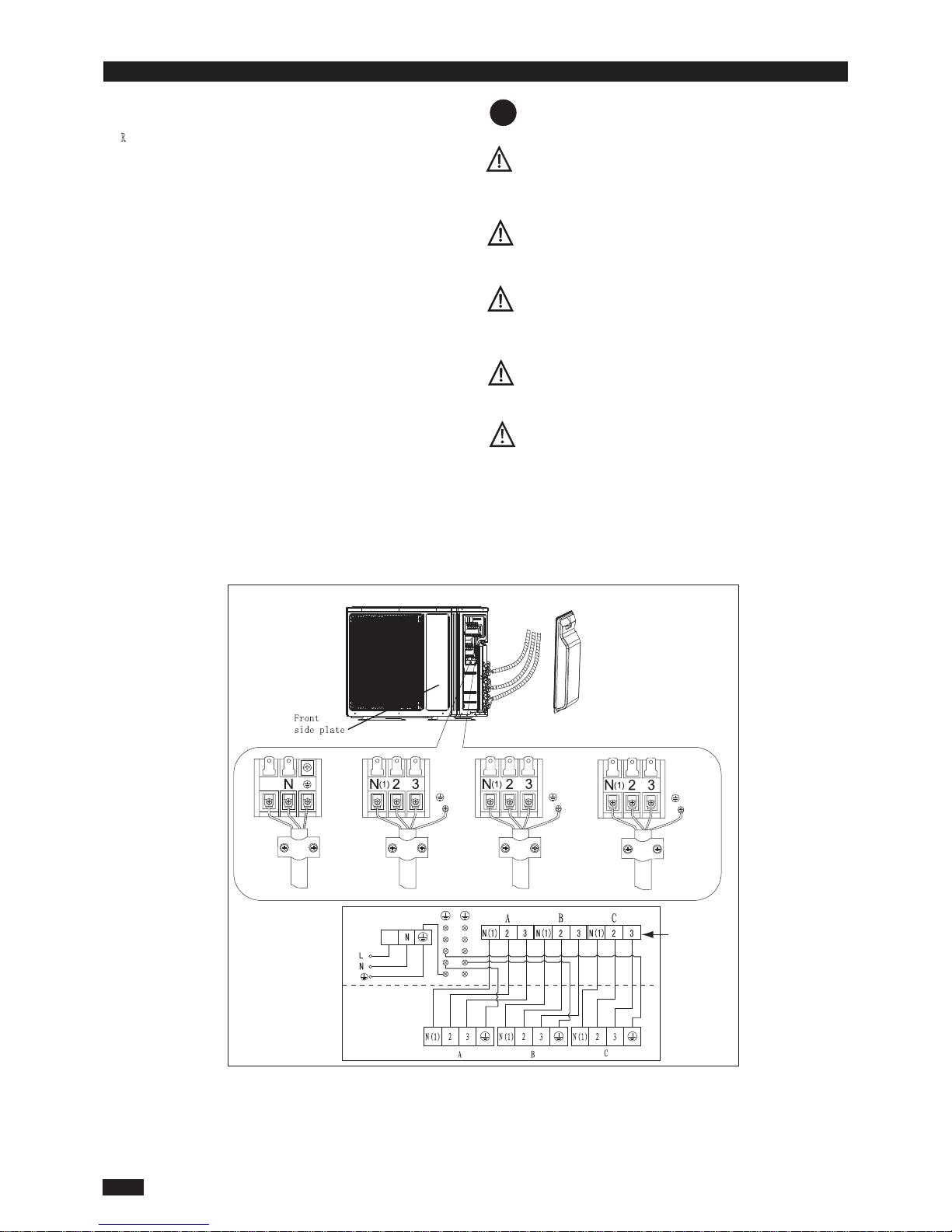
Remove the cable clamp, connect the power connection
1. R
emove the handle at the right side plate of the
outdoor unit (one screw).
the connection. The fitting line distributing must be
Wiring should meet that of indoor unit.
Fix power connection wire by wire clamp.
Ensure wire has been fixed well.
Install the handle.
cable with the terminal at the row of connection and
fix
consistent with the indoor unit. terminal of line bank.
ELECTRICAL CONNECTIONS
INS TALLER
The connection pipes and the connectiong wirings of
the unit A and unit B must be corresponding to each
other respective.
The appliance shall be installed in accordance with
national wiring regulations.
MULTI INV 183 MULTI INV 243
Handle
L
N
To the power supply
To unit B
connecting
Power
cord
To unit A
connecting
Power
cord
L
L
MULTI INV 183E:
Handle
L
N
To the power supply
To unit B
connecting
Power
cord
To unit A
connecting
Power
cord
L
L
MULTI INV 243
1
Page 4
2
Wrong wire connection may cause malfunction of some
electric components. After xing cable, ensure that
An all-pole disconnection switch having a contact
separation of at least 3mm in all pole should be
connected in fixed wiring.
leads between connection to xed point have some space.
2
.
3.
4.
5.
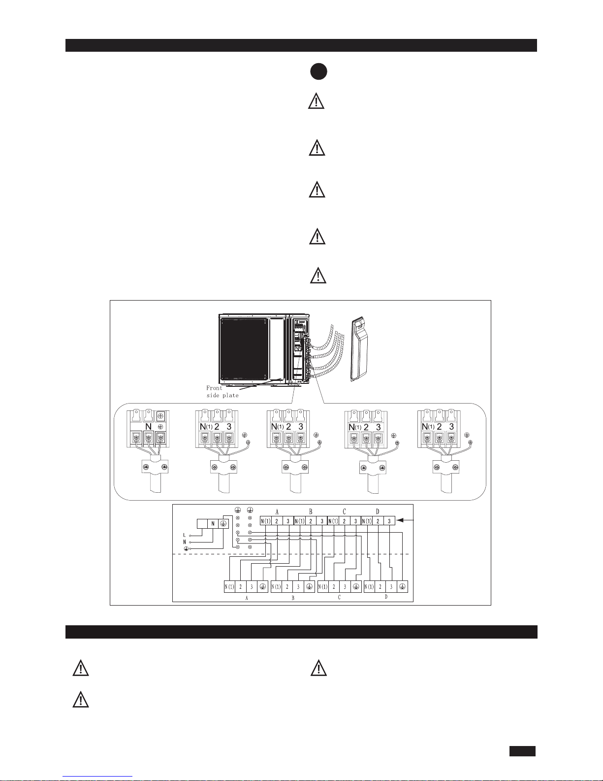
Remove the cable clamp, connect the power connection
1.
emove the handle at the right side plate of the
outdoor unit (one screw).
the connection. The fitting line distributing must be
Wiring should meet that of indoor unit.
Fix power connection wire by wire clamp.
Ensure wire has been fixed well.
Install the handle.
cable with the terminal at the row of connection and fix
consistent with the indoor unit. terminal of line bank.
ELECTRICAL CONNECTIONS INS TALLER
The connection pipes and the connectiong wirings of
the unit A ,unit B and unit C must be corresponding to each
other respective.
The appliance shall be installed in accordance with
national wiring regulations.
Do not install the outdoor unit where it is exposed
to the sunlight.
MULTI INV 243:
To the power supply
To unit B
Handle
To unit A
cable
interconnection
interconnection
cable
cord
Power
To unit C
interconnection
cable
Outdoor unit
Indoor unit
L
L
Note: the above gures are only intended to be a simple
diagram of the appliance and may not correspond to the
appearance of the units that have been purchased.
Page 5
Wrong wire connection may cause malfunction of some
electric components. After xing cable, ensure that
An all-pole disconnection switch having a contact
separation of at least 3mm in all pole should be
connected in fixed wiring.
leads between connection to xed point have some space.
2
.
3.
4.
5.
Remove the cable clamp, connect the power connection
1.
Remove the handle at the right side plate of the
outdoor unit (one screw).
the connection. The fitting line distributing must be
Wiring should meet that of indoor unit.
Fix power connection wire by wire clamp.
Ensure wire has been fixed well.
Install the handle.
cable with the terminal at the row of connection and fix
consistent with the indoor unit. terminal of line bank.
ELECTRICAL CONNECTIONS INS TALLER
3
The connection pipes and the connectiong wirings of
the unit A ,unit B,unit C and unit D must be corresponding
to each other respective.
The appliance shall be installed in accordance with
national wiring regulations.
Do not install the outdoor unit where it is exposed
to the sunlight.
HANDLING
After having removed the packaging, check that the contents are intact and complete.
The outdoor unit must always be kept upright.
Handling must be done by suitably equipped qualied
technical personnel using equipment that is suitable for
the weight of the appliance.
USER
MULTI INV 283:
Handle
To the power supply
To unit B
To unit A
interconnection
cable
interconnection
cable
cord
Power
To unit C
interconnection
cable
To unit D
interconnection
cable
Outdoor unit
Indoor unit
L
L
Page 6
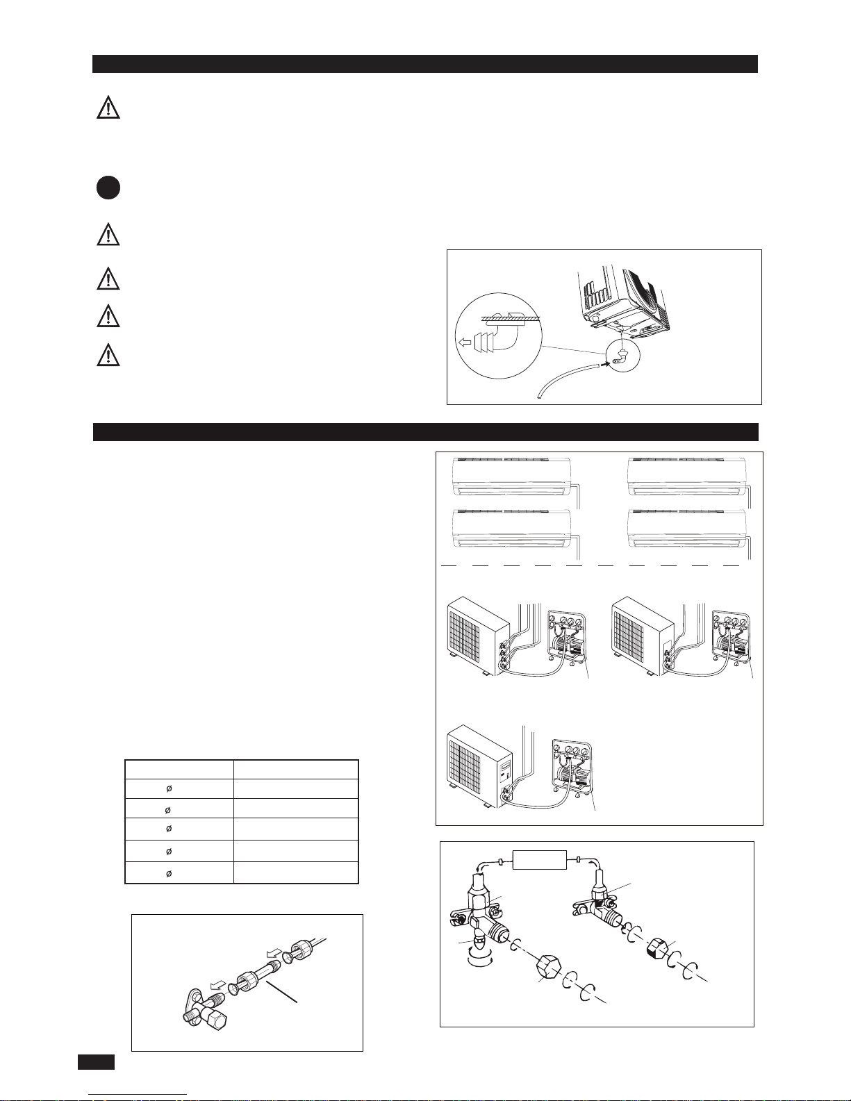
Use bolts to secure the unit to a at, solid oor.
When mounting the unit on a wall or the roof, make
sure the support is rmly secured so that it cannot
move in the event of intense vibrations or a strong
wind.
Do not install the outdoor unit in pits or air vents
Installin g the pipes
Use suitable connecting pipes and equipment for the
refrigerant R410A.
The refrigerant pipes must not exceed the maximum
lengths 10m.
Wrap all the refrigerant pipes and joints.
Tighten the connections using two wrenches working
in opposite directions.
Vacuum pump
INS TALLER
Humid air left inside the refrigerant circuit can cause compressor malfunction. After having connected the indoor
and outdoor units, bleed the air and humidity from the
refrigerant circuit using a vacuum pump.
(1) Unscrew and remove the caps from the 2-way and 3-
way valves.
(2) Unscrew and remove the cap from the service valve.
(3) Connect the vacuum pump hose to the service valve.
(4) Operate the vacuum pump for 10-15 minutes until an
absolute vacuum of 10 mm Hg has been reached.
(5) With the vacuum pump still in operation, close the
low-pressure knob on the vacuum pump coupling. Stop
the vacuum pump.
(6) Open the 2-way valve by 1/4 turn and then close it
after 10 seconds. Check all the joints for leaks using
liquid soap or an electronic leak device.
(7) Turn the body of the 2-way and 3-way valves. Discon-
nect the vacuum pump hose.
(8) Replace and tighten all the caps on the valves.
BLEEDIN G INS TALLER
INDOOR
UNIT
Install the drain tting and the drain hose (for
model with heat pump only)
Condensation is produced and ows from the outdoor unit
when the appliance is operating in the heating mode. In order
not to disturb neighbours and to respect the environment,
install a drain tting and a drain hose to channel the condensate water. Install the drain tting and rubber washer on the
outdoor unit chassis and connect a drain hose to it as shown
in the gure.
Vacuum pump Vacuum pump
Connect to the
indoor unit
INS T ALLIN G TH E OUTDOO R UNIT
Location
Twisting moment (N.m)
35-40
60-65
45-50
70-75
12
19
Diameter (mm)
9.52
16
15-20
6
18K unit need to be installed the indoor unit
conversion joint
Caution: Installation Must be Performed in Accordance
with the NEC/CEC by Authorized Personnel Only.
Refrigerant uid direction of ow
3-way valve
2-way valve
Service
inlet
(2) Turn
(8) Secure
(7) Turn to open fully
(2) Turn
(8) Secure
Valve cap
(6) Open by 1/4 turn
(7) Turn to open fully
(2) Turn
(8) Secure
Valve cap
18K MODE:
4
Page 7
Use suitable instruments for the refrigerant R410A.
Do not use any other refrigerant than R410A.
Do not use mineral oils to clean the unit.
MAINTENANCE
INS TALLER
INS TALLER
INSTALLATION DIMENSION DIAGRAM
The installation must be done by trained and qualified service personnel
with reliability according to this manual.
Contact service center before installation to avoid the malfunction due to
unprofessional installation.
When picking up and moving the units, you must be guidedby trained and
qualified person.
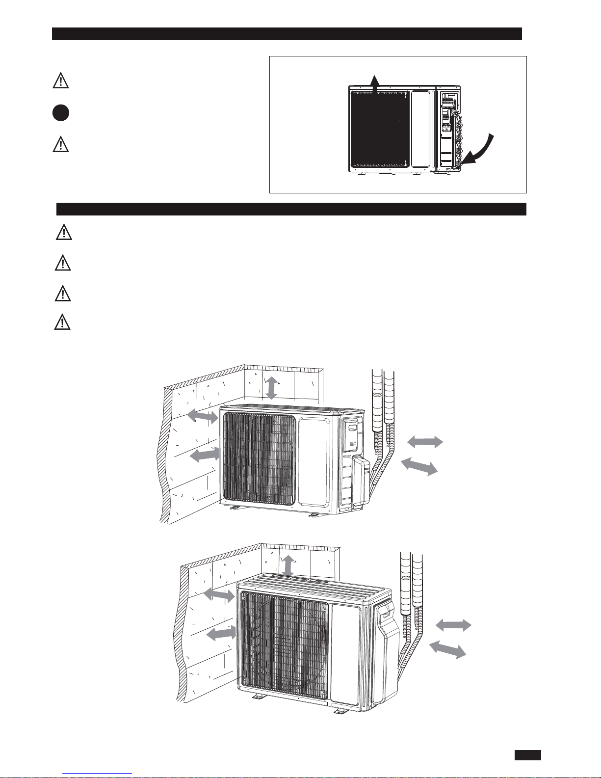
Ensure that the recommended space is left around
the appliance.
GWHD(24)NK3DO,GWHD(24)NK3EO,GWHD(28)NK3BO
30cm
Space to the cover
or abo ve
30cm
50cm
200c m
or more
Space to the cover
(Air inlet side)
or abo ve
or abo ve
Spac e to t he wa ll
(Air outlet side)
or above
50cm
GWHD(14)NK3BO,GWHD(18)NK3DO
30cm
Space to the cover
or abo ve
30cm
50cm
200c m
or more
Space to the cover
(Air inlet side)
or abo ve
or abo ve
Spac e to t he wa ll
(Air outlet side)
or above
50cm
This is just the schematic plan, please refer to the actual product.
5
Page 8
INS TALLER
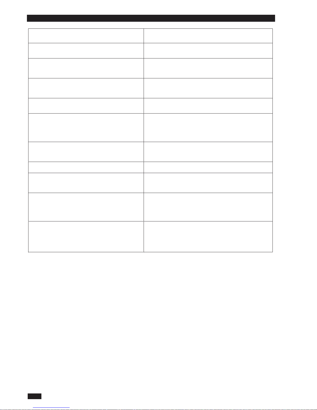
CHECK AFTER INSTALLATION
Check Items Problems Owing to Improper Installation
Is the installation reliable? The unit may drop, vibrate or make noises
Has the gas leakage been checked? May cause unsatisfactory cooling (heating)
effect
Is the thermal insulation of the unit
sufficient?
May cause condensation and water dropping
Is the drainage smooth? May cause condensation and water dropping
Does the power supply voltage accord
with the rated voltage specified on the
nameplate?
The unit may bread down or the components
may be burned out
Are the lines and pipelines correctly
installed?
The unit may bread down or the components
may be burned out
Has the unit been safely grounded? Risk of electrical leakage
Are the models of lines in conformity
with requirements?
The unit may bread down or the components
may be burned out
Are there any obstacles near the air
inlet and outlet of the indoor and outdoor
units?
The unit may bread down or the components
may be burned out
Have the length of refrigerating pipe
and refrigerant charge amount been
recorded?
It is not easy to decide the charge amount
of refrigerant.
6
 Loading...