

Ducasa DP 1300, DP 1500, DP 800, DP 1000, DP 600 Operating And Installation Manual
...
Thermal Electric Radiator
Operating and Installation Guide
Models
DP 600 DPLow profile 600
DP 800
DP 1000 DPLow profile 1000
DP 1300
DP 1500 DPLow profile 1500
E1400126
INSTALLATION
Main principles
This unit must be connected to a 230/240V 50/60 Hz power
supply.
This appliance must be connected to a junction box by its power
cord. Main installation must be provided by an omnipolar device
that distance between contacts must be minimum 3mm.
Power cord wires: blue wire neutral
brown wire phase
green-yellow wire earth
The replacement of the line cord, if necessary, should be made
by a professional service duly authorised by the Importer.
PRECAUTIONS TO BE TAKEN
The heater must be placed far from any inammable material
and should not be manipulated by unsurveiled children.
The heaters should by no means be covered by cloths or any
other material or object and should not be placed in a closed
furniture or place which might prevent the free circulation of the
air around the heater.
NOTICE
While in operation the unit must not be covered to avoid
overheating.
This unit is a Class I heater and should not be used or connected
in the wet area of a bathroom or kitchen.
Do not place radiator under a power socket.
Should the unit have to be repaired by a professional after sales
service, the panel board can be easily disconnected from the
heavy oil columns and sent out to the pertaining specialist.
Follow always security aspects, minimun distance from radiator
to side walls and top cover must be 150mm.
This unit should not be operated by any person with physical,
sensorial or mental limitations or don’t have the necessary
knowledge or experience except if they have received a specic
training or are accompanied by a responsible person (this applies
to the use of the unit by children).

The above notice also applies to the use of the unit by unattended
children.
The unit should be placed at a distance that makes impossible
for a person taking a bath or shower to touch the switches or the
thermostat unit.
This unit contains a precise amount ot the special oil inside the
nd and must only be opened, if needed, by the manufacturer or
by the authorised after sales service that should be informed in
case of leakage.
The standard rules about recycling and elimination of oil should
be followed once the unit will be no longer be used.
DIRECTIONS FOR THE INSTALLER
Electric power
The connecting wires should have the section required for the
distance, type of wire and unit size.
We recommend to place the connecting box at 10 cm to the right
of the unit and 15 cm to the oor.
The unit is equipped with a 150 cm long power cord without
plug.Depending on rules the electric circuit should be isolated by
means of an omnipolar cutting system either by switch or magnetothermic protecting device.
Placing the unit
The unit should be placed as close as possible to the coolest
wall in the room but it is not recommended to place it on a wall
that is not properly isolated and, in this case, the part of that wall
behind the unit should be isolated.In a bathroom, the unit must be
placed within the protected area and should not be reachable , direct or indirectly by a person in the shower or tub.The unit should
by no means be placed under a connecting plug.
Directions for the installation
The installation steps, as per above description, should be done
by qualied personnel only
Main components
The DP and DPL heat emitters consist of a special cast aluminium
body, specially designed for this purpose, to assure a maximum
rate of heat diffusion, the air circulation channels providing a very
effective convection effect.The aluminium body contains a special
heat conductor uid, lled inside the elements with a unique
procedure assuring a bubble-free content for a total uniform and
silent delivery of the heat produced by the single tube, hermetic,
electric resistance.
Operation
The control of the room temperature is assured by an electronic
thermostat in the control box placed at the side of the unit .
Switchin on
Turn on the switch F from position O to position I; a red pilot at
the right corner of the screen will lit.
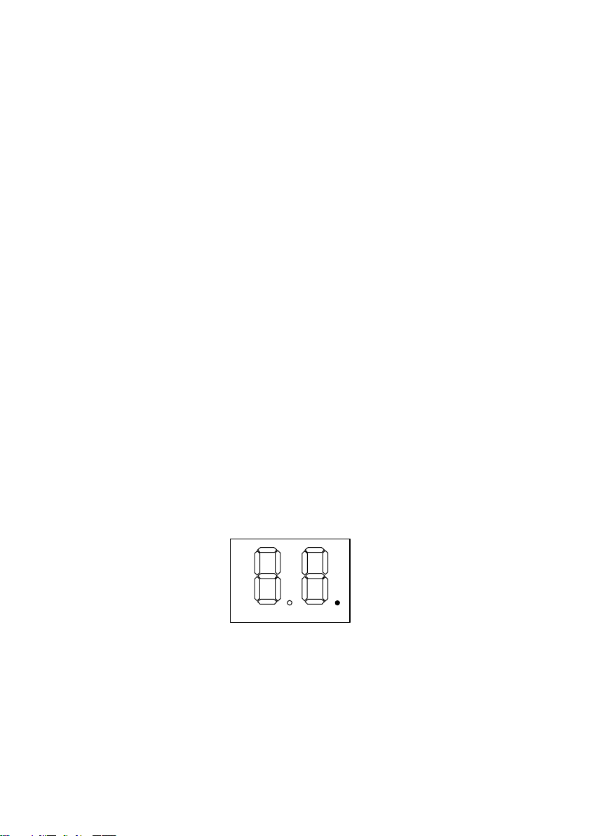
Starting off
When the main swith is turned on the thermostat stays at the
OFF mode showing a single illuminated dot as indicated in the
drawing:
 Loading...