

Ducasa Colorado TCR 140, Colorado MCR 40/120, Colorado MCR 40/140 Instructions For Operating And Installation
1
NOTE
A qualied electrician must carry out the electrical installation of this radiator. The electrical
installation must comply with current UK regulations. Any claim on the warranty could be invalid
if these requirements have not been met.
Electric Towel Radiator
Instructions for Operating and Installation
(Read these instructions carefully and retain for future reference)
Colorado MCR / TCR
Models
MCR 40/120 White
MCR 40/140 White
TCR 140 Chrome
v8 20180912 E1400240

2
CONTENTS
General Information page 3
Installation Instructions page 5
Electrical Power Supply
Location Of Towel Radiator
Mounting The Towel Radiator
Operating Instructions page 7
Controls
Mode Indicator Table
Function Modes
Maintenance And Guarantee page 16
3
GENERAL INFORMATION
Manufactured in steel, with a white or chrome nish, the Colorado towel radiator is simple to
t and maintenance-free.
Fast to heat up and fully programmable either directly into the towel rail or by using the
optional remote control.
• Designed and fabricated in accordance with EN 60335-1, EN 60335-2- 43 and EN
55014 (regulations for domestic appliances)
• Standard colour White (RAL 9016) or Chrome
• NEC Class II and IP44 Rated
• 230V A.C.
• Wall mounted
• On-off main switch
• Regulation by electronic thermostat
• Comfort, Economy, Program, 2-Hour Boost, Open Window Detection and Frost Protection settings
• Overheat protection with safety cut-out
• Large backlit display.
• Programmable by infrared remote control (Ducasa Remote) – optional
• Fitted with connecting power cable 1200mm long (without a plug)
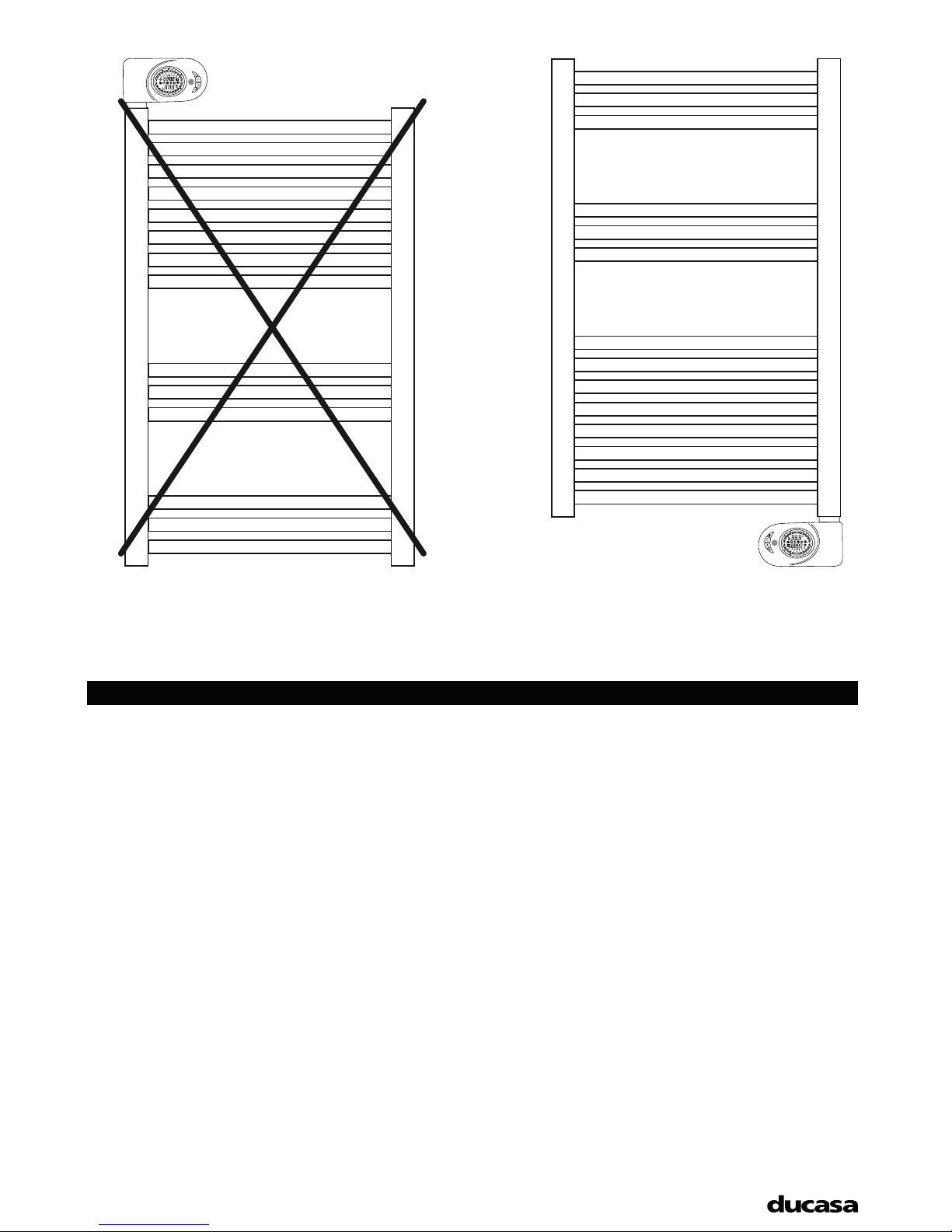
INCORRECT CORRECT
4
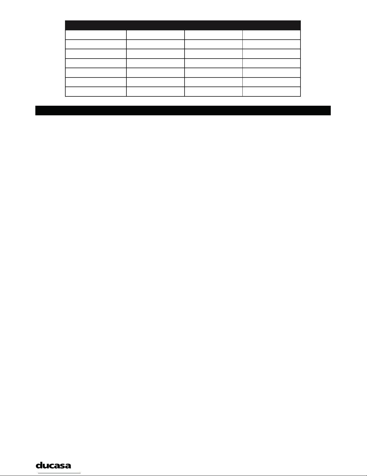
MODEL MCR 40/120 MCR 40/140 TCR 140
Wattage (W) 450 750 450
Power 230V/1/50Hz. 230V/1/50Hz. 230V/1/50Hz.
Weight (Kg.) 13 18 18
Dimensions (mm) 500 x 940 x 70 500 x 1400 x 70 500 x 1400 x 70
Class II II II
IP Rating 44 44 44
Cable (mm) 1200 1200 1200
IMPORTANT INFORMATION
See Section “Installation Instructions – Location of Heater” for important notes regarding the
siting of the appliance.
Due to the surfaces of the radiator becoming hot, it must not be positioned directly against
or below ammable surfaces.
This appliance is only intended for the drying of damp towels or clothes. Do not place
ammable objects (e.g. paper, magazines, spray cans, volatile substances or similar objects)
near or on the appliance.
WARNING: To avoid risks to very young children this appliance must be installed with the
lowest heated rail at least 600mm above the oor.
In case of breakdown or damage turn off the radiator at the main On/Off switch and notify
the supplier.
If the electricity cable gets damaged it must only be replaced by a technician appointed by
the manufacturer. This will avoid possible risks and ensure that special tools are available if
needed.
The radiator is lled with a precise amount of oil and in the event of leakage it must only be
opened, if needed, by the manufacturer or by the authorised after sales service.
Children of less than 3 years should be kept away unless continuously supervised.
Children aged from 3 years and less than 8 years should only switch on/off the appliance
provided that it has been placed or installed in its intended normal operating position and
they have been given supervision or instruction concerning use of the applince in a safe way
and understand the hazards involved.
Children aged from 3 years and less than 8 years should not plug in, regulate and clean the
appliance or perform user maintenance.
CAUTION — Some parts of this product can become very hot and cause burns. Particular
attention has to be given where children and vulnerable people are present.

5
INSTALLATION INSTRUCTIONS
ELECTRICAL POWER SUPPLY
A qualied electrician must carry out the electrical installation of this radiator. The electrical installation must
comply with current UK regulations. Any claim on the warranty could be invalid if these requirements have
not been met.
The radiator requires a 230V 50Hz power supply.
Connecting wires:
Brown: Live
Blue (or grey): Neutral
Black: Pilot wire (if required for external programmer)
NOTE: The towel rail does not require an earth wire.
IF PILOT WIRE IS NOT REQUIRED INSULATE BLACK CABLE TO ENSURE IT DOES NOT COME INTO
CONTACT WITH ANY OTHERS WIRES OR TERMINALS.
The connecting wires must be of the appropriate section, in regards to the length of cable, type of cable and
power rating of the apparatus.
The apparatus must be connected into a connecting box. According to regulations, the apparatus must be
connected to the power supply by means of an all-pole circuit breaker with a contact gap of at least 3mm or
by a thermal-magnetic circuit breaker.
LOCATION OF TOWEL RADIATOR
WARNING: To avoid risks to very young children this appliance must be installed with the lowest heated rail
at least 600mm above the oor.
It is essential to mount the towel radiator with the control box on the lower right hand side.
In bathrooms, the radiators must not be sited inside the protected area. The control unit switches must not be
reachable, directly or indirectly, by a person in the bath or shower.
The radiator, under no circumstances, should be installed below an electric power point.
MOUNTING THE TOWEL RADIATOR
The components for fastening the Towel Radiator to a wall are supplied in a bag together with the appliance.
There are four support assemblies, each consisting of the following components:
(A) 1 plastic tube Ø31 x 51mm + screw Ø3(F)
(B) 1 plastic tube Ø22 x 51mm with threaded inserts
(C) 1 screw M6
(D) 1 plastic retainer (conic 15º)
(E) 1 plastic cap
(F) 1 screw Ø3 x 10mm
(G) 1 screw Ø6 x 50mm
(H) 1 nylon stopper Ø10mm
The towel radiator is xed to the wall by four support assemblies. Two support assemblies should be positioned
between the 2nd and 3rd horizontal tubes from the top and two between the 2nd and 3rd horizontal tubes
from the bottom. At each level the supports should be spaced so that they are next to the vertical tubes at
each end.
 Loading...