

Ducasa AVANT-DGS 350, AVANT-DGS 500, AVANT-DGS 800, AVANT-DGS 1000, AVANT-DGS 1300 Operating And Installation Instructions
...
1
5.C22 (07/12)
E1400161
AVANT–DGS
Thermal Electric Radiator
Operating and Installation Instructions
(Read these instructions carefully and retain for future reference)
Models:
AVANT-DGS 350
AVANT-DGS 500
AVANT-DGS 800
AVANT-DGS 1000
AVANT-DGS 1300
AVANT-DGS 1500
AVANT-DGS 1800
NOTE:
A qualied electrician must carry out the electrical installation of this radiator. The Electrical
installation must comply with the current UK regulations. Any claim on the warranty could be
invalid if these requirements have not been met.

2
3
CONTENTS
General / Important Information Page 2
Installation Instructions Page 4
Electrical Power Supply
Location of Radiator
Mounting of Radiator
Operating Instructions Page 7
Controls
Switching On
Setting the temperature
Selection Of Mode
Programming
Keypad Locking (Anti-Tamper)
Maintenance and Guarantee Page 8
GENERAL INFORMATION
The Avant DGS has a special cast aluminium body specically designed to assure maximum rate of heat radiation; the
air circulation channels providing a very efcient convection effect.
Special heat conducting uid in the aluminium body. A unique process provides bubble free lling so that the uid
delivers warmth from the heating element in a totally uniform way, ensuring that the entire surface of radiator provides
comfortable heat.
Monotube heating element to ensure maximum heat output.
Designed and fabricated in accordance with EN 60335-1, EN 60335-2 and EN 55014 (regulations
for domestic appliances)
Standard colour White (RAL 9016)
Class I or Class II
Wall mounted (by quick xing system)
Capillary safety limiter
On-off main switch (illuminated)
Overheat protection
Key-pad locking (anti-tamper)
NTC electronic sensor
Fitted with connecting power cable 1450mm long (without a plug)
3
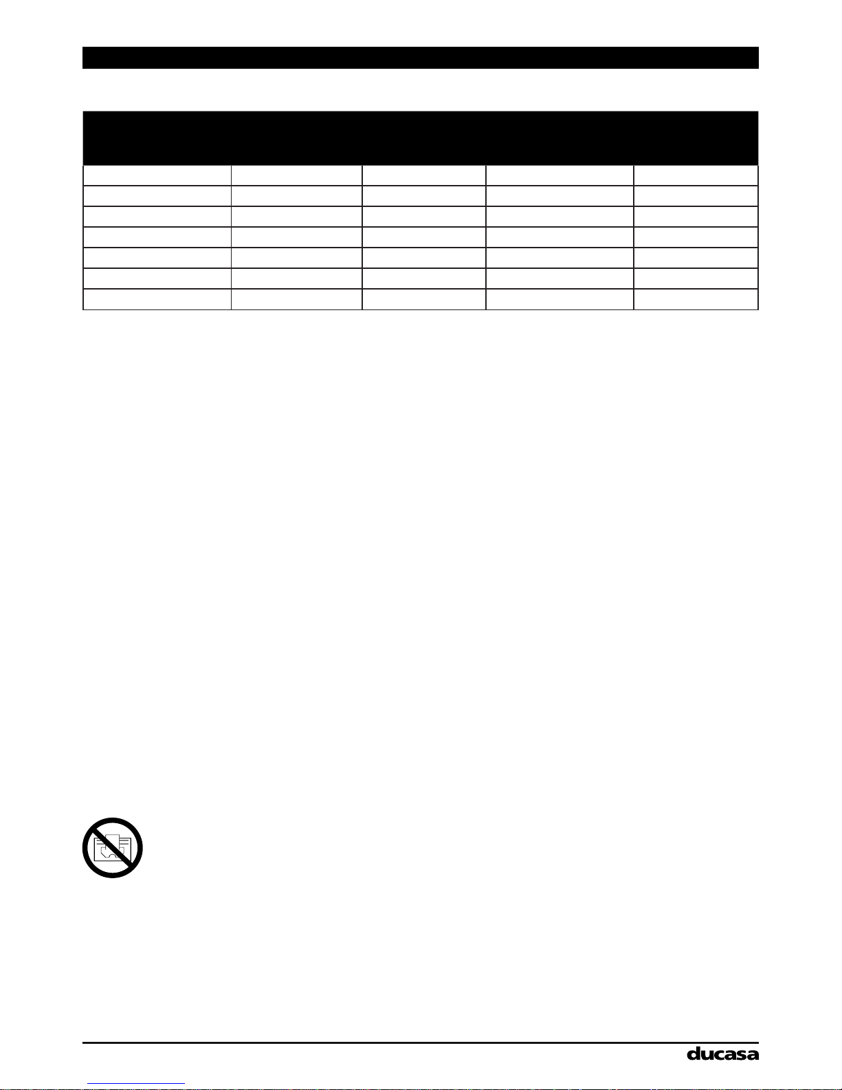
Technical Data
MODEL Number Of Fins
Power Rating
(W)
Size (mm) Net Weight (Kg.)
Avant-DGS 350 3 350 340 x 580 x 100 6.9
Avant-DGS 500 4 500 420 x 580 x 100 8
Avant-DGS 800 6 800 580 x 580 x 100 12
Avant-DGS 1000 8 1000 740 x 580 x 100 16
Avant-DGS 1300 10 1300 900 x 580 x 100 20
Avant-DGS 1500 12 1500 1060 x 580 x 100 24
Avant-DGS 1800 12 1800 1060 x 580 x 100 24
Important Information
See Section “Installation Instructions – Location of Heater” for important notes regarding the siting of the appliance.
Due to the surfaces of the heater becoming hot, it must not be positioned directly against or below inammable
surfaces.
Do not dry clothes or towels on the heater nor leave fabrics, magazines, spray cans, volatile substances or similar
objects within 250mm of the heater.
In case of breakdown or damage turn off the appliance at the main On/Off switch and notify the supplier.
If the electricity cable gets damaged it must only be replaced by a technician appointed by the supplier.
This will avoid possible risks and ensure that special tools are available if needed.
This appliance is not intended to be used by persons (incl. children) with limited physical, sensory or mental capabilities,
or who lack experience, except for those under supervision or have received instruction in the use of the appliance from
a person responsible for their security.
Children must be supervised in order to ensure that they do not play with the appliance.
WARNING: In order to prevent overheating, do not cover this appliance. There has to be free movement of air
around all surfaces of the appliance.
This symbol “DO NOT COVER”, is placed on the heater as a reminder to the user.

4
5
INSTALLATION INSTRUCTIONS
Electrical Connection
A qualied electrician must carry out the electrical installation of this radiator. The electrical installation
must comply with the current UK regulations. Any claim on the warranty could be invalid if these
requirements have not been met.
The radiator requires a 230/240V 50/60Hz power supply.
Connecting wires:
Brown: Live
Blue: Neutral
Yellow-green: Earth (only for Class I radiators)
The connecting wires must be of the appropriate section, in regards to the length of cable, type of cable and power rating
of the apparatus.
The apparatus must be connected into a connecting box.
We recommend that the connecting box is positioned 10cm to the right of the apparatus and at 15cm above the oor.
According to regulations, the apparatus must be connected to the power supply by means of an all-pole circuit breaker
with a contact gap of at least 3mm or by a thermal-magnetic circuit breaker.
Location
The ideal place to site the Ducasa radiator is as close as possible to coolest wall in the room but it is not recommended to
site the radiator on un-insulated exterior walls, in this case, the part of the wall behind the radiator should be insulated.
In bathrooms, the radiators must not be sited inside the protected area. The control unit switches must not be reachable,
directly or indirectly, by a person in the bath or shower.
The radiator, under no circumstances, should be installed below an electric power point.
Choose the location of the radiator in respect of the minimum distances that are indicated in Figure A.
window sill
150mm.
150mm. min.
unobstructed space each side
150mm.
Fig. A

5
Mounting The Radiator
Place the radiator on the oor, as shown in Figure 1. For radiators with 4, 6, 8 or 10 elements position the supports
supplied with the radiator as shown in Figure 1. For radiators with 12 elements the supports should be positioned
between the second and third elements on both sides.
Fig. 1
Fig. 2a
Fig. 3a
Fig. 2b
Fig. 3b
Place the supports between the elements as shown in Figure 2a, mark points on the walls through the xing holes as
shown in Figure 2b. This determines the spacing of the supports. Transfer these marks to whatever height above oor
(min. 150mm) that has been decided for the radiator. Fix the supports to the wall with plugs and screws. Be sure that the
supports are mounted in the correct position.
Lift the radiator and hang it on the supports, as Figures 3a and 3b.

6
7
Fig. 4
FREE LOCKED
As soon as the radiator is hanging on the supports press on the locking plate until a click is heard.
See Figure 4. The radiator is now installed.

7
Decrease Increase
OPERATING INSTRUCTIONS
Controls
The control of the room temperature is by means of an electronic thermostat in the control unit on the right hand side of
the radiator. The panel consist of two push-buttons and an LCD display. There is also a main On-Off switch on the right
hand side of the control panel.
set up temperature
heating indicator
Possible failures of the thermostat:
If the thermostat senses a temperature below -15ºC, you will see OC displayed on the screen.
If the thermostat senses a temperature above + 50ºC, you will see SC displayed on the screen.
Switching On
Once the radiator has been mounted on the wall and correctly connected to the main electricity power supply, press the
main On-Off switch.
During use, the control panel will display the set up temperature.
When the radiator is switched on, pressing the + and – buttons will increase/decrease the comfort temperature in
increments of 1ºC. Pressing and holding down either button will rapidly change the setting in increments of 1ºC; release
the button when the desired temperature is reached. Once the required temperature has been entered and there is no
further use of the + and – buttons, the control unit will automatically remember the selected temperature.
Temperature Compensation
Due to the characteristics of the radiator, the control unit has to read the temperature measurement from the lower part
of the apparatus, but it is automatically adjusted in relation to the comfort temperature setting. However it is possible to
manually adjust this “Thermic Compensation”.
Room temperature, recorded by an ambient thermometer minus Comfort setting (temperature) displayed on the control
panel screen = compensation value.
1. Press + button during switch ON with the main switch.
2. Press the + and - buttons to enter the adjustment in increments of 0.1ºC. ( from -7.0º to 7.0º)
3. If the keyboard is not used for 5 seconds, the thermostat will return to the normal mode.
Example:
A temperature 22ºC is measured in a room with a thermometer while the value of the required Comfort temperature
on the thermostat 20ºC.
The setting for the compensation is therefore: 22 – 20 = 2ºC.
In the temperature compensation mode, the user should put in: +2ºC.
Keypad Locking (Anti-Tamper)
The keypad can be locked to prevent any unauthorised person (children, people in public places, nurseries, ofces,
hotels etc.) altering the settings and programming in the control unit. To lock the keypad depress and hold the + and –
buttons at the same time. The screen will ash

8
MAINTENANCE AND CARE
Ducasa radiators require very little maintenance.
The surfaces of the radiator must not be cleaned with an abrasive product or those containing granular substances.
We recommend regular cleaning with PH neutral products.
In order to clean the radiator, it is recommended that the electric power is switched off.
Guarantee
Your appliance is guaranteed for 10 years against leakage and 2 years on electric and electronic components from the
date of purchase – during this period we will repair or exchange, at our discretion, any faulty or defective parts providing
the appliance has been used in accordance with the operating & installation instructions and has not been misused or
mistreated in any way.
Any unauthorised repair or attempted repair will invalidate the guarantee.
This guarantee is additional to your statutory rights.
In the unlikely event of a problem with your appliance please contact your supplier.
Correct Disposal of This Product
(Waste Electrical & Electronic Equipment)
(Applicable in the European Union and other European countries with separate collection systems)
This marking shown on the product or its literature, indicates that it should not be disposed of
with other household wastes at the end of its working life.
To prevent possible harm to the environment or human health from uncontrolled waste disposal,
please separate this from other types of wastes and recycle it responsibly to promote the
sustainable reuse of material resources.
Household users should contact either the retailer where they purchased this product, or their local government ofce,
for details of where and how they can take this item for environmentally safe recycling.
Business users should contact their supplier and check the terms and conditions of the purchase contract. This product
should not be mixed with other commercial wastes for disposal.
UK Distributor of Ducasa Products:
Heattend Products Ltd
Web: www.heattend.co.uk
Email: enquiries@heattend.co.uk
 Loading...