


OPERATOR'S MANUAL
MODEL : DG1500
DG3050
DG3500
DG4650
DG4950
DG5750
DG6500
DG7750
DG9250
DG11050
DG1500E
DG3050E(R)
DG3500E(R)
DG4650E(R)
DG4950E(R)
DG5750E(R)
DG6500E(R)
DG7750E(R)
DG9250E(R)
DG11050E(R)
WARNING: To reduce the risk of injury, the user must
read and understand the operator’s manual before using this
product.
SAVE THIS MANUAL FOR FUTURE REFERENCE

Table of Contents
Fore ward....................................................................................................3
Safety Precautions. ................................................................................... 4
Safety Specifications. ................................................................................ 5
Safety Regulation. ..................................................................................... 6
Warning Labels. .........................................................................................7
Product Specifications................................................................................8
Component Identification. ........................................................................9
Features. ....................................................................................................10
Operating Guide. ......................................................................................11
Operating......... .........................................................................................12
Power Management..................................................................................14
Maintenance..............................................................................................15
Trouble Shooting Guide...........................................................................18
Remote Start.............................................................................................19
Electrical Schematic Diagram.................................................................20
2

Foreward
Thank you for buying DUCAR generator unit. This product is a household generator which
produces electrical power by means of an engine driving a alternator, and is used in
situations where electricity supply is interrupted or as a primary source of power supply where
power is unavailable.
Please Read Instructions Carefully
If you DO NOT understanding any part of this manual, please contact DUCAR at:
www.ducar.com.cn. for any startup, operation and maintenance concerns. It is recommended that
you read this manual to understand all requirements and operating steps
of this generator before you use it. Keep this manual in good condition for reference in
case of emergency in the future. If you lend or sell the generator unit supply with this manual.
The generator can be operated in a safe, effective and reliable way only when it is kept, operated
and maintained properly. Before operating or carrying out maintenance of the generator unit, the
operator will:
Know well and strictly observe local laws and regulations.
Read the manual carefully and observe all safety warnings in this manual and on the generator.
Instruct others on the proper use of this generator and be sure they are familiar with all safety
warnings in this manual before use.
It is impossible for manufacturers to predict all possible dangerous situations, therefore, warnings in
this manual and labels on the generator unit may not identify all hazards. If no special suggestions
are raised with respect to the operation procedures, working procedures or operating skills, use
this generator in a manner which guarantees personal safety. In addition, make sure no damage to
the generator unit is caused by the operating procedures, working methods or operating skills.
Information contained here is based on the machine in production at time of publication.
TPE Australia reserves the right to change any parts described in the text without notice in advance.
Please read carefully the ALL safety warnings in the instructions and on the decals of the generator
unit, with symbol in front. Details are shown as follows:
Danger: You may cause yourself serious injury if you do not follow these warning labels.
Warning: You may suffer serious harm by ignoring this label
3

Safety Precautions
Danger: Use outdoors only, exhaust gas
released from the equipment contains Carbon
Monoxide (CO), which cannot be seen or smelt.
Excessive inhalation of CO may cause a loss of
consciousness and may claim life in extreme
circumstances.
Warning: Do not use this generator if
exposed to rain or if wet, and store in an
enclosed area when not in use.
Danger: Do not connect the
generator unit with mains supply or other
power sources , use it alone.
Warning: Properly ground the
generator and verify grounding is in
place before each use.
Warning: Keep the generator clean,
remove any gasoline or oil spills on or
around the generator.
Warning: DO NOT touch HOT
surface or you may be injured or suffer
burns.
4
Safety Specification
Danger: Electrocution hazard - Electricity can cause DEATH or SERIOUSINJURY
DO NOT use bare wire to connect power supply to electrical equipment, use a plug that
meets local regulations.
During generator operation, do not touch exposed wires.
During generator operation, keep children a safe distance from the generator unit.
DO NOT use the generator unless it is fully assembled as instructed in this manual.
Properly ground the generator and verify grounding is in place before each use. Grounding
regulations vary by location, consult a qualified electrician for verification.
Accessories including cables and plug must not be defective. Electric shock prevention
hinges on the breaker. If you renew the breaker use a breaker with the same rating and
performance features, contact your local authorized service agent.
Danger: Fuel used by the generator is combustible, as this equipment generates high
temperature, this causes a fire risk in some circumstances , such as refueling.
It is strictly prohibited to add fuel while the generator is operating;
When adding fuel, keep far away from any ignition source, and NO smoking;
When adding fuel, pay attention not to spill fuel on the equipment, if fuel is spilt;
clean it immediately, and only start it up when the spilt fuel has evaporated completely;
During operation, be sure there are no combustibles within a 2m range.
In case of long-term nonuse, make sure you use a fuel stabilizer or empty the fuel tank and
bowl.
Caution: This equipment contains high speed revolving parts, which may cause injury.
During generator operation, avoid coming into contact with any revolving parts.
During generator operation, observe surroundings, make sure there is no risk to the
generator, other people and nearby equipment.
During generator operation, do not lift or re-position. Turn the generator off ensuring it has
come to a complete stop.
Attention: operating requirements
Do not place weight on the equipment.
The wheel is adopted for convenience of equipment moving, do not use it in long distance,
otherwise it will be damaged.
Do not exceed rating power of the equipment in operation; otherwise, its service life will
be shortened. Power of common household appliances is shown on Page 14 in details.
Maintain the equipment based on requirements so as to prolong its service life, refer to
Page 15-17 for details.
Operate and store the generator in a dust free area this prevents dust entering inside of the
equipment which reduces its working life.
5
Safety Regulations
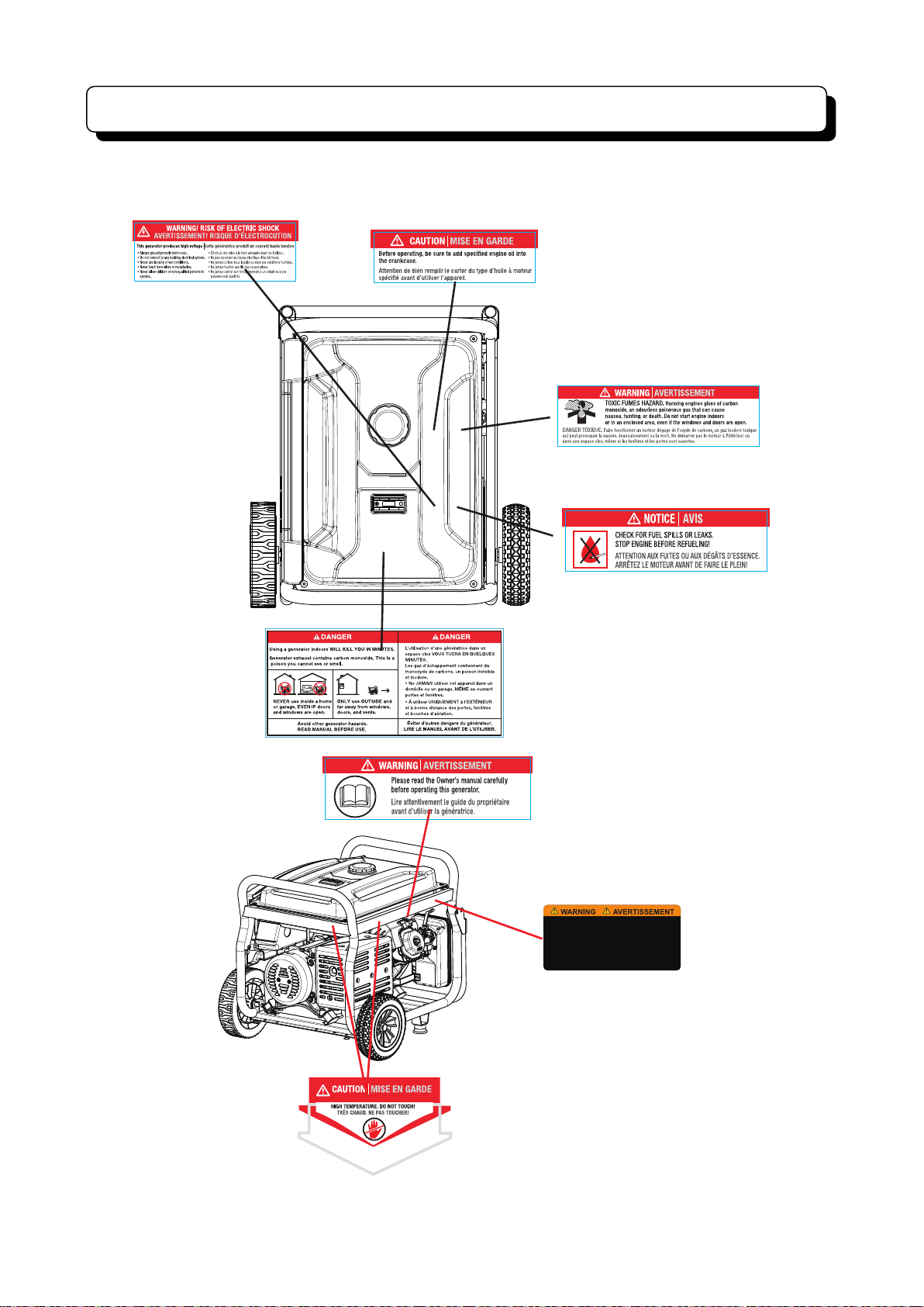
There is the warning decal on the machine to remind you of the safety regulations.
FOR ELECT RICAL EQ UIPMEN T ONLY/
POUR MATER IEL ELECT RIQUE SE ULEMEN T
FOR USE IN A WEATHE R PROTECT ED WELL VE NTILATED AR EA
EMPLOYE Z UNIQUEM ENT DANS UN EMPLACE MENT
A L'ABRI DES INT EMPERI ES ET BIEN AE RE
NEUTRA L BONDED TO F RAME
NEUTRE M IS À LA MASSE À LA CARCA SSE DU MOTE UR
DC SYSTEM FLOATING
DC RÉSEAU F LOTTANT
6
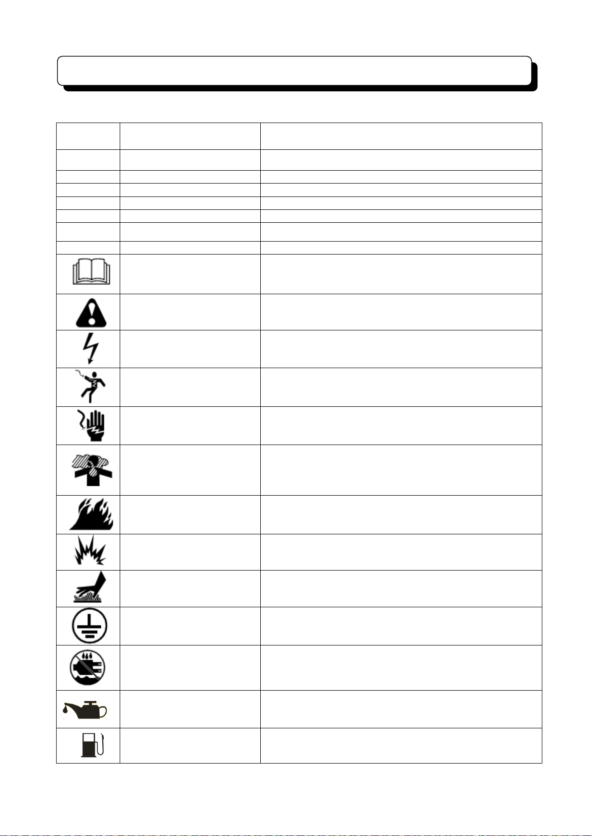
Warning Labels
Symbol
Name
Meaning
V
Volt
Voltage Unit
A
Ampere
Current Unit
Hz
Hertz
Frequency Unit (1Hz=60 r/min)
W
Watt
Power Unit
RPM
Revolution Per Minute
Speed Unit
PF
Power Factor
Generator Efficiency
G1
Performance Rate
Performance Rate
Read Instructions
Please read instructions carefully before using.
Safety Warning
Risk of harm in the case of not following instructions.
Electrocution Risk
Indicate that there is an electrified body here, pay attention to
safety.
Electric Shock
This is an electric device, failure to observe the indication
may result in an electric shock.
Electricity, Do Not Touch
The device produces electricity, do not touch during operation.
Toxic Gas
Exhaust gas from this generator contains Carbon Monoxide
(CO), a colorless & odorless gas. Excessive exposure to CO
may cause loss consciousness and may lead to death in
extreme circumstances.
Fire
High temperature generated from operation may cause fire,
so operate it with caution.
Explosion
If the fuel tank is exposed to high temperature or open fire it
may explode.
Burns
Some parts will generate high temperature in
operation, this will burn the skin.
Grounding
Consult an electrician to determine grounding. Make
sure the generator is safely grounded before
operation.
Water Exposure
Do not use a plug or electric device on rainy days or if
they are wet.
Engine Oil
Engine oil symbol and the specification is based on Page
9.
fuel
Fuel symbol.
Some of following symbols are used in the machine or the manual. To understand their meanings
will make it easy and safe for you in operation.
7

DG1500 DG3050 DG3500 DG4650 DG4950 DG5750 DG6500 DG7750 DG9250 DG11050
Model
DG1500E DG3050E(R) DG3500E(R) DG4650E(R) DG4950E(R) DG5750E DG6500E(R) DG7750E(R) DG9250E(R) DG11050E(R)
Frequency 60HZ
Voltage 120V 120V/240V
Power factor
Rated Power
Peak Power 1.50kW 3.05kW 3.50kW 4.65kW 4.95kW 5.75kW 6.50kW 7.75kW 9.25kW 11.05kW
Engine type 4-stroke OHV Air Cooled Single Cylinder
Engine oil
capacity
Product Specifications
Starting mode
Displacement 98 cc 208 cc
Fuel tank
capacity
1.40kW 2.50kW 2.80kW 3.60kW 4.00kW 5.00kW 5.50kW 6.25kW 7.50kW 9.00kW
0.4 L / 0.1 gal 0.6 L / 0.2 gal 1.0 L / 0.3 gal 1.2 L / 0.3 gal
Recoil /
Electric
6 L / 1.59 gal 15 L / 4 gal 25 L / 6.6 gal
Recoil / Electric start /
Remote start
/ 212 cc 224 cc 302 cc 420 cc 457 cc
1.0
Recoil /
Electric
Recoil / Electric start /
Remote start

Component Identifaction
AC Circuit Breaker
AC output
Oil tank cap
Wheel
Engine
switch
Fuel tank
Oil drain Plug
Handle & Grips
Recoil Starter Grip
Chock valve
Fuel Valve
Air filter
Control Panel
Muffler
Carburetor
Spark plug
Cylinder head
9

Features
KNOW YOUR GENERATOR
The safe use of this generator requires an
understanding of the information provided
inthis operator’s manual as well as a
knowledge of the project you are attempting.
Before use of this generator, familiarize
yourself with all operating features and safety
rules.
AC CIRCUIT BREAKER
The circuit breakers are provided to protect
the generator against electrical overload. The
circuit breaker may be reset by pressing
the circuit breaker reset button.
AIR FILTER
The air filter helps to limit the amount of dirt
and dust drawn into the unit during operation.
CHOKE LEVER
The choke lever is used when starting the
engine.
FUEL TANK
The fuel tank has a capacity of 15 liters / 25
liters
FUEL VALVE
Fuel flow from the fuel tank to the engine is
turned on and off using the fuel valve.Turn
fuel off after use.
GROUND TERMINAL
The ground terminal is used to assist in
properly grounding the generator to help
protect against electrical shock. Consult
with a qualified local electrician for
grounding requirements in your area.
LOW OIL SHUT DOWN PROTECTOR
The low oil sensor causes the engine to stop if
the level of oil in the crankcase is insufficient.
OIL CAP/DIPSTICK
Remove the oil fill cap to check and add oilto
the generator when necessary.
OIL DRAIN PLUG
When changing the engine oil, unscrew and
remove the oil drain plug to allow old engine
oil to be drained.
RECOIL STARTER GRIP
The recoil starter grip is used to start the
generator’s engine manually.
10

Operating Guide
Unit grounding
Shift the machine outdoors, use the grounding terminal connection wire to ground to earth. One
end of the wire is pressed below the butterfly nut on the unit, screw it up tightly, and the other
end is connected with the metal rod that is inserted into the ground.
Pre-operational
Add engine oil
Unscrew the oil dip stick, add engine oil
SAE10W/30 (oil requirements may vary
if operating in extreme temperatures, refer
above table). Fill the oil to the top of the thread
(indicated as "Correct Oil Level" above).
If oil is spilt wipe off machine to avoid fire
hazard and from the ground to avoid slipping.
Fill fuel oil
Do Not exceed this level
Open the fuel fill cap and fill with a Ethanol
Free
91 octane gasoline (95 and 98 octane
may
be used). The fuel level position will be
displayed on the indicator opposite the fuel cap.
When filling the tank the maximum fuel
position shall
the Fuel tank as indicated above.
Warning: keep away from any possible
ignition
source when filling gasoline; do not fill the fuel
tank while the generator is in operation.
not exceed the inner strainer of
Connect electric battery (electrical
starting only)
Connect the battery, red for positive terminal and
green for the negative terminal and make sure you
tighten the nuts. Pay attention and avoid contact
between positive and negative terminal to eliminate
the chance of short circuit. Make sure you place
the rubber protective covers over the terminals.
11

Operation
Starting the Engine
1. Unplug all loads from the generator.
2. Turn the Fuel valve to the ON position.
3. Move the choke lever to the C
NOTE: If engine has been operating and
is being restarted leave the choke lever in the
RUN position.
HOKE position.
b. For the manual start generator by pulling the
recoil starting grip unti
l the engine runs. NOTE:
Do not allow the grip to snap back after starting;
return it gently to its original place. Allow the
engine to run for 10-20 seconds, then move the
choke lever to the RUN position.
c. For remote start generator,the farthest distance
between remote control and generator is 50m.
Push the "START" button on the remote control
and the generator will start automatically.
REM OT E
START
START
STOP
STOP
4. Turn the switch on the control panel to ON.
a. The generator unit is electric.
start and can be started by
turning the switch around to
the START position. In order
to extend the service life of
the battery, do not turn the
switch for more than 3
seconds and the interval
between two attempts should
be at least 10 seconds apart.
5. To operate electrical equipment, turn the
circuit breaker ON. Please note that when using
several
appliances at the same time, do not add
the next one unless the generator and other
items are running normally. The total power of
the loads should not exceed the rated power of
the unit.
12

Operation
Stopping the Engine
1. Remove any load from the generator.
2. Turn the fuel valve to the OFF position.
To stop the unit quickly in an emergency:
Turn the engine switch to the OFF position.
Warning:
The surface tempe
are still high after shutdown, and it should
not be moved or touched before cooling
down to avoid the possibility of burns.
rature of the generator unit
3. a.Turn the engine switch to the OFF position.
b. For remote start generator,the farthest distance
between remote control and generator is 50m.
Push the "STOP" button on the remote control.
REM OT E
START
START
STOP
STOP
The
should be stored in a clean and dry
unit
place and should be protected from rain and
high temperature. Covering the unit is
recomm
ended to avoid excessive exposure to
moisture and dust.
If the generator is not used regularly remove the
fuel via the drainage bolt of the carburetor and
drain the fuel tank. Then tighten the oil drainage
bolt again. If a quality fuel stabilizer is used then
this procedure can be ignored.
13

Power Management
Electric equipment
Rated power(W)
Starting power(W)
Household
Appliances
Flat panel television
27"
500
800
Energy saving lamp
5~50
5~50
Electric cooker
1000
1000
Computer
800
800
DVD
100
100
Refrigerator
800
1600
Washing machine
300
600
Electric fan
50
100
Air-conditioner 2HP
1500
3000
Tools
Electric welder
2500
5000
Electric hammer
1000
1500
Water pump
800
1200
The starting wattage of some appliances are can be higher than the operating watts. Please read the
labels of the electric equipment for reference. The total power of the loads should not exceed the
rated power of the generator.
14

Schedule for
regular maintenance
Per
use
Every 20
hours or in
the first
month of
initial use (3)
Every 50
hours or
every 3
months (3)
Every
100
hours or
every 6
months
(3)
Every 300
hours or
every year
(3)
Engine oil
Inspect the
oil level
○
Replace
○ ○
Air filter
Inspect ○ Clean
○ (1)
Fuel strainer bowl
Clean ○
Spark plug
Clean ○
Replace
Valve clearance
Readjust
○ (2)
Cylinder head
Wash
Every 300 hours (2)
Fuel tank and
strainer
Wash
Every 2 years (2)
Oil tube
Replace
Every 2 years (2)
O il drain plug
Oil dipstick
Required oil level
Maintenance
Regular maintenance is the best guarantee of safe, economical and fault-free operation, and can also
contributes to environmental protection.
Maintenance schedule is as follows- Please carry out the recommended maintenance at the earlier of
the stated hours or elapsed time.
(1) Maintenance should be conducted more frequently if the unit is used in dusty conditions.
(2) Maintenance should be conducted by an authorized Stanley generator dealer
(to find one see tpeaustralia.com.au/dealers).
Replace the engine oil
15

Foam filter element
Air filter cover
Bolt
Air filter element
Strainer
O-type seal ring
Sedimentation glass
Fuel valve
Sedimentation glass
Maintenance
Clean the air filter
The air cleaner system uses a foam element that can be washed and reused.
1. Open the cover with the lock nut and remove the foam air filter element.
2. Wash the foam element in liquid detergent and water, then rinse in clean water and squeeze dry
in a clean cloth.
3. Saturate the foam filter with clean engine oil, remove excess by squeezing into a dry clean cloth.
4. Refit the air filter and air filter cover.
Clean the fuel bowl
1. Close the fuel valve and remove the sediment bowl. Take out the O-type seal ring and strainer.
2. Clean the sediment bowl, O-type seal ring and strainer with incombustible or high-flash solvent.
3. Reinstall the O-type seal ring and strainer, and tighten the sediment bowl.
4. Open the fuel valve and inspect for leakage.
16

Spark plug socket spanner
Spark plug cap
Feeler gauge
Maintenance
Clean the spark plug
Recommended spark plug models: NGK: BPR7ES. Champion RN7YC.
1 Remove the spark plug cap.
2 Clean the spark plug base.
3 Remove the spark plug with the spark plug socket spanner.
4 Inspect the spark plug insulator visually for damage. If it is damaged, replace a new one.
5 Measure the spark plug clearance with a feeler gauge. The clearance should be kept between
0.70 and 0.80mm.
6 Inspect if the washer of the spark plug is in good condition.
7 Reinstall the spark plug and tighten it with the spark plug socket spanner. Press down the
washer of the spark plug and place the spark plug cap.
Valve clearance (should be conducted by a professional person)
Remove the cylinder cover and measure the valve clearance with the feeler gauge. The clearances
are 0.1mm for the inlet valve and 0.15mm for the outlet valve.
17

Trouble Shooting Guide
Fault Cause Action
No fuel Fill the oil tank with gasoline
The unit can not
start
There is no power
output
The unit shudders
during operation
The unit emits
white smoke
The unit emits
black smoke
The Fuel valve is not turned
on
The Fuel valve is blocked Clean the fuel bowl (refer to page 16)
No engine oil or the engine
oil level is low
The engine switch is turned
off
The spark plug fails
The circuit breaker is in the
off position
The plug is poorly contacted Remove and refit the plug.
The choke lever position
is incorrect
The temperature of the engine
is too high, maybe overloaded
The fuel is contaminated Use fresh clean fuel
The air filter is dirty Clean the filter element of the air filter
The load is too heavy Reduce load to the rated limit
Turn the fuel valve to ON
Add oil
Turn the switch to the “on” position
Clean or replace the spark plug (refer to
page 17)
Turn the circuit breaker to the “on”
position
Move the choke lever to the “open”
position during operation
Let the engine run without load for more
than 10 minutes
The unit emits blue
smoke
The power
decreases
The environmental condition required to operate the generator:
·Suitable temperature: -15℃-40℃.
·Suitable humidity: lower than 95%.
·Suitable altitude: under 1,000 meters (The power load should be reduced where the generator is
used at altitudes greater than 1000 meters.)
The generator unit can only be loaded to the rated power under the specified environment
conditions. If the environment conditions are inconsistent with the above standards, or if the
cooling conditions of the engine and generator unit are poor; for example, when operating
in enclosed areas, it is necessary to reduce the power load. It is also necessary to reduce the
power load when the temperature, altitude or relative humidity exceed the standards.
If the generator does not work properly in optimal conditions, please take to the nearby
dealer or after-sales service center for inspection.
The engine oil is overfilled Drain oil to correct level
The engine oil type is
incorrect
The spark plug fails
The valve clearance are out
of adjustment
Choose appropriate engine oil model (refer
to page 11)
Clean or replace the spark plug (refer to
page 17)
Adjust the valve clearance (refer to page
17)
18

Remote start
Remote start:
Aim remote start the gasoline engine (distance between more than 50m).
Requirement:
. Turn off the machine manually after remote starting is acceptable;
1
2. Turn off the machine by remote key after manually start is acceptable;
3. Turn off the machine by remote key after remote start is acceptable;
4. Following is not acceptable when manually start and remote start:
(1) start
(2) turn off
(3) connect the fuel electromagnetism valve;
5. Once the remote start broken, manually start will be another option;
6. Remote start be useless after start;
7. After recoil start, remote turn off is acceptable;
Min. start voltage: 6.2V
When turn off by remote key, it should last 8 seconds.
Remote start should last 4seconds.
Please make sure the 12V (DC) line connect to battery bef
system will be damaged during machine running.
Battery use:
Aim remote start the gasoline engine (distance between more than 50m).
Requirement:
1. The specification of battery recommended: 12V,9Ah
2. Do not connect the anode and negative pole erroneously, when use the batter
3. The battery need to be injected electrolyte before us
4. The height of electrolyte need to be inspected each month. when the level is low, please inje
distilled water or pure water between upper and low level.
5. The battery need to be clean. If the electrolyte is spattered on the generator set,
the grounding and down-lead will be eroded. Please wash them with water if erosion.
1. The explosive gas will be happened when use the battery. So do not close with fir
ore starting, otherwise the remote start
2. The battery includes strong acid. Do not spatter battery on your skin or eyes. If it happen
wash it with waterright now. If serious, go to doctor for help.
3. Please note that if the battery is smirched by gasoline, oil or organic impregnan
the rind of the battery will be damaged.
19

Recoil Start
20

Recoil Start
21

Remote Start schematic diagram
R
M
V
A
+
-
22

Remote Start schematic diagram
23

Electrical schematic diagram
24

Recoil Start
2
5
 Loading...