

Ducane 95G1 Product Specifications
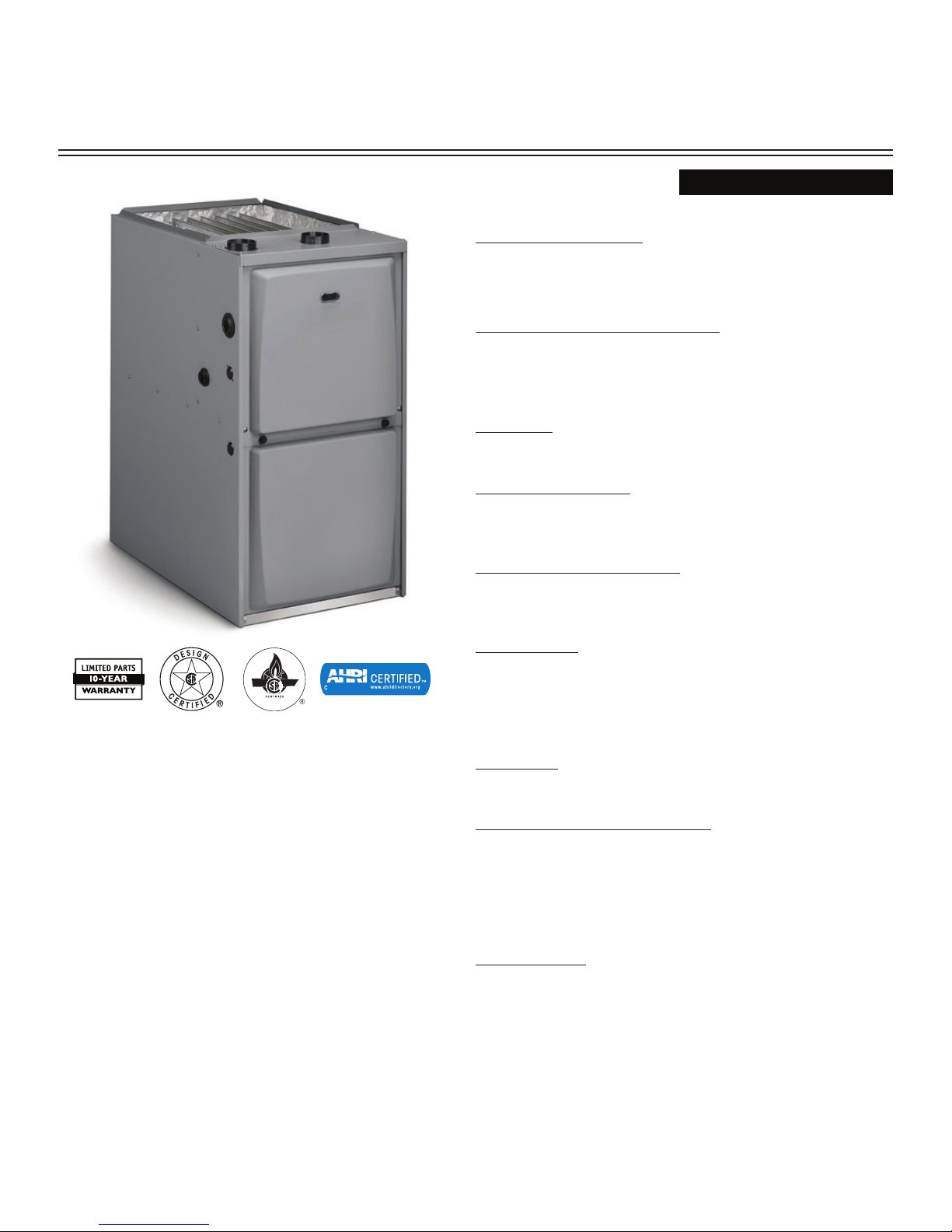
95G1
PRODUCT SPECIFICATIONS
SINGLE STAGE
GAS FURNACE
FORM NO. 95G1-100 (08/2015)
CONFIGURATIONS
• Upflow/Horizontal
• Downflow
HEAT EXCHANGER DESIGN
• Aluminized steel design primary heat exchanger with crimped no
weld construction
• AL 29-4C Stainless steel secondary heat exchanger
BURNER
• Aluminized steel inshop burners for smooth fit
CABINET DESIGN
• Compact 33" height
• Standardized widths for easy coil fit
AIR DELIVERY SYSTEM
• Multi-speed PSC blower motor
• Easily removable slide-out blower design
CONTROLS
• Single Stage Gas Valve
• Self diagnostics saves last 5 fault codes regardless
of power interruption
• Control features electronic air cleaner and humidifier terminals
VENTING
• Designed certified for direct and non direct applications
INSTALLATION FEATURES
• Left or right utility connection
• Designed certified for direct and non-direct vent applications
• Zero step horizontal conversion
• Removable floor base for bottom return air
WARRANTY
10 year limited parts warranty / lifetime heat exchanger warranty available.
See limited warranty document for details.
Page 1
95% GAS FURNACE 95G1
Page 2
PHYSICAL AND ELECTRICAL DATA
Model
Input
(Btuh)
Output
(Btuh)
AFUE
(ICS)
Nom.
Cooling
Capacity
Gas
Inlet
(in.)
Volts/
Hz/
Phase
Max.
Time
Delay
Breaker
or Fuse
Nominal
F.L.A.
Trans.
(V.A.)
Approx.
Shipping
Weight
(lbs.)
UPFLOW / HORIZONTAL
95G1UH045BP08 44,000 41,000 95.0% 1.5 - 2 1/2 120 - 60 - 1 15 3.1 40 121
95G1UH045BP12 44,000 42,000 95.0% 2 - 3 1/2 120 - 60 - 1 15 6.1 40 123
95G1UH070BP12 66,000 64,000 95.0% 2 - 3 1/2 120 - 60 - 1 15 6.1 40 128
95G1UH090CP12 88,000 85,000 95.0% 2 - 3 1/2 120 - 60 - 1 15 6.1 40 145
95G1UH090CP16 88,000 85,000 95.0% 3 - 4 1/2 120 - 60 - 1 15 8.2 40 148
95G1UH110CP16 110,000 106,000 95.0% 3 - 4 1/2 120 - 60 - 1 15 8.2 40 157
95G1UH110CP20 110,000 106,000 95.0% 4 - 5 1/2 120 - 60 - 1 15 10.0 40 163
95G1UH135DP20 132,000 126,000 95.0% 4 - 5 1/2 120 - 60 - 1 15 10.0 40 180
DOWNFLOW
95G1DF045BP12 44,000 42,000 95.0% 2 - 3 1/2 120 - 60 - 1 15 6 .1 40 125
95G1DF070BP12 66,000 64,000 95.0% 2 - 3 1/2 120 - 60 - 1 15 6.1 40 129
95G1DF090CP20 88,000 85,000 95.0% 4 - 5 1/2 120 - 60 - 1 20 11.5 40 148
95G1DF110CP20 110,000 106,000 95.0% 4 - 5 1/2 120 - 60 - 1 20 11.5 40 165
Note: For vent length and clearances to combustibles, please reference installation instructions.
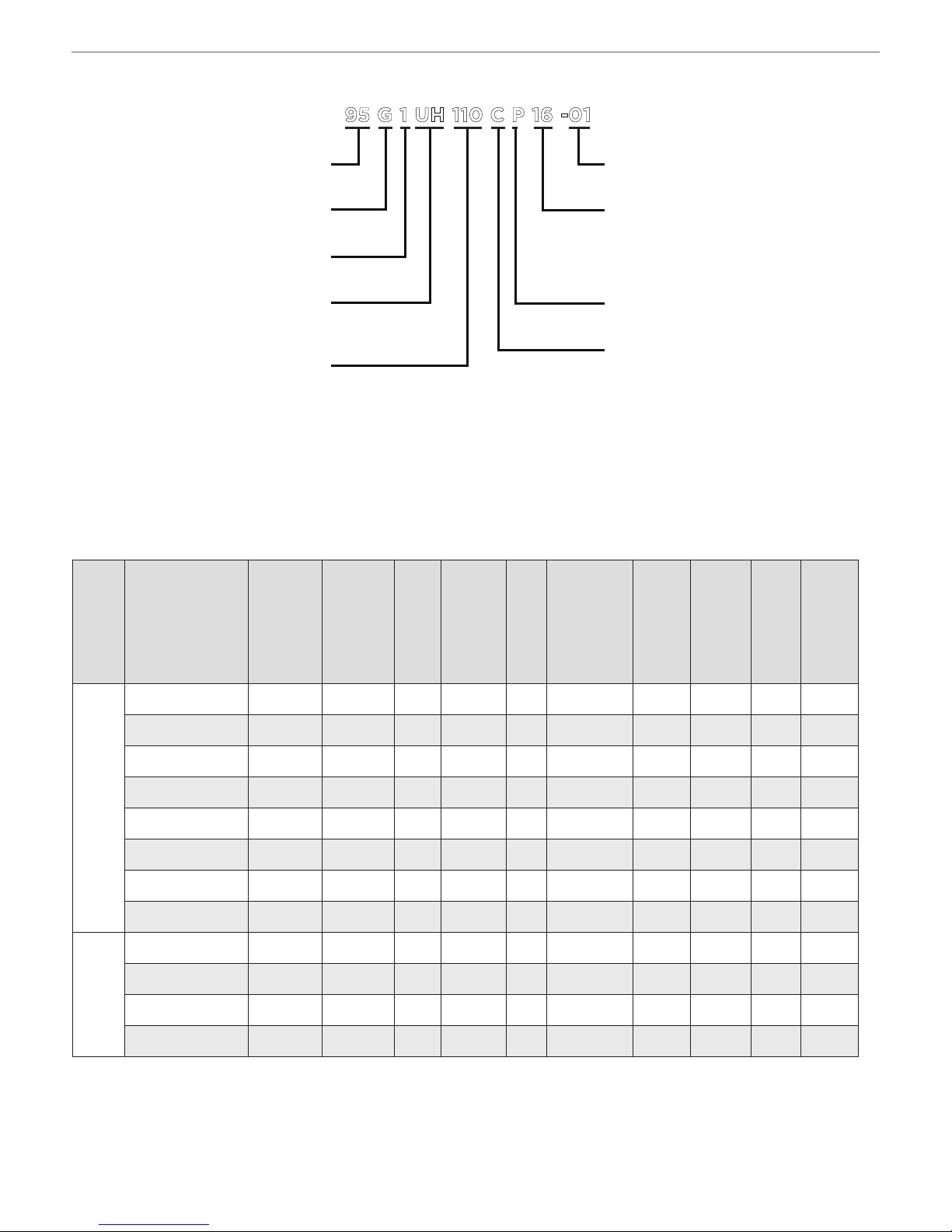
MODEL NUMBER GUIDE
NUMERIC CODE
REVISION CODE
NOM. CFM X 100
08 = 2TON ADD ON COOLING
12 = 3TON ADD ON COOLING
16 = 4TON ADD ON COOLING
20 = 5TON ADD ON COOLING
BLOWER DRIVE
P = PSC
CABINET WIDTH
B = 17.5” WIDTH
C = 21.0” WIDTH
D = 24.5” WIDTH
AFUE
95 = 95% EFFICENCY
GAS
G = GAS
STAGES
1 = SING LE STAGE
CONFIGURATION
UH = UPFLOW / HORIZONTAL
DF = DOWN FLOW
BTUH INPUT
HEATING INPUT X 1000
95 G 1 UH 110 C P 16 -01
 Loading...