

Page 1
HEAD OFFICE
Route de la Limouzinière - BP 41
44310 St PHILBERT DE GRAND LIEU
Phone: 02 40 78 97 22
Fax: 02 40 78 78 71
www.duarib.fr
Mail: [email protected]
D040369B
C0400227B
R O L L I N G S C A F F O L D I N G S
ASSEMBLY,
DISASSEMBLY AND
USE INSTRUCTIONS
Compliant with norm NF EN 1004
Compliant with Decree dating form 01/09/04
Page 2
ASSEMBLY, DISASSEMBLY AND USE INSTRUCTIONS
Compliant with norm NF EN 1004
Compliant with Decree dating form 01/09/04
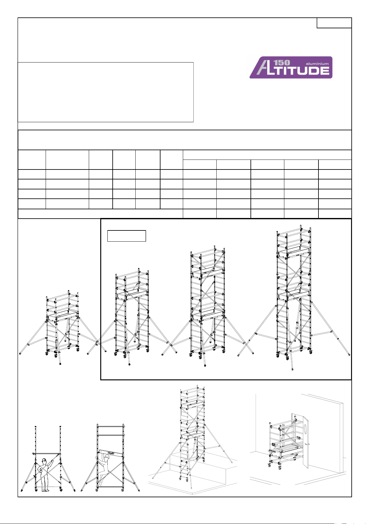
LOADING CONDITIONS
Floor: Maximum allowed load spread over the floor = 150 kg
Whole scaffolding: Maximum allowed load spread over the
floors = 300 kg
ALTITUDE 150
D040369B
Code
500802 1.8 m 3.8 m Class 3 54 Kg 1 1 376016602061 4
500803 2.8 m 4.8 m Class 3 59 Kg 1 1 1 376016602062 1
500804 3.8 m 5.8 m Class 3 82 Kg 1 2 1 376016602063 8
500805 4.8 m 6.8 m Class 3 86 Kg 1 2 1 376016602064 5
Gencod
500802
Floor
height
Work
height
(class 3 = 200 Kg/m² spread load)
NF EN 1004
500803
Load Weight
Parcel
500001 500006 500003 500004 500005
376016602011 9 376016602058 4 376016602013 3 376016602014 0 376016602015 7 Gencod
500804
500805
Safe asembly
Assembly on a difference
in level
4.8 m floor height 3.8 m floor height 2.8 m floor height 1.8 m floor height
Fitting through doors
Page 2/20
Page 3
D040369B
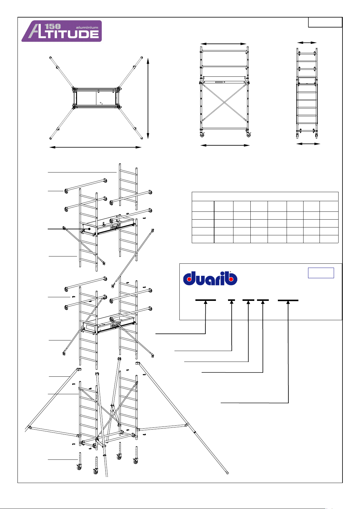
Center-to-center D Center-to-center E
Min dim. B
C257004
C257005
11307
C257003
C257010
Min dim. A
Overall C
Overall F
Dimensions
Code
Florr
Height
1.8 m 2180 1620 1570 1500 620 690 500802
2.8 m 2800 2260 1570 1500 620 690 500803
3.8 m 2960 2500 1570 1500 620 690 500804
4.8 m 3480 3040 1570 1500 620 690 500805
A B C D E F
Unit of measurement: mm
Head Office:
Route de la Limouzinière
44310 St Philbert de Grand Lieu
08067
EN1004 - 3 – 4,8/4,8 - XXXD Rolling
Follow the assembly and use instructions
Reference to the norm
C257008
Load evenly spread class
(class 3, 200 Kg/m²)
Maximum outdoor height use
Maximum indoor height use
C257009
Access via stairs: no
Access via step stairs: no
C257012
Access via tilted ladder: no
Access via vertical ladder: yes
C257001
Page 3/20
Page 4
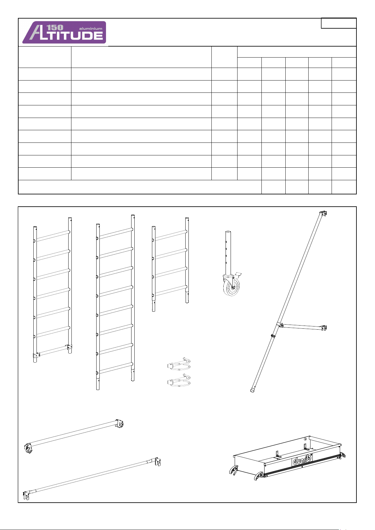
PARCEL CONTENT
D040369B
Code Description
C257001
C257012
C257003
C257004
C257005
11307
C257008
C257009
C257010
C257012
1.5m wide alu-wood floor with integrated toeboards 13
Ø125 wheel adjustment on 15 cm 1.6
1.765m x 0.62m base ladder 3.4
2m x 0.62m ladder 3.5
1m x 0.62m ladder 1.8
1.5 m handrail 1.2
Brace’s Lg: 2m 0.8
Stabilizer 3.7
Pin (bundle w/ 2 pins) 0.05
C257003
C257004
Weight
Kg
Parcel weight
C257001
Parcel
500001 500006 500003 500004 500005
4
2
1 2 3
2
2 4
1
2 2 4 4
4
4 1 2 3
36 Kg 17.8 Kg 5.2 Kg 10.4 Kg 14 Kg
C257005
C257008
C257009
C257010
11307
Page 4/20
Page 5
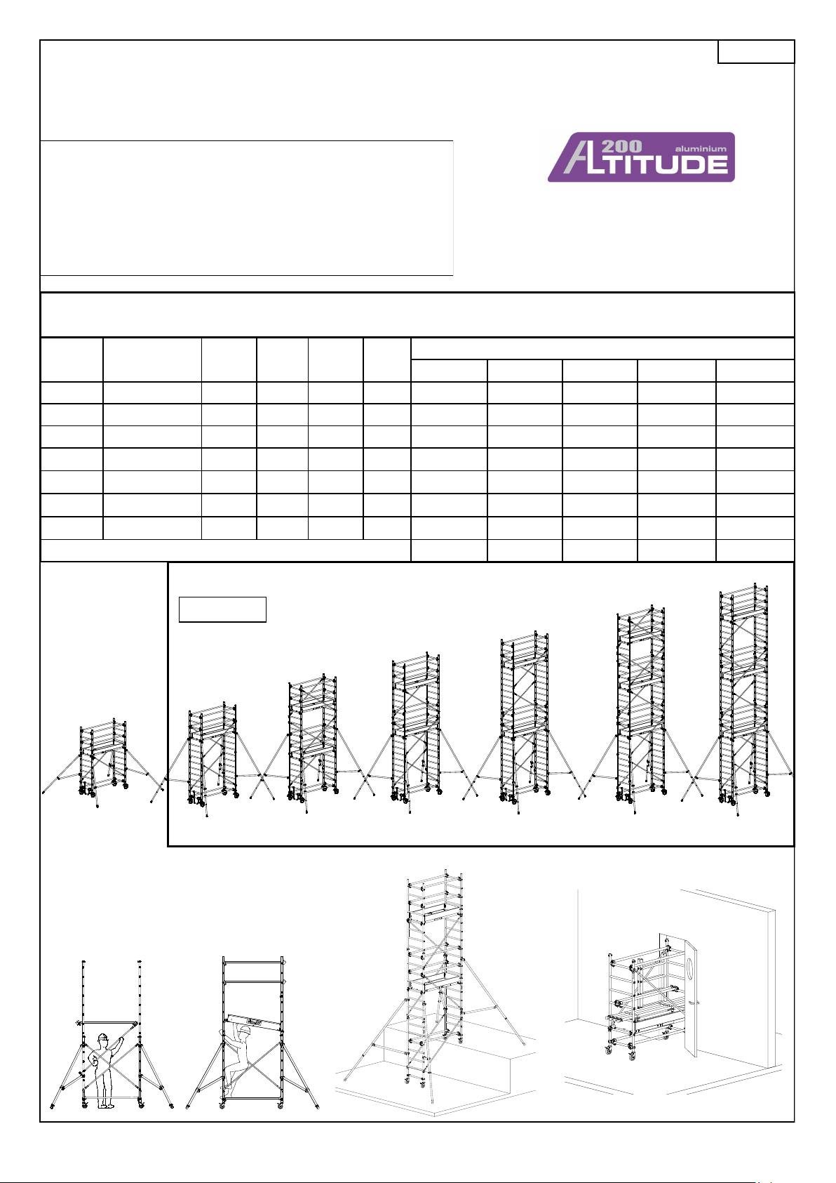
ASSEMBLY, DISASSEMBLY AND USE INSTRUCTIONS
Compliant with norm NF EN 1004
Compliant with Decree dating form 01/09/04
LOADING CONDITIONS
Floor: Maximum allowed load spread over the floor = 205 kg
Whole scaffolding: Maximum allowed load spread over the
floors = 500 kg
ALTITUDE 200
D040369B
Code
Gencod
500812 1.9 m 3.9 m Class 3 71 Kg 1 1 376016602065 2
500813 2.9 m 4.9 m Class 3 78 Kg 1 1 1 376016602066 9
500814 3.9 m 5.9 m Class 3 108 Kg 1 2 1 376016602067 6
500815 4.9 m 6.9 m Class 3 113 Kg 1 2 1 376016602068 3
500816 5.9 m 7.9 m Class 3 119 Kg 1 2 1 1 376016602069 0
500817 6.9 m 8.9 m Class 3 150 Kg 1 3 1 1 376016602070 6
500818 7.9 m 9.9 m Class 3 154 Kg 1 3 2 376016602071 3
(class 3 = 200 Kg/m² spread load)
NF EN 1004
500812
Floor
height
500813
Work
height
Load Weight
500814
Parcel
500011 500016 500013 500014 500015
376016602016 4 376016602059 1 376016602018 8 376016602019 5 376016602020 1 Gencod
500818
500817
500816
500815
1.9 m floor
height
Safe assembly
2.9 m floor
height
3.9 m floor
height
Assembly on a difference
in height
4.9 m floor
height
5.9 m floor
height
6.9 m floor
height
Fitting through doors
7.9 m floor
height
Page 5/20
Page 6
D040369B
C257104
C257104
C257105
C257105
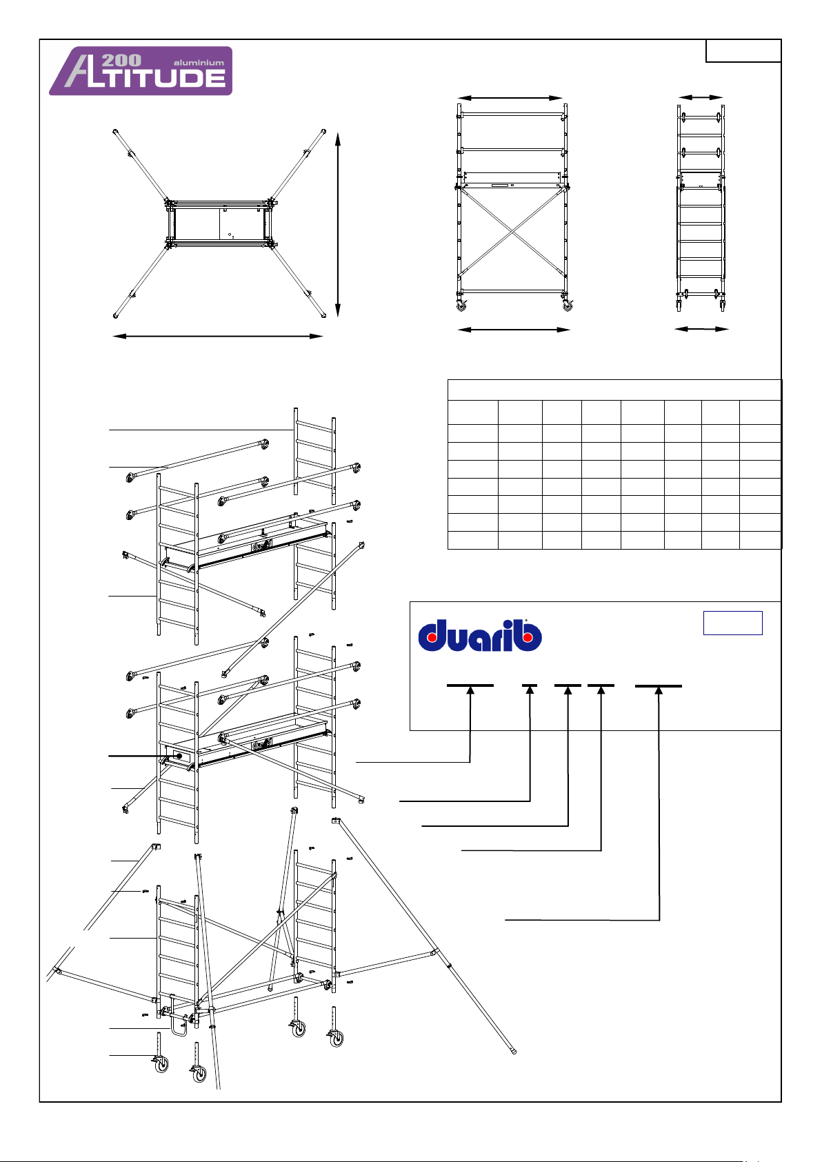
Min dim. A
Center-to-center D
Min dim. B
Overall C
Center-to-center E
Overall F
Dimensions
Code
500816 5.9 m 3580 3260 2100 2000 690 790
500817 6.9 m 3560 3680 2100 2000 690 790
500818 7.9 m 4060 4220 2100 2000 690 790
Floor
height
1.9 m 2240 1480 2100 2000 690 790 500812
2.9 m 2740 2040 2100 2000 690 790 500813
3.9 m 2800 2200 2100 2000 690 790 500814
4.9 m 3220 2680 2100 2000 690 790 500815
A B C D E F
Unit of measurement: mm
C257103
C257103
11308
11308
C257108
C257108
C257009
C257010
C257112
EN1004 - 3 – 7,9/7,9 - XXXD Rolling
Reference to the norm
Load evenly spread class
(class 3, 200 Kg/m²)
Maximum outdoor height use
Head Office:
Route de la Limouzinière
44310 St Philbert de Grand Lieu
Follow the assembly and use instructions
Maximum indoor height use
Access via stairs: no
Access via step stairs: no
Access via tilted ladder: no
Access via vertical ladder: yes
08068
C257109
C257101
Page 6/20
Page 7
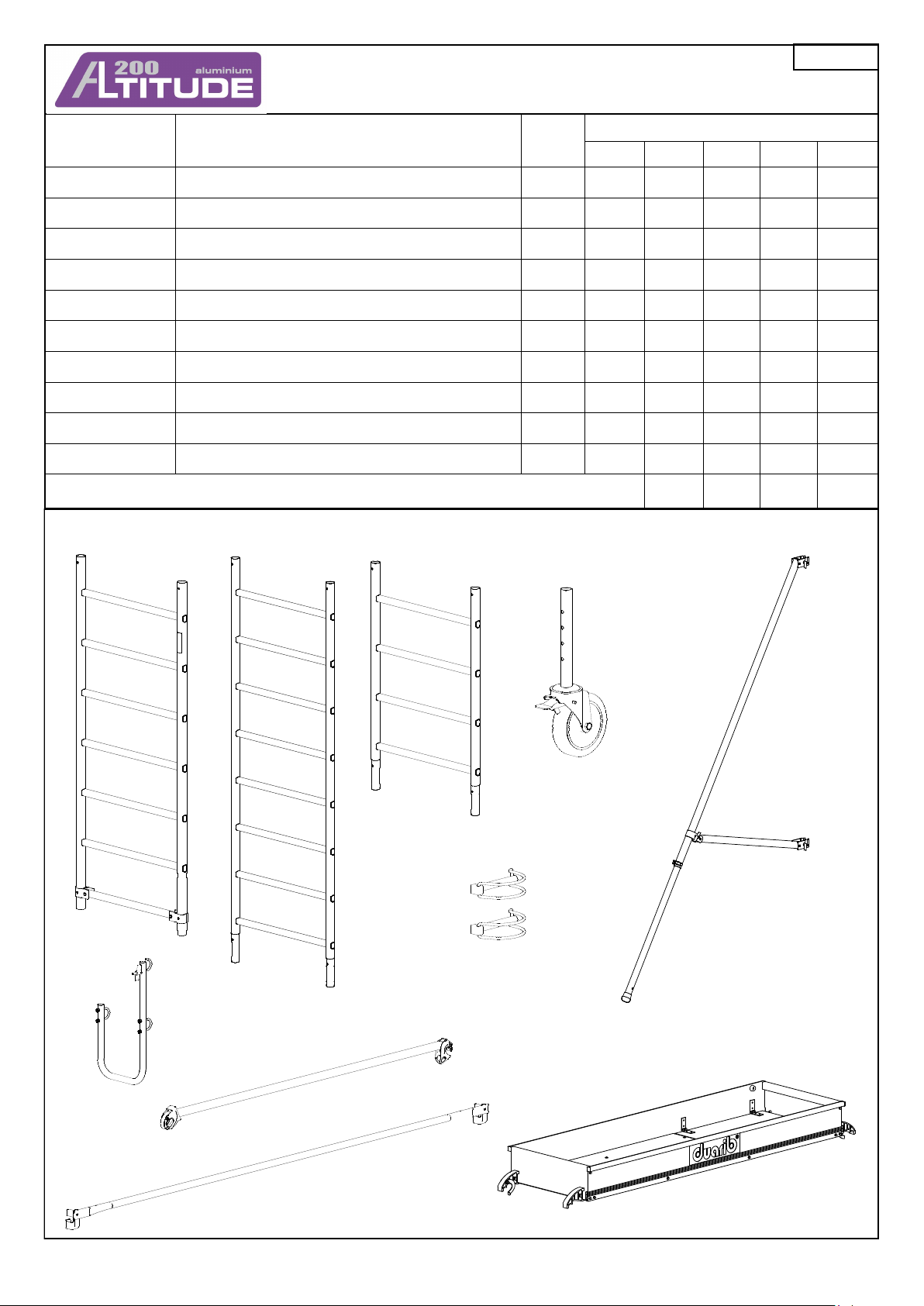
PARCEL CONTENT
D040369B
Code Description
C257101
C257112
C257109
C257103
C257104
C257105
11308
C257108
C257009
C257010
C257112
Ø200 wheel adjustment on 15 cm. 3.3
1.765m x 0.69m base ladder 4.7
1st step with screw and bolts 0.9
2m x 0.69m ladder 4.7
1m x 0.69m ladder 2.4
2 m handrail 1.4
2m wide alu-wood floor with integrated toeboards 17.4
Brace's Lg: 2.4m 1
Stabilizer's Lg: 2.476m 3.7
Pin (bundle w/ 2 pins) 0.05
C257103
Weight
Kg
Parcel weight
C257104 C257101
Parcel
500011 500012 500013 500014 500015
4
2
1
1 2 3
2
2 4
1
2 2 4 4
4
4 1 2 3
48.3 Kg 23 Kg 6.8 Kg 13.6 Kg 18.4 Kg
C257109
C257009
C257010
C257105
C257108
11308
Page 7/20
Page 8
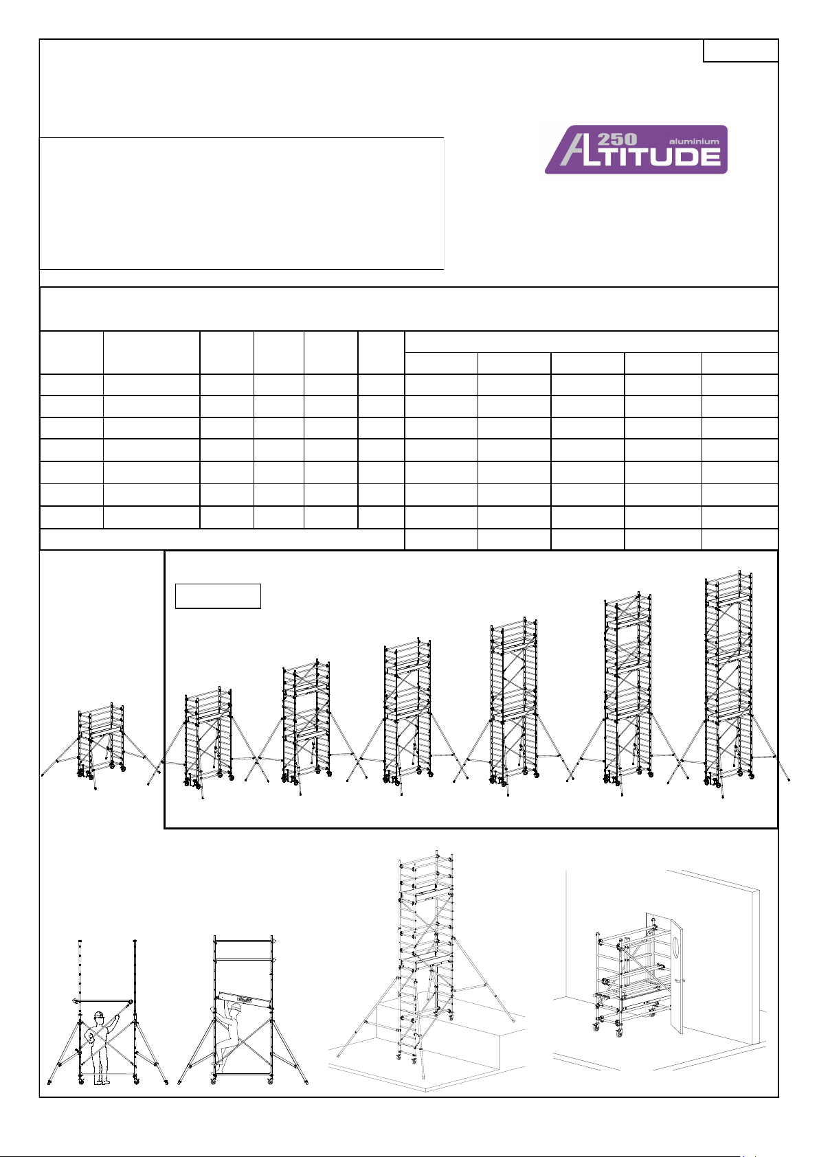
ASSEMBLY, DISASSEMBLY AND USE INSTRUCTIONS
Compliant with norm NF EN 1004
Compliant with Decree dating form 01/09/04
LOADING CONDITIONS
Floor: Maximum allowed load spread over the floor = 260 kg
Whole scaffolding: Maximum allowed load spread over the
floors = 500 kg
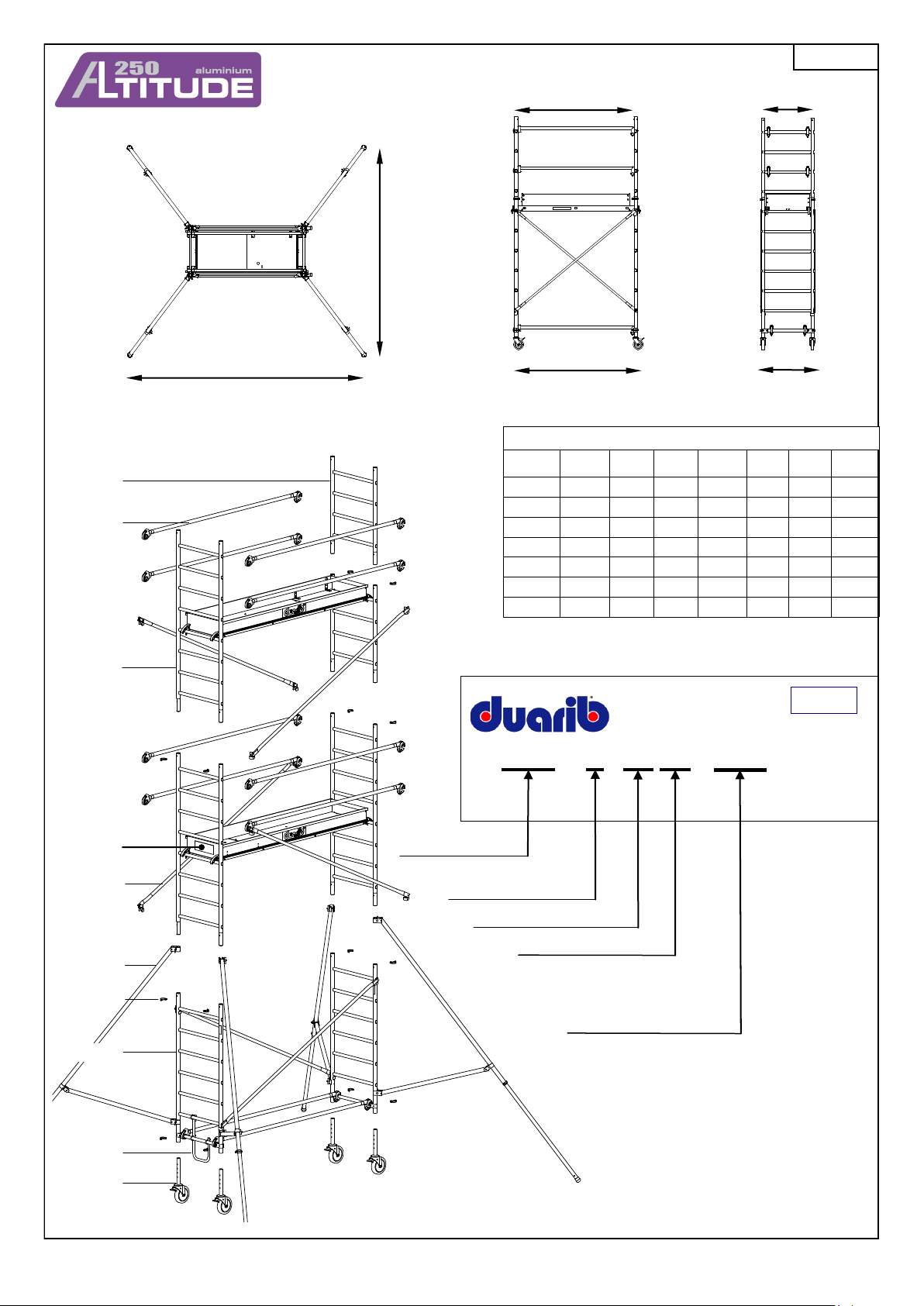
ALTITUDE 250
D040369B
Code
Gencod
500822 1.9 m 3.9 m Class 3 78 Kg 1 1 376016602072 0
500823 2.9 m 4.9 m Class 3 86 Kg 1 1 1 376016602073 7
500824 3.9 m 5.9 m Class 3 122 Kg 1 2 1 376016602074 4
500825 4.9 m 6.9 m Class 3 127 Kg 1 2 1 376016602075 1
500826 5.9 m 7.9 m Class 3 134 Kg 1 2 1 1 376016602076 8
500827 6.9 m 8.9 m Class 3 170 Kg 1 3 1 1 376016602077 5
500828 7.9 m 9.9 m Class 3 175 Kg 1 3 2 376016602078 2
(class 3 = 200 Kg/m² spread load)
NF EN 1004
500822
Floor
height
500823
Work
height
500824
Load Weight
500825
Parcel
500021 500026 500023 500024 500025
376016602021 8 376016602060 7 376016602023 2 376016602024 9 376016602025 6 Gencod
500828
500827
500826
1.9 m floor
height
Safe assembly
2.9 m floor
height
3.9 m floor
height
Assembly on a
difference in height
4.9 m floor
height
5.9 m floor
height
6.9 m floor
height
Fitting through doors
7.9 m floor
height
Page 8/20
Page 9
D040369B
Center-to-center D Center-to-center E
Min dim. B
C257104
C257205
C257103
Min dim. A
Overall C
Overall F
Dimensions
Code
500826 5.9 m 3460 3420 2100 2000 690 790
500827 6.9 m 3400 3840 2100 2000 690 790
500828 7.9 m 3860 4400 2100 2000 690 790
Floor
height
1.9 m 2360 1400 2100 2000 690 790 500822
2.9 m 2820 2020 2100 2000 690 790 500823
3.9 m 2740 2240 2100 2000 690 790 500824
4.9 m 3140 2800 2100 2000 690 790 500825
A B C D E F
Unit of measurement: mm
Head Office:
Route de la Limouzinière
44310 St Philbert de Grand Lieu
08068
EN1004 - 3 – 7,9/7,9 - XXXD Rolling
Follow the assembly and use instructions
11309
Reference to the norm
Load evenly spread class
C257208
(class 3, 200 Kg/m²)
Maximum outdoor height use
Maximum indoor height use
C257009
Access via stairs: no
Access via step stairs: no
C257010
Access via tilted ladder: no
Access via vertical ladder: yes
C257112
C257109
C257101
Page 9/20
Page 10
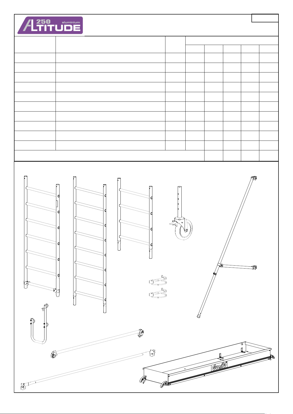
PARCEL CONTENT
D040369B
Code Description
C257101
C257112
C257109
C257103
C257104
C257205
11309
C257208
C257009
2.5m wide alu-wood floor with integrated toeboards 20.4
Ø200 wheel adjustment on 15 cm 3.3
1.765m x 0.69m base ladder 4.7
1st step with screw and bolts 0.9
2m x 0.69m ladder 4.7
1m x 0.69m ladder 2.4
2.5 m handrail 1.9
Brace’s Lg: 2.8m 1.5
Stabilizer’s Lg: 2.476m 3.7
C257010 Pin (bundle w/ 2 pins)
C257112
C257103
C257104 C257101
Weight
Kg
0.05
Parcel weight
Parcel
500021 500026 500023 500024 500025
4
2
1
1 2 3
2
2 4
1
2 2 4 4
4
4 1 2 3
50.3 Kg 28 Kg 7.8 Kg 15.6 Kg 20.4 Kg
C257109
C257009
C257010
C257205
C257208
11309
Page 10/20
Page 11
DUARIB
PATENT
D040369B
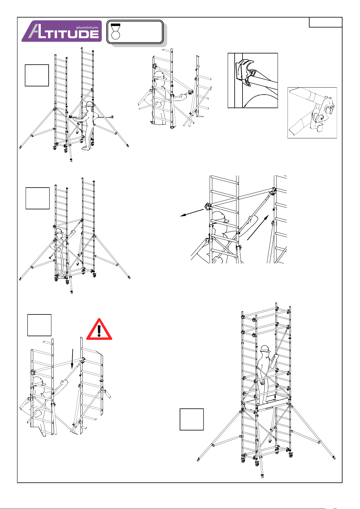
Handrail safe assembly
1
2
Diag. 2
Diag. 1
Set the handrail with the hook, as indicated on diagram 1,
by leaving the lock open.
Using the brace's end, joint it in the other end of the handrail, as indicated on
diagram 2
3
Set the handrail with the brace, first by moving the handrail back
then by moving up and joint in the other end.
With the brace, close the lock at
the end of the handrail on the
rung with a small movement
downwards.
You will close the second lock of
the handrail when access to the
upper level is possible.
4
Repeat this step to safely set the
upper level handrails.
Page 11/20
Page 12
DUARIB
PATENT
D040369B
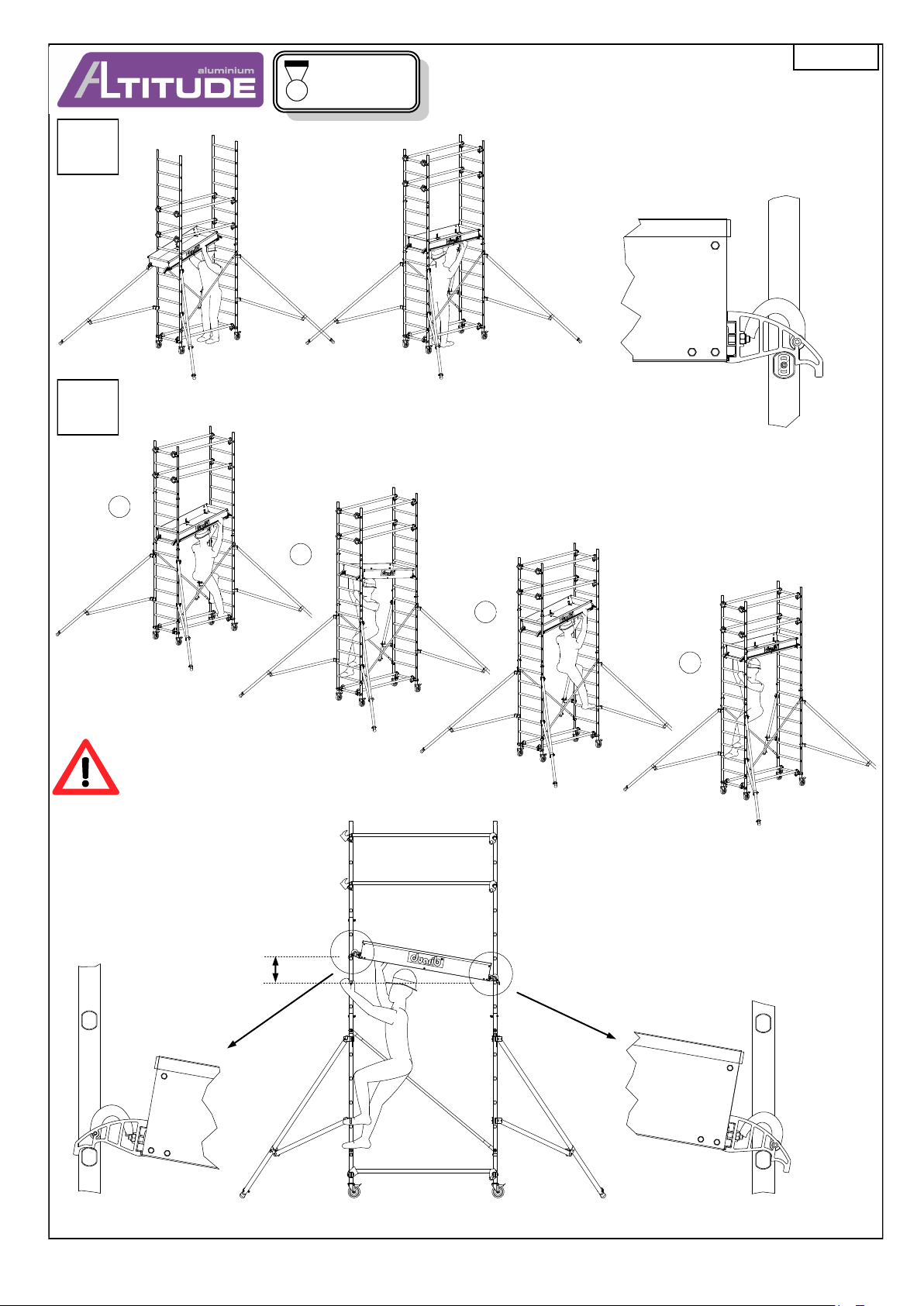
Floor safe assembly
1
2
Set a floor about six feet off the
ground, leaving the floor's locks
open.
Setting the floor at a higher position is done by moving each end
of the floor one after the other until you have reached the desired
1
2
height.
The distance between each floor
cannot exceed 3m.
1 rung maximum
3
4
The floor's hooks allow for a difference of
one rung maximum.
Page 12/20
Page 13
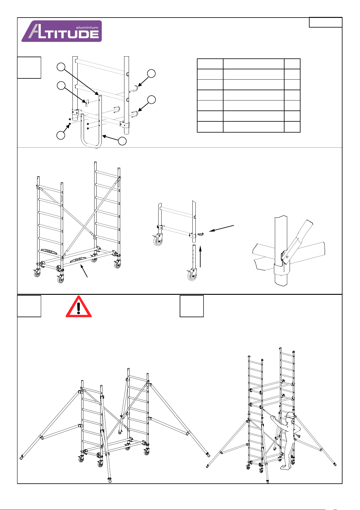
The first bent step must be set only on one of the two base ladders for the
Altitude 200 and 250 scaffoldings. This step must be set inside the scaffolding.
D040369B
1
2
3
4
5
6
1
Attach and pin the wheels on the base ladder.
Set two handrails on the first rung.
Set up the braces and lock them.
Activate the wheels' brake.
With a spirit level, check the handrails and the rungs are horizontal.
Mark Description Qty
1 Ø25 bent pipe 1
2 Plastic pipe cap 2
3 Open stirrup 1
4 M8 wing-nut connector 1
5 "U" shaped stirrup 2
6
H M8 brake nut
Brace's lock position:
4
closed.
Spirit level
2
Set the stabilizers.
Fine-tune the stabilizers so they touch the
ground. Be careful, the wheels must stay in
contact with the ground.
3
Set two 2m ladders
Pin both ladders.
Set up 4 handrails from the ground by following the safe
handrail assembly instructions.
Page 13/20
Page 14
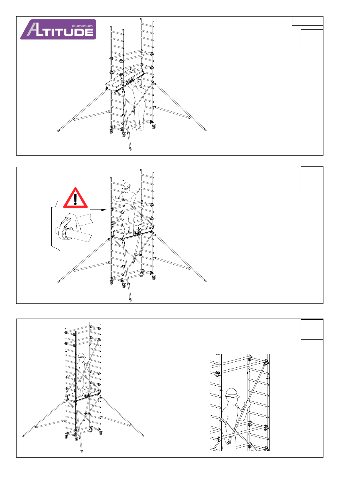
Set the first floor up.
Close the two locks at each end of the floor's hooks.
Go up on the floor
Close the locks of all four handrails
Set and lock two braces
D040369B
4
5
Set two 1m ladders
Pin both ladders
With the help of a brace, set four handrails for the upper level by following the
handrail's safe assembly instructions
6
Page 14/20
Page 15
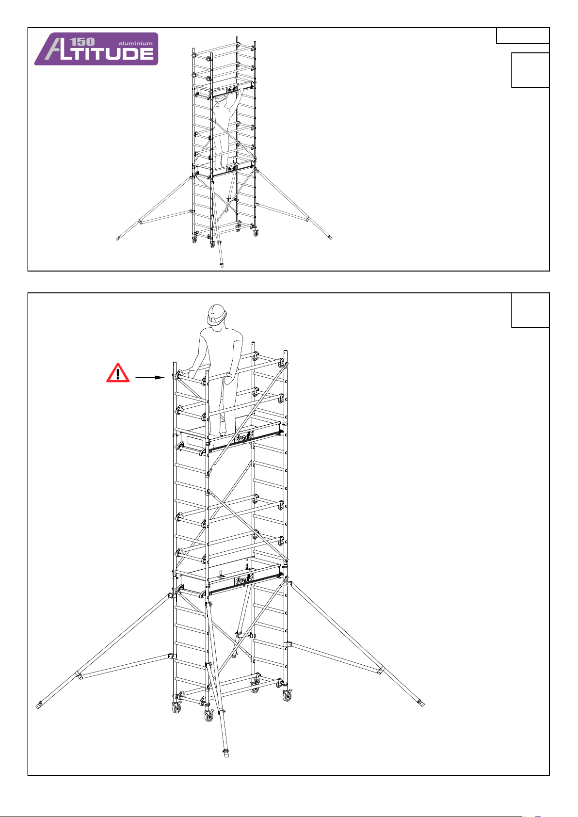
Set the floor for the upper level
Lock the floor
D040369B
7
8
Go up on the floor
Close the locks of all four handrails
Set both handrails
Page 15/20
Page 16
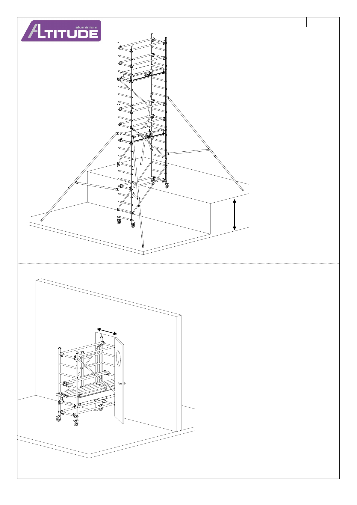
Assembly on a difference in height
D040369B
1m max
Assembly for transport and to fit through doors
Door width
The Altitude 150 scaffolding can fit through a 0.7m (width) x
1.93 (height) door.
The Altitude 200 and 250 scaffoldings can fit through a 0.8m
(width) x 1.93 (height) door.
In this setup, you can transport your hardware and small
tools.
Page 16/20
Page 17
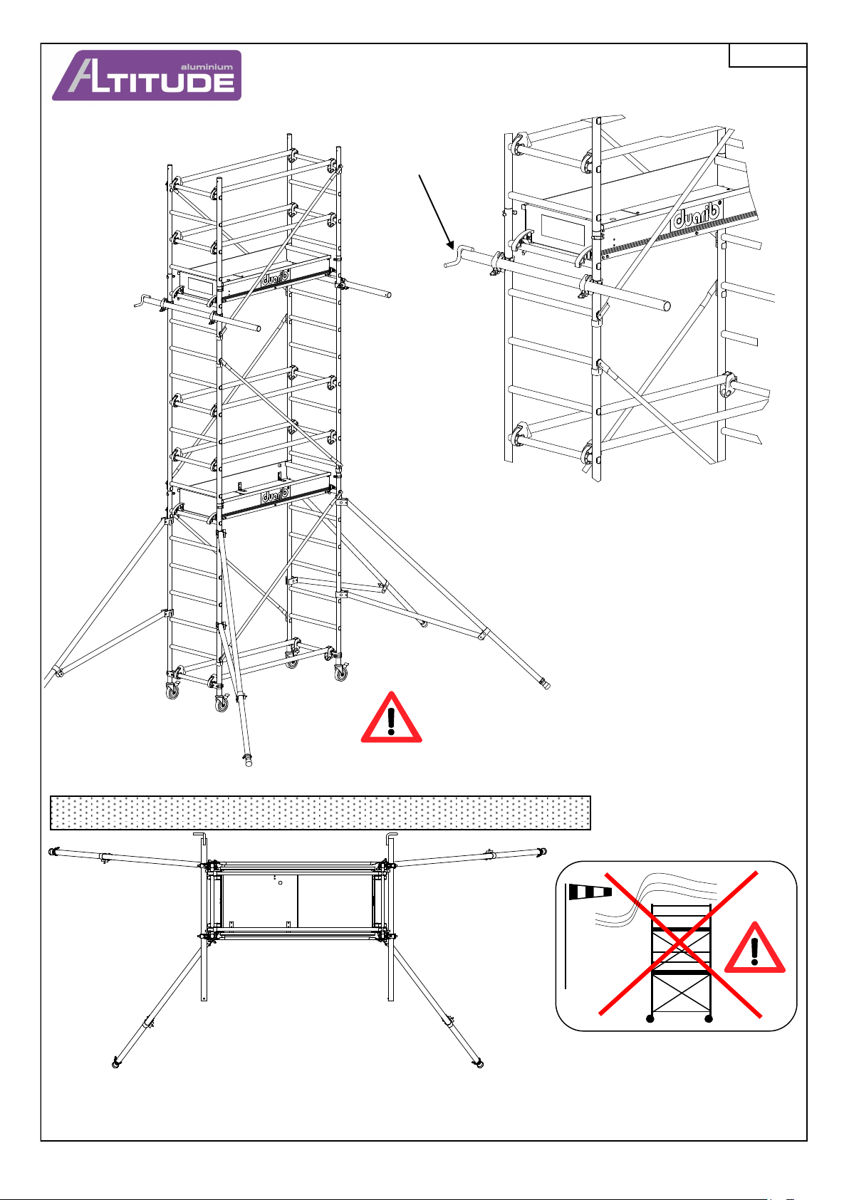
Special case: Anchors assembly
Anchor
D040369B
With a wind speed superior to 45 kmph, it is mandatory to
either disassemble or anchor it at the top.
If you chose to anchor it:
Set the stabilizers according to the below picture
Add 2 anchors at the top.
Anchors not included in the parcel (Anchoring kit code:
20865)
If the wind exceeds 45 kmph, it is forbidden to use the
scaffolding, even if it is anchored.
Top view
Superior to
45 kmph
Use the scaffolding when the wind doesn't
exceed 45 kmph.
If the wind exceeds 45 kmph, anchor the
scaffolding at the top or disassemble it.
Page 17/20
Page 18
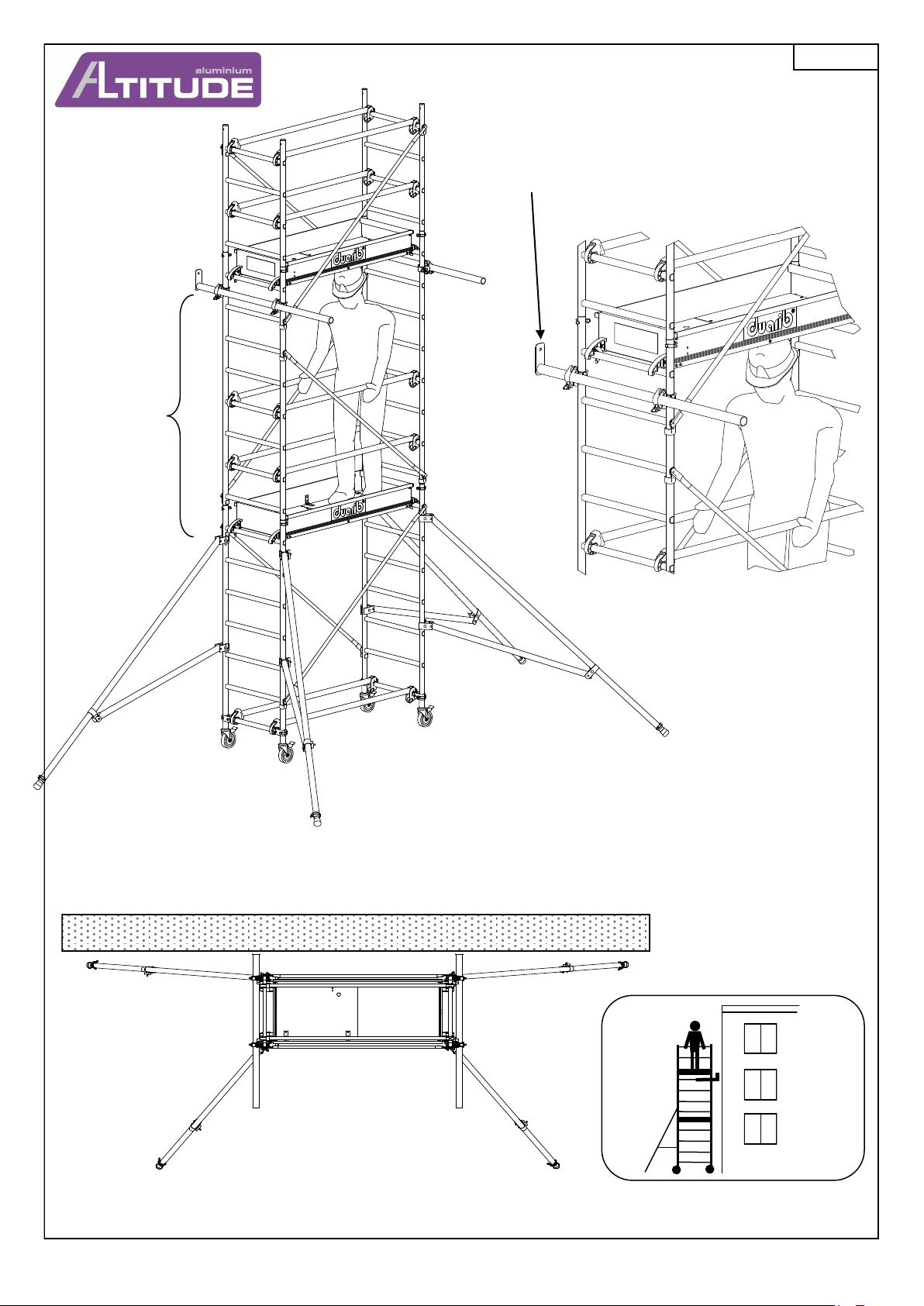
Special case: Supporting bar assembly
Supporting bar
Supporting bar set up zone
D040369B
Here are some ways to guarantee the scaffolding's stability when
mounted in front of a building:
Set the stabilizers according to the below picture
Add 2 support bars on the upper end (one on each vertical upright)
Supporting bars not included in the parcels
Supporting bars must always be set above the stabilizer's upper
attachment point.
OK
When working on the front of the building,
use stabilizers and add 2 support bars.
Page 18/20
Page 19
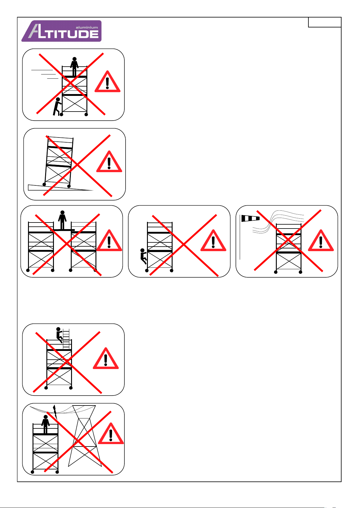
Safety measures
D040369B
It is forbidden to move a scaffolding that has a rolling bridge, a crane or handling equipment.
the moving area must be free of obstacles.
The scaffolding can only be manually moved on solid ground (for a loose ground, plan a roll
out walkway), free of personnel or tools, with the space between supporting bars and the
ground being very low.
Do not move the scaffolding if the wind speed exceeds 45 kmph.
All 4 wheels must always touch the ground in order to support the work load and the
structure's own weight. Maximum load on one wheel: 125 kg.
Make sure that support points can bear the load on the ground and that contact surface is
properly calculated according to the ground's type (on loose ground, use wedges under the
wheels and the supports, do not use hollow breeze blocks or any other non reliable wedges).
Assemble the scaffolding on a flat ground that is on a level.
It is forbidden to use a scaffolding that has not been vertically assembled (1% tolerance).
It is forbidden to jump on floors.
It is forbidden to create a bridge between a
rolling scaffolding and a building or any
other fixed structure.
It is forbidden to use planks as a floor.
Superior to
45 kmph
Only go up or down the scaffolding
through the trapdoors in the floors.
Use the scaffolding when the wind doesn't
exceed 45 kmph.
The scaffolding must be secured at the
end of the day, by anchoring it or
disassembling it.
Beware of turbulences when near the
angle of a building or under a porch.
It is strictly forbidden to extend the height over the one mentioned in this user guide.
It is forbidden to set up a ladder or any other accessory on the floor to extend the scaffolding.
Make sure the work area is far from any working power line.
Page 19/20
Page 20
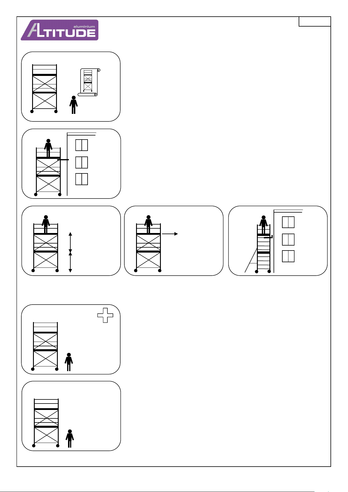
OK
OK
Safety measures
Assembly and disassembly must be performed by operators who have been trained in
assembly and security instructions.
Only use parts in good condition we have manufactured and referenced in the nomenclature.
Make sure the assembly is compliant with the user guide.
For any use not compliant to the user guide, please contact the manufacturer.
Before going on the scaffolding, please check that stabilizers are tightened and wheels locked.
Check that all the parts are pinned and that security features are locked.
During assembly and disassembly, you must wear Personal Protective Equipment, such as:
hard hat, safety shoes, gloves…
Respect the assembly order described in this user guide to the letter.
Anchor the scaffolding to a building or any other surface that can bear the stress.
Anchor the scaffolding on the top part at the end of each operation.
D040369B
3m max 3m max
According to the current regulation, the
space between two floors cannot exceed
3m.
OK
OK
Maximum force: 30kg
OK
Horizontal forces must not exceed 30 kg
on the last floor level.
MAINTENANCE:
Before any assembly or use, you must check all the parts of the scaffolding to see if any could be
defective and replace it, if necessary.
You must make sure that:
Wheel treads and their brakes work properly.
All lock mechanisms (base body, handrails, diagonal braces) work properly.
The plywood of the floor and the trapdoor are in good condition.
DISASSEMBLY:
Before any disassembly, check that the wheels are locked and stabilizers are firmly tightened.
For the disassembly, respect the reverse assembly order described in this user guide to the
letter.
Disassemble them gradually to operate with maximum security.
When working on the front of the building,
use stabilizers and add 2 support bars.
OK
OK
Page 20/20
 Loading...