

Page 1
System programming and SMS remote controlling the TS100
The TS100 understands the same commands via SMS as from a PC with the only difference that in an SMS message the
”dt+” part of the commands are not included and for the command ”dt+ipassw” the complete command is left out and
only the actual password included in the message. The password must always be located first in the SMS message. SMS
programming is done by creating an SMS message in a standard cellular phone and sending it to the phone number of the
SIM card that´s placed in the TS100. Several commands may be included in the same message and are then separated by
comma signs.
NOTE 1: Programming via SMS requires that the TS100 is not in PC programming mode. The PC programming cable
may be connected to the unit and the TS100 will in this case also display a message once receiving an SMS but the
programming mode must be left with the command “exit” before the TS100 will recognize any incoming SMS messages.
NOTE 2: Messages must be started with an exclamation mark and ended with two exclamation marks:
!password, command1,command2,command3!!
and can be maximum 160 characters long.
NOTE 3: The command ”exit” is not used via SMS. The TS100 will automatically leave programming mode once all
SMS commands are executed.
NOTE 4: All system parameters are stored on a non-volatile memory area meaning that all parameters will be unchanged
also after a possible power loss with the exception of the system time (used only if the unit is programmed to deliver test
messages at certain times). This means that if you want to PC-program the TS100 prior to the actual installation occasion,
this is best solved by that all parameters are entered except the system time which may then be entered after the installation
using an SMS message.
Examples of SMS messages to program and/or remote control the TS100:
Ex 1
!admin, rec1=123456789,msg3=Input 1,msg3rec=1,msg3s!!
Receiver 1 is set up to 123456789, msg3 (the message delivered at activation of input 1) is set to ”Input 1”, msg3rec=1
means that the at activation, message 3 is to be delivered to receiver one only and “msg3s” activates a simulation of msg3
(activation of input 1) meaning that the TS100 will immediately deliver “Input 1” to receiver no 123456789.
Ex 2
!admin,setpassw=asdfg,rec1=1234,rec2=5678,msg3=Input 1,msg4=Input 2,msg3rec=1,msg4rec=12,dt+swtime=1!!
Password is changed to asdfg, receiver 1 is set to 1234, receiver 2 is set to 5678, mottagare 2 sätts till 5678, msg3 (the
message delivered at activation of input 1) is set to ”Input 1”, msg4 (the message delivered at activation of input 2) is set to
”Input 2”, message 3 is delivered to receiver 1 only, message 4 is delivered to both receiver 1 and receiver 2 and the delay
time for switching LINE OUT from PSTN to GSM at a line failure is set to 1 (approximately 30 seconds).
Ex 3
!admin,setpassw=pwdpw,rec1=123456789,out1=1,out2=0,time=080528113000,listsms!!
Password is changed to pwdpw, receiver 1 is set to 123456789, output one is closed to GND (supply -), output 2 is
released from GND (supply -) if it was previously activated, the system time is updated to 2008-05-28, 11:30:00 and the
TS100 is finally ordered to deliver system settings to receiver no 1. The TS100 will reply with an SMS message to receiver
number one:
”ipassw,msg3**,swtime,msg1rec,msg2rec,msg3rec,msg4rec,msg5rec,msg6rec,rsttxt,testtime1,testime2,testtime3,out1,
out2,rec1,rec2,rec3,rec4,”
Positions where nothing is programmed will be displayed with a simple minus sign in the message, ex:
”pwdpwd,0,0, 1, 1, 1, 1, 1, 1, reset, 2400, 2400, 2400, 1, 0, 123456789, - , - , - ,”
Ex 4
!admin,out1=1,out2=1!!
Activate (close to GND) outputs one and two.
Ex 5
!admin,out1=0,out2=0!!
Deactivate (release from GND) outputs one and two.
Dualtech TS100T – System Description and Installation manual
System description
Normally, the TS100 is installed as the first client on the wired telephone line (PSTN). The alarm dialer will get access to the
PSTN line from the TS100 output “LINE OUT”. The TS100 constantly supervises the PSTN line and at a line failure, the “LINE
OUT” socket is switched to a simulated telephone line generated onboard the TS100. After the delay time set with DIP 2, the
error output “PSTN ERR” will be activated and if connected to a section of the alarm panel also cause the alarm panel to make a
call and deliver the line error alert to the receiving centre. The call is automatically done using the GSM voice channel and to the
alarm panel, the TS100 in this mode operates exactly as a PSTN socket. Further alarm messages are also distributed by the
TS100 over the GSM channel and as soon as a PSTN line restoral is detected, the “LINE OUT” socket is immediately switched
back to the PSTN landline.
Installation (NOTE: If no SMS or remote control features are to be used, page 2-4 of this manual may be ignored.
1. Connect incoming PSTN line (if available) to socket ”LINE IN”. If no connection, the TS100 will operate in GSM mode.
2. Connect the alarm panel line input to socket “LINE OUT”
3. Connect the TS100 error outputs E1 E1 (activated at removal of the cabinet lid), E2 E2 (activated at GSM error) and E3 E3
(activated at a PSTN error) to alarm sections on the alarm panel.
4. Enter a SIM card into the TS100 SIM card reader. NOTE: The card may not be protected by a PIN code. Use a standard
cellular phone to switch the PIN code protection off.
5. TS100 will boot once supply voltage 10-30 VDC is connected to socket SUPPLY. During a boot period, green LED 1 is
flashing once per second (searching for GSM network) and the other LED´s keeps flashing once per second. The unit will enter
idle mode once GSM network is located and logged on to.
6. Locate a suitable antenna placement by setting DIP6 to ON position. This will make the green LED 2 and the red LED
together indicate the GSM network signal strength. Both LED´s should be lit for proper operation. Normally, the antenna may be
placed on top of the TS100 cabinet.
7. Test the system by removing the PSTN line from the LINE IN socket. LINE OUT will immediately switch to GSM and
after the delay time set with DIP 1, the error output E3 E3 is activated, an alarm is triggered on the alarm panel and the PSTN
ERROR alert is delivered to the receiving centre via the GSM network.
Important notes
The TS100 must be located first on the incomnig telephone line. If not, lifting hook on other equipment (i.e. phone or fax)
located prior to the TS100 in the same telphone network will result in a line failure on the TS100.
Verify that the SIM card is not PIN code protected. Use a standard cellular phone to switch the PIN code protection off.
If the TS100 error outputs are used the alarm panel must be programmed with additional characters for the TS100 specific
error outputs.
The alarm dialler must be programmed to always dial area code prior to the receiver number. This has no effect via the
landline but is a must when using the GSM network.
If the TS100 is connected via a switchboard, verify that an external line failure is also detectable on the TS100 LINE IN.
TS100 technical data
Supply voltage: 10-30 VDC.
Current consumption standby, appr: 120 mA.
At GSM transfer, appr: 200 mA.
EN
DIP switches
1, Delay time PSTN ERROR (sec)
OFF: 30, ON: 240
2, Delay time GSM ERROR (sec)
OFF: 1200, ON: 300
3, PSTN tone detection on/off
OFF: on, ON: off
4, Error outputs NC (closing to GND (= supply -)) or
NO (breaking from GND (= supply -))
OFF: NC, ON: NO
5, Switchboard setting
OFF: No switchboard, ON: TS100 will ignore the first
digit dialled by the alarm dialler
6, LED indication (green LED2 + red LED)
OFF: Normal, ON: GSM signal strength
5&6, Enhanced switchboard setting
If both DIP 5 and 6 are set to position ON, the first two
digits in the number dialed by the alarm dialer are ignored.
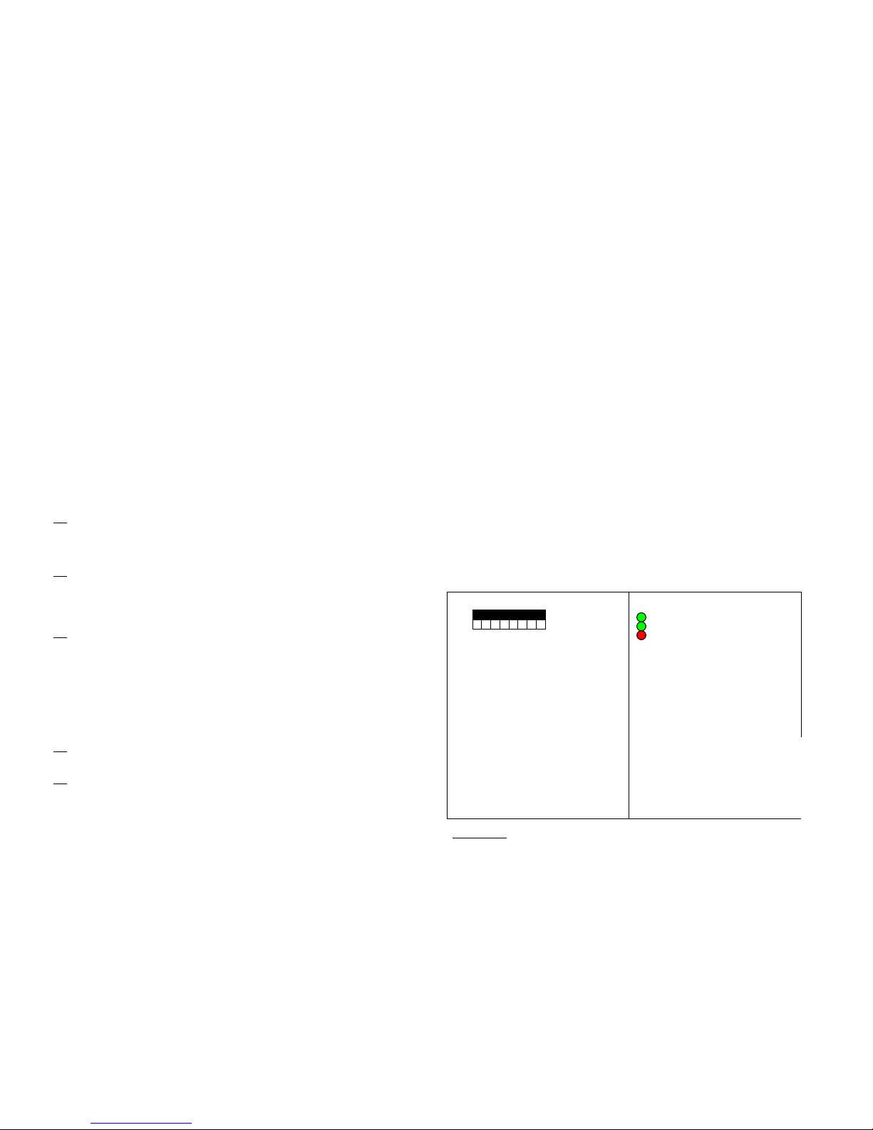
LED´s
Grön diod 1
Grön diod 2
Röd diod
Green LED 1
Off: GSM module off
Flashing once/sec: Searching for GSM net
Flashing once every third sec: Logged on to GSM net
Green LED 2
Lit: “LINE OUT” in GSM mode
Off: “LINE OUT” in PSTN mode
Red LED
Lit: “GSM ERROR” activated. Check SIM card and
antenna
Green LED 2 and red LED ”rolling” indicates
ongoing GSM call or SMS transfer
1 2 3 4 5
LED´s
ON
OFF
Installts100tt-bga_EN_r11.doc
Date: 2008-06-16
System processor: M164P, SW rev 2.1 and forward
Green LED 1
Green LED 2
Red
LED
Page 2
The TS100 has four alarm inputs (I1-I4) for SMS alarm messaging to up to four different receivers numbers. An alarm
transfer is initiated by closing the input to system GND (supply minus). Each of the inputs may be coupled to anyone of
the four receivers. The TS100 is programmed from a PC or via SMS using so called dt commands. dt commands via SMS
is also used for remote control of the two outputs O1 and O2. A dt command from a PC is always started with dt+ followed
by the actual command. The only exception is the command exit which is entered as just “exit”. At programming and
remote control via SMS, the dt+ is left out to minimize the message size. The command “exit” is not used via SMS but the
TS100 will in this case automatically leave programming mode once all SMS commands have been executed.
Command Explanation
ipassw State system programming password. Must be 5 characters. Default: admin
setpassw Enter new system programming password. Must be 5 characters.
recx Enter receivers where x=1-4. Max 16 digits per receiver phone number.
msgx Enter alarm texts where x=1-6. Max 31 characters per message.
Msg1: Delivered at activation of programmed test time (if programmed). Default: Test
Msg2: Delivered at PSTN Error. Default: PSTN Error
Msg3-Msg6: Delivered at activation of inputs 1-4. Default: In1 – In4
msgxrec Connect message to receiver(s) where x=1-4. Default: All messages to receiver one only.
rsttxt Enter text to include in alarm message once the alarm is reset. If no text is entered there will be
no reset message delivered. Default: Reset.
msgxs Simulate alarm activation where x=1-6.
time Set system time. Format: yymmddhhmmss, ex: dt+time=080522103000
testtimex Set time for test alarm activation where x=1-3. Once the system clock reaches the test time
programmed, the TS100 will switch to GSM mode and activate (close to system GND) output
O2 for one minute. If O2 is connected to an alarm panel section, this is a way to apart from an
SMS also test the GSM channel up to three times per day.
list List all system settings. Used at PC programming. All system settings are listed on the screen in
the format:
”ipassw,msg3=**,swtime,msg1rec,msg2rec,msg3rec,msg4rec,msg5rec,msg6rec,rsttxt,testtime1,t
estime2,testtime3,out1,out2,rec1,rec2,rec3,rec4,msg1,msg2,msg3,msg4,msg5,msg6”
listsms Equal to list, but in this case all settings except the text messages are delivered as an SMS to
receiver number one (rec1).
dt+msg3=**0, 1 or ? 0: Input one operates as an alarm input (default).
1: Input one is used to force the TS100 into GSM mode regardless of the PSTN status
Ex: dt+msg3=**0 or dt+msg3=**1
?: Show status. Ex, question: dt+msg3=**? Reply: 0 or 1 followed by OK
dt+swtime=0,1 el 2 Set delay time from the actual loss of PSTN line to the point where TS100 switches LINE OUT
to GSM mode where 0=2 sec, 1=30 sec and 2=60 sec. Ex: dt+swtime=0. Default: 0
System programming from a PC
The TS100 is programmed from a PC using the TS100TtBGA programming cable that provides a bridge from an USB
port on the PC to serial TTL level communication on the TS100 side. The cable may be used from any serial
communication software, ex the Windows HyperTerminal or the free software Teraterm that is available on the Dualtech
web site.
Installing the TeraTerm
TeraTerm is available as a zip-file on www.dualtech.se/downloads under TS100/Software/TeraTerm. Log in to the site
using user: downloads and password: x3GGvpvZuU. Download and unzip the file ”ttermp23”. Open the file
TERATERM.INI located in the same folder, change the parameter MaxComPort from 4 to 8, save the file again and
double click on install.exe to install TeraTerm with support for up to 8 COM ports on the PC. At the installation, enter the
path: C:\PROGRAM\TTERMPRO to install to.
Installing the programming cable
Download the cable drivers from www.dualtech.se/downloads under TS100/Pgmcable/Drivers. Log in to the site using
user: downloads and password: x3GGvpvZuU. Download and unzip the file ”CDM 2.04.06 WHQL Certified” in optional
folder on the PC.
1. Connect the programming cable to a PC USB port. The cable will be installed by Windows in two steps: first
the actual cable and the a virtual COM port that can then be used by the TeraTerm software.
2. Windows will state ”found new hardware” and suggest that drivers are installed. On the question if Windows
is allowed to search the Internet for drivers, answer no nad direct Windows to the folder where the unzipped
drivers are located.
3. After installing the cable drivers, Windows will once again state ”found new hardware” (the virtual COM
port). Direct to the same folder again and wait until the Windows has finished installing the COM port
drivers.
4. Launch the PC Control Panel and double click ”System”. Choose hardware and launch the Device
Manager.Double click on “Ports (COM&LPT)”. You should find a USB Serial Port with a port number (ex
COM4). This port number will be entered in TeraTerm when connecting to the TS100.
5. Launch the TeraTerm software using ”Start/Program/TeraTerm” or similar. Check ”Serial” and state the port number given for
the USB Serial port according to description on the previous page (ex COM4). In the TeraTerm, click Setup-Terminal and check
”Local Echo” followed by OK. Clisk Setup-Terminal and verify the settings to be correct port number for the programming
cable, Baud Rate = 9600, Data = 8 bit, Parity = None, Stop = 1 bit, Flow Control = None.
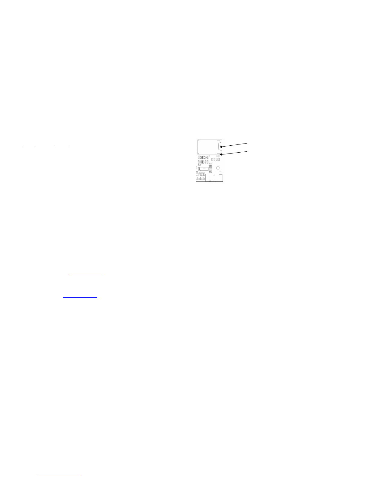
6. Connect the programming cable to the TS100, connector J17:
7. Connect power to the TS100. Once the LED´s reach idle mode commands may be issued from the Teraterm window to the
TS100. A programming session must always be started with entering of the programming password (default: admin). As long as
programming continues there is no programming timeout in the system but once the TS100 has not received any commands in a
period of approximately 5 minutes, entering the password will once again be required to continue programming.
PC programming example:
Command TS100 Reply Explanation
dt+ipassw=admin OK Enter password
dt+setpassw=asdfg OK Password is changed to asdfg
dt+rec1=? OK No receiver 1 programmed
dt+rec1=123456789 OK Receiver 1 updated to 123456789
dt+rec1=? 123456789 OK Receiver 1 is now 123456789
dt+rec1=* OK Receiver 1 is erased
dt+msg1=Test OK Message 1 changed to ”Test”
dt+msg1=? Test OK Message 1 = ”Test”
dt+msg1rec=1234 OK Send message 1 to receivers 1,2,3 and 4.
dt+msg1rec=? 1234 OK Message 1 set to be sent to receivers 1,2,3 and 4.
dt+msg1rec=* OK Erase the receiver coupling for message 1 (disable message 1)
dt+time=080526103000 OK Set system time to 2008-05-25, 10:30:00
dt+testtime1=1210 OK Set testtime 1 to 12:10. Once the system clock reaches 12:10, msg1 will be
delivered to the receivers defined with msg1rec
dt+testtime2=1400 OK Set testtime 2 to 14:00
dt+testtime3=2315 OK Set testtime 3 to 23:15
dt+testtime1=2400 OK Set testtime 4 to 24: 00 ( = disable testtime 4 since the system clock will
never reach 24:00 (goes from 23:59 to 0:00)
dt+out1=1 OK Activate output 1 (O1 is closed to GND = Supply -)
dt+out1=0 OK Deactivate output 1 (O1 is released from GND = Supply -)
dt+msg3=**0 OK Input 1 operates as an alarm input.
dt+msg3=**1 OK Input 1 is used to force the TS100 to switch to GSM regardless of the PSTN
status.
dt+rsttxt=Reset OK Reset text = ”Reset”
If reset text is entered, a reset of an alarm event, ex: the restoral of an input, will cause a new message delivery to the defined
receivers for that alarm event. The same text message will then be delivered but with the reset text attached to the alarm text.
Ex alarm message: ”Input 1”, ex reset message: ”Input 1 Reset”.
NOTE: All system parameters are stored on a non-volatile memory area meaning that all parameters will be unchanged also after
a possible power loss with the exception of the system time (used only if the unit is programmed to deliver test messages at
certain times). This means that if you want to program the TS100 from a PC prior to the actual installation occasion, this is best
solved by that all parameters are entered except the system time which may then be entered after the installation using an SMS
message.
SIM reader
Connector J17. Connect the
cable with the black wire
closest to the PCB edge.
 Loading...