

DUAL LITE CLS Series Installation Instructions Manual
CLS Series
LED Steel Exit Sign
Hubbell Lighting, Inc. Life Safety Products • www.dual-lite.com
Copyright© Hubbell Lighting, Inc., All Rights Reserved • Specications subject to change without notice. • Printed in U.S.A.
93041209 02/17
IMPORTANT SAFEGUARDS
When using electrical equipment, basic safety precautions should always be followed including the following.
READ AND FOLLOW ALL SAFETY INSTRUCTIONS
1. Do not let power supply cords touch hot surfaces.
2. Do not mount near gas or electric heaters.
3. Equipment should be mounted in locations and at heights where it will not readily be subject to tampering
by unauthorized personnel.
4. The use of accessory equipment not authorized by the manufacturer may cause an unsafe condition.
5. Do not use this equipment for other than its intended purpose.
6. Servicing of this equipment should be performed by qualied service personnel.
7. Test cycling: the Life Safety Code (NFPA 101) requires testing of emergency exit signs once a month for a
minimum of 30 seconds and once a year for a minimum of 90 minutes.
INSTALLER:
•SEE UNIT LABEL FOR ADDITIONAL MODEL SPECIFICATIONS
•SAVE THESE INSTRUCTIONS FOR USE BY OWNER/OCCUPANT
WARNING – This product contains chemicals known to the State of California to cause cancer, birth defects and/or other
reproductive harm. Thoroughly wash hands after installing, handling, cleaning, or otherwise touching this product.
INSTALLATION INSTRUCTIONS
General
1. This Exit may be shipped with an EXTRA FACE PLATE AND RED LENS to make sign double face. Replace the
BACK PLATE with the extra face plate & lens at the start of the installation process if the application calls for a
double face sign.
BACK MOUNT INSTALLATION (Figure 1)
Step 1. Extend unswitched 24 hour AC supply of rated voltage to junction box (NOT INCLUDED). Leave at least
18 inches of stock.
Step 2. Remove retainer screw from side of sign. Remove side panel and lens.
Step 3. Remove 7/8” DIA KO and required mounting pattern from back plate. Use bushing provided to protect
wries from metal edges. Secure wires using cable tie. Feed wires through 7/8” DIA KO bushing.
Step 4. Connect ground in accordance with local codes. Connect wires per schematic and color code as follows:
Line 100- 300V- ORANGE;NEUTRAL - WHITE. Cap unused line lead.
Step 5. Mount sign securely to junction box using mounting plate and screws provided.
Step 6. For battery backup models, connect battery leads. Turn on AC supply and operate test switch. LED
lamps will stay on in AC mode and remain on in Emergency mode. For AC only models, turn ON AC supply.
Step 7. Carefully slide glass into sign frame channel and replace end panel and retainer screw.
CEILING or END MOUNT (Figure 2)
Step 1. Follow Steps 1 and 2 of back mount instructions
Step 2. Knock out the appropriate mounting pattern on top or side of unit to accommodate canopy. Use plastic
bushings provided to protect wires from metal edges.
Step 3. FASTEN CANOPY TO SIGN BY MEANS OF (2) SCREWS, STAR WASHERS AND NUTS.
Step 4. Secure mounting plate to junction box by choosing proper slots and using screws supplied with junction
box. {NOT INCLUDED}
Step 5. Feed wires through canopy and connect to supply following step 4 of back-mount instructions.
Step 6. Mount sign with canopy to Junction box using screws proded.
Step 7. Follow steps 6 to 7 of back-mount instructions.
Important
When relamping, only use LED lightsource specied in the sign. Using other LED light source may result in
transformer damage or unsafe conditions. For battery backup models, battery in unit may not be fully charged.
After electricity is connected to the unit, let the battery charge up for at least 2-4 hrs. The normal operation of the
unit should take eect.
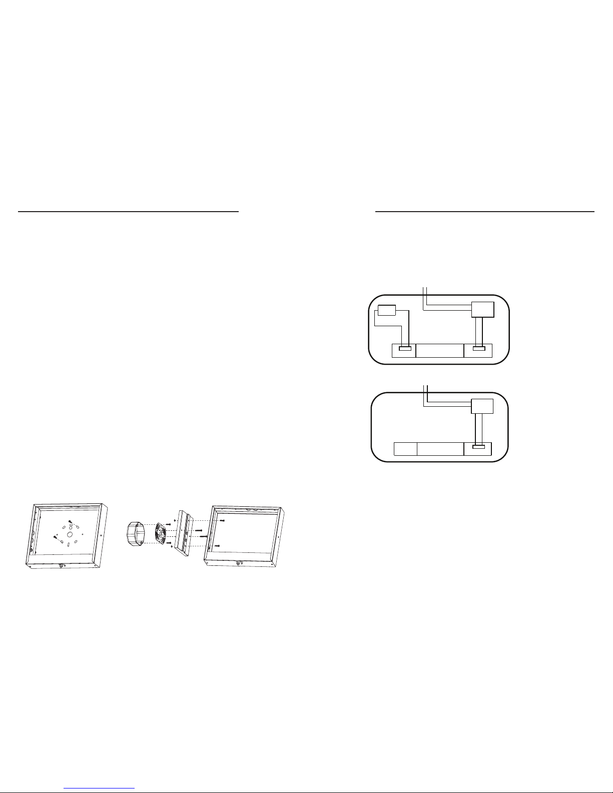
Wiring Diagram
Note:
Properly insulate the unused lead with a wire nut or other approved means.
Warning:
Unused wires must be capped using enclosed wire nuts.
2 .GIF1 .GIF
YLNO CAPUKCAB YRETTAB
BAT.
LED BOARD
POWER
BOARD
WHITE COM
ORANGE 100-300VAC
POWER
BOARD
WHITE COM
ORANGE 100-300VAC
LED BOARD
YLNO CAPUKCAB YRETTAB
YLNO CAPUKCAB YRETTAB
POWER
BOARD
WHITE COM
ORANGE 100-300VAC
LED BOARD
YLNO CAPUKCAB YRETTAB
 Loading...