

DualLite CLSC Quick Start Manual
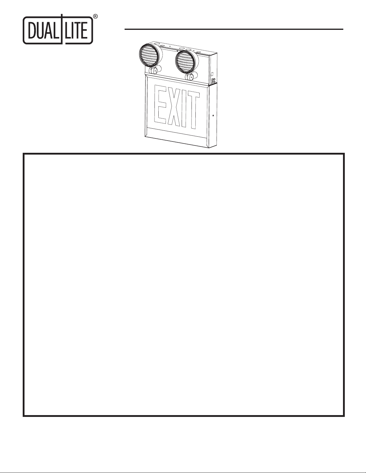
CLSC
Chicago Approved Battery Backup LED Exit & Unit Combo
No Panel Version
IMPORTANT SAFEGUARDS
When using electrical equipment, basic safety precautions should
always be followed including the following.
READ AND FOLLOW ALL SAFETY
INSTRUCTIONS
Warning: FAILURE TO FOLLOW THESE INSTRUCTIONS AND WARNINGS MAY RESULT IN DEATH,
SERIOUS INJURY OR SIGNIFICANT PROPERTY DAMAGE - For your protection, read and follow these
warnings and instructions carefully before installing or maintaining this equipment. These instructions
do not attempt to cover all installation and maintenance situations
Warning: RISK OF ELECTRIC SHOCK. NEVER CONNECT TO, DISCONNECT
FROM, OR SERVICE WHILE EQUIPMENT IS ENERGIZED.
Warning: RISK OF FIRE - Lamps are hot. Keep combustible material away from hot parts. Observe
lamp manufacturer’s warnings, recommendations and restrictions on lamp operation and maintenance.
Make sure lamps are correctly installed.
Warning: DO NOT USE ABRASIVE MATERIALS OR OTHER SOLVENTS. USE OF THESE
SUBSTANCES MAY DAMAGE FIXTURE, WHICH MAY RESULT IN PERSONAL INJURY.
Warning: RISK OF PERSONAL INJURY. This product may have sharp edges. Wear gloves to prevent
cuts or abrasions when removing from carton, handling, installing and maintaining this product.
• Before wiring to power supply, turn off electricity at fuse or circuit breaker.
• Disconnect A.C. power and unplug battery before servicing.
• Consult your local building codes for approved wiring and installation.
• May be used outdoors under cover (0°C - 50°C; 32°F - 122°F).
• Do not let power supply cord touch hot surfaces.
• Do not mount near gas or electric heaters.
• Do not install a damaged fi xture.
• This product must be installed in accordance with the applicable installation codes and ordinances.
• All service shall be performed by qualifi ed service personnel. This product must be installed and maintained in accordance with the applicable
installation codes by a person familiar with the construction operation of the product and the hazards involved.
• Equipment should be mounted in locations and at heights where it will not be subject to tampering by unauthorized personnel.
• The use of accessory equipment not recommended by the manufacturer will void product listing and warranty and may cause an unsafe condition.
• Do not use this equipment for anything other than its intended use.
• The AC voltage rating of this equipment is specifi ed on the product label. Do not connect equipment to any other voltage.
WARNING – This product contains chemicals known to the State of California to cause cancer, birth
defects and/or other reproductive harm. Thoroughly wash hands after installing, handling, cleaning,
or otherwise touching this product.

INSTALLATION
Note: This EXIT xture may be shipped with an extra FACE PANEL to make the sign double face. Replace the
BACKPLATE with the extra FACE PANEL at the start of the installation process if the application calls for a double
face sign.
BACK MOUNT INSTALLATION (Fig 1.)
1. Remove retainer screw from right side of sign. Remove side panel and mounting canopy and set aside.
2. Remove retainer screw from the front cover of the unit. Remove the front cover and set aside.
3. Remove 7/8” diameter KNOCK OUT mounting hole located at the top portion of back plate. Use busings
provided to protect wires from metal edge. Install mounting pan and cable tie to back plate. Secure wires using
cable tie. Feed wires through 7/8” diameter KNOCK OUT bushing.
4. Adhering to National, State and Local codes, make wiring connection. For 120V, use black and white wires and
for 277V, use red/orange and white wires. WARNING: Properly insulate the unused leads with wire nuts (provided)
or other approved methods.
5. Push wire connections into the Junction box.
6. Mount sign equipment securely in place on the wall. Two additional KEY HOLE mounting holes are locatred at the
top of the unit housing in addition to the Junction box mounting holes. These two additional mounting slot holes
must be used. Additional chain support may be required by local codes.
7. Carefully replace the glass into the sign frame channel and replace end panel and retainer screw.
8. Connect battery in unit by connecting the RED(+) lead from the PC board assembly to the positive (+) terminal
on the battery and the BLACK (-) lead from PC board assembly to the negative (-) battery terminal. CAUTION:
Observe polarity. Failure to connect the battery properly will result in equipment failure and an unsafe condition.
NOTE: Emergency lights willl NOT com ON at this time.
9. Replace and secure the front cover.
10. Energize the sign xture with AC supply. The charge indicator lights will illuminate.
11. Adjust and focus the lighting heads as required.
CEILING or END MOUNT INSTALLATION (Fig. 2)
NOTE: Cannot be right-side end mounted
12. Remove retainer screw from right side of sign. Remove side panel and mounting canopy and set aside.
13. Remove retainer screw from the front cover of the unit. Remove the front cover and set aside.
14. Remove both 7/8” diameter KNOCK OUT mounting holes located on the frame. For ceiling mount, knock out
mounting holes will be located on top of the frame. For left-side wall mount, knock out mounting holes will be
located on the side of the frame.
15. Thread 7/8” nuts (2 required, not included) onto 7/8” pipe nipples (2 required, not included). Slide pipe nipples
through canopy holes.
16. Place screws (provided) in holes on the canopy.
17. Route wires through knock outs in unit frame (ceiling mount) or in EXIT frame (side mount), pipe nuts and metal
mounting plate.
18. Adhering to National, State and Local codes, make wiring connection. For 120V, use black and white wires and
for 277V, use red/orange and white wires. WARNING: Properly insulate the unused leads with wire nuts (provided)
or other approved methods.
19. Push wire connections into the Junction box. Secure mounting plate to Junction box (hardware not included).
20. Secure the canopy to the steel mounting plate with screws installed in Step 5.
21. Place pipe nipples through the mounting holes of the frame until the canopy is touching the frame. Thread a
second nut (not included) onto each of the pipe nipples on the inside of the housing and lock the canopy into
place. Once canopy is locked into position there will not be any side-to-side movement on the canopy.
22. Carefully replace the glass into the sign frame channel and replace end panel and retainer screw.
23. Connect battery in unit by connecting the RED(+) lead from the PC board assembly to the positive (+) terminal
on the battery and the BLACK (-) lead from PC board assembly to the negative (-) battery terminal. CAUTION:
Observe polarity. Failure to connect the battery properly will result in equipment failure and an unsafe condition.
NOTE: Emergency lights willl NOT com ON at this time.
13. Replace and secure the front cover.
14. Energize the sign xture with AC supply. The charge indicator lights will illuminate.
15. Adjust and focus the lighting heads as required.
 Loading...