

Page 1

DUALi
Inc. All rights reserved. You are strictly prohibited to copy, disclose, distribute, or use
this document in part or as a whole for any purposes other than those for which this document is disclosed. This
onfidential information and other intellectual property rights of DUALi Inc.
int
ellectual property
DE-960 User Manual
DUA
Li Inc.
Document Version: 1.00
Last Revised Date: 16th. DEC 2011
Copy
right ⓒ 2016
document is copyrighted and contains c
Any
unauthorized use, copy, disclosure or distribution constitutes infringement of DUALi’s
Page 2

DUALi
application or service at any time without notice. DUALi provides customer assistance in various technical
areas, but does not have full access to data concerning the use and applications of customer's products.
Therefore, DUALi assumes no liability and is not responsible for customer applications or software design
or performance relating to systems or applications incorporating DUALi products. In addition, DUALi
assumes no liability and is not responsible for infringement of patents and/or any other intellectual or
industrial property rights of third parties, which may result from assistance provided by DUALi.
Composition of the information in this manual has been done to the best of our knowledge. DUALi does not
guarantee the correctness and completeness of the details given in this manual and may not be held liable
for damages ensuing from incorrect or incomplete information. Since, despite all our efforts, errors may not
be completely avoided, we are always grateful for your useful tips.
We have our development center in South Korea to provide technical support. For any technical assistance
can contact our technical support team as below;
Tel: +82 31 213 0074
Inc. reserves the right to make changes to its applications or services or to discontinue any
e-mail : [email protected]
FeliCa™ is registered trademark of SONY Corporation.
Mifare® is registered trademarks of NXP Semiconductors
Page 3

DE-960 User
’s Manual
Revision History
2016.12.16
(Ver. 1.00) : First Release
© Copyright 2000-2016 DUALi Inc.
Version : 1.00
3
DUALi Inc.
(http://www.duali.com)
Page 4

DE-960 User
’s Manual
CONTENTS
1 Introdu
2 Contents Confirmation...................................................................................................................... 5
3 Hardware
4 Installation
5 Connectio
6 Opera
7 Outp
8 Wiegand
9 Funct
10
11 Warranty & Service ......................................................................................................................... 19
ction ....................................................................................................................................... 5
Specification ..................................................................................................................... 5
......................................................................................................................................... 5
n diagram ......................................................................................................................... 7
tion & Usage ............................................................................................................................ 8
ut format .................................................................................................................................. 10
output timing and level .................................................................................................... 11
ion configuration (Communication setting) ......................................................................... 12
ion configuration (KEY setting) ........................................................................................... 16
Funt
Version : 1.00
4
DUALi Inc.
(http://www.duali.com)
Page 5
ma
chine screw
1
Introduction
DE-960 User
’s Manual
DE-960 i
32/34/64/66-bit Wiegand format with a host communication which is the most widespread system. It’s
applicable to various system such as access control, time attendance, parking management or e-ID system.
s refined design of proximity reader which supports contactless (ISO14443 A). It supports
2
Conten
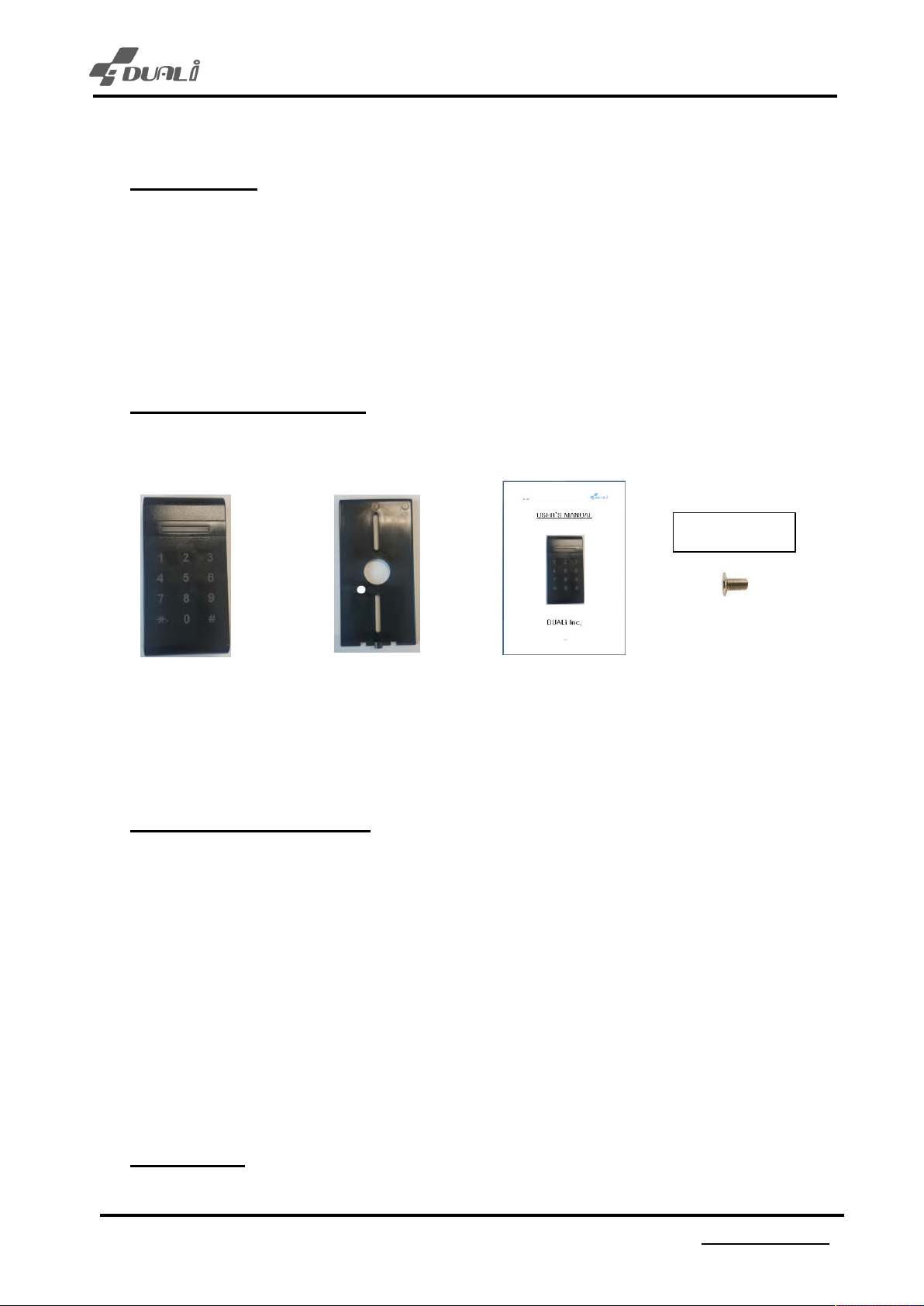
- The f
Reader Bracket Manual Screw
ts Confirmation
ollowing items are contained in DE-960 package.
3*4 Flat head
(1 ea) (1 ea) (1 ea) (1 ea)
3
Hard
Read Range Up to 5cm
Input Voltage/Current DC 12V, MAX 150mA(12V)
LED/Beeper 2 LEDs(Red, Blue) / 12 Key LED(White) / Magnetic Buzzer
Color Black(Body)
Operating Environment -20℃ ~ +60℃, 10~90% Humidity
Overall Size(WxHxD) 60 x 115 x 25mm
Output Format 32 / 34 / 64/ 66 bit Wiegand, RS-232/485(option)
4
Installat
ware Specification
ion
Version : 1.00
5
DUALi Inc.
(http://www.duali.com)
Page 6
DE-960 User
’s Manual
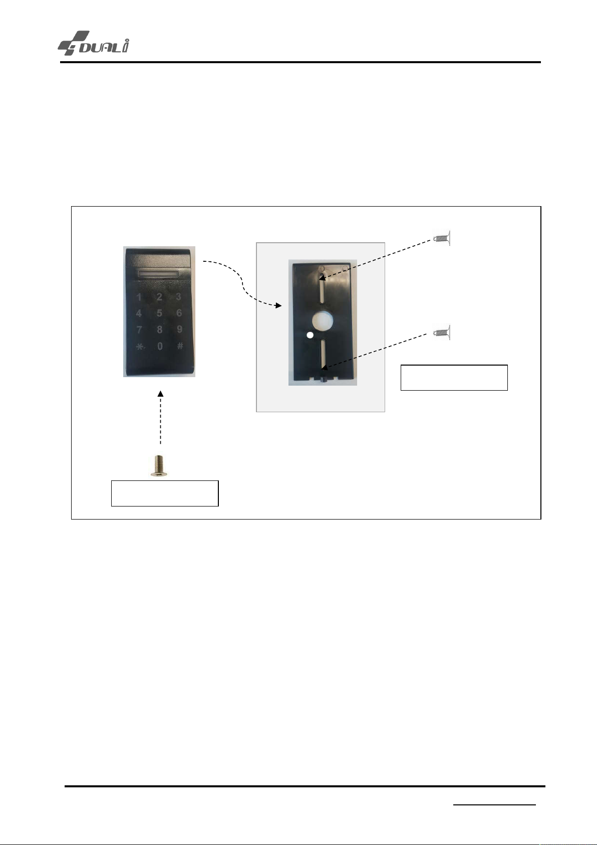
1. Place th
2. Connect the power and communication cable to DE-960’s terminal block.
(Refer to chapter 5, Connection diagram)
3. Tilt the device slightly and insert to the wall mount from the top. Fix it tightly with 3*4 flat head machine
screw.
e wall mount bracket on the wall and fix it tightly with screw (Φ4mm Flat head) – 4nos
Φ4mm F
lat head screw
lat head machine
3*4 F
<Picture
※ Caut
- Do not push
- Screw has to be selected depending on the wall’s material and condition
- Place the reader to flat panel between the wall mount bracket and the wall.
It could cause a problem to assemble the device if the bracket is bent.
- Card readi
ion
the device/wall mount bracket too hard when fixing it to the wall.
ng distance can be short if the wall is made of steel.
1. Installation>
Version : 1.00
6
DUALi Inc.
(http://www.duali.com)
Page 7
5
Connection diagram
DE-960 User
’s Manual
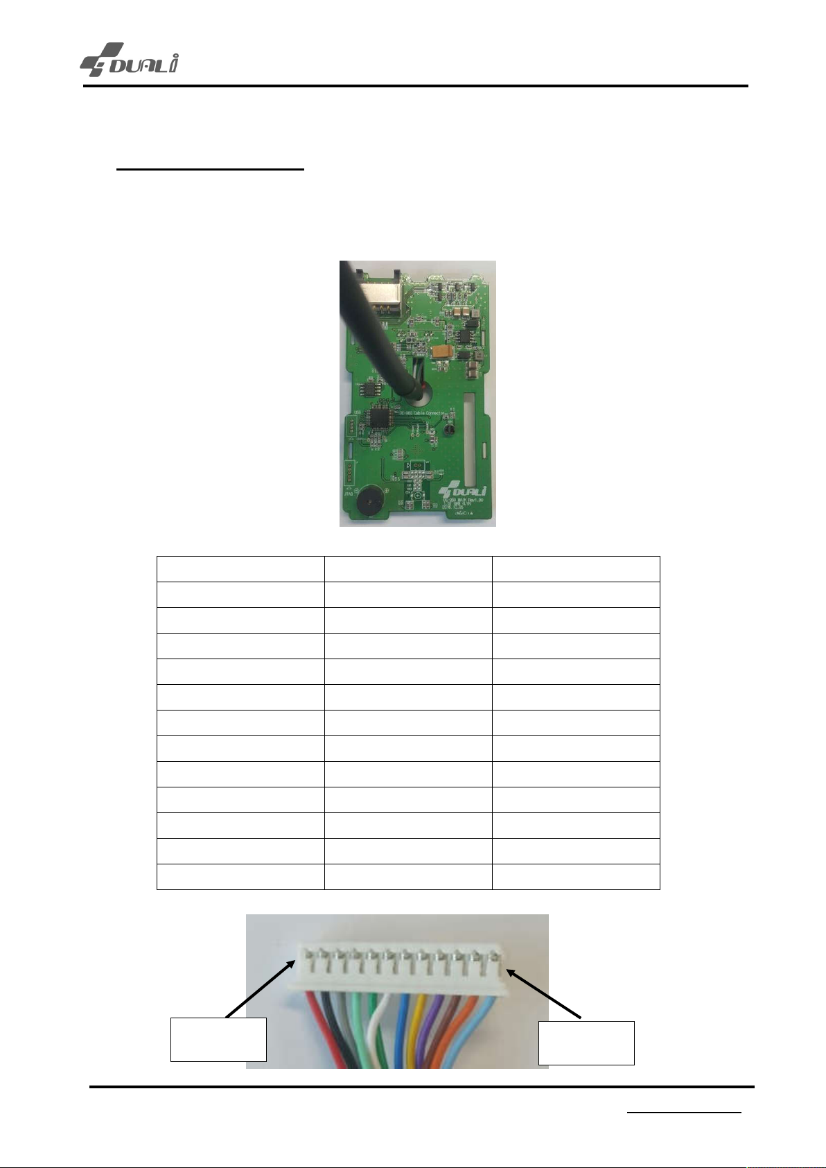
Depending
the below diagram for the connection.
on cable connection, you can make choice among RS-485 / RS-232 / Wiegand. Please refer to
PIN NA
ME COLOR PIN NUMBER
PWR_IN RED 1
PWR_GND BLACK 2
RS232_RX GRAY 3
RS232_TX JADE 4
WGD_D0 GREEN 5
WGD_D1 WHITE 6
PWR_GND BLUE 7
LED BROWN 8
BEEP YELLOW 9
TAMPER VIOLET 10
RS485+ ORANGE 11
RS485- SKY BLUE 12
Version : 1.00
No.1 PIN
7
No.12 PIN
DUALi Inc.
(http://www.duali.com)
Page 8
6
Operation & Usage
DE-960 User
’s Manual
1. Once i
2. When user present authorized contactless card to the reader, the reader makes 1 time beep
3. When an unauthorized card is presented on the reader, RED LED will be blinking.
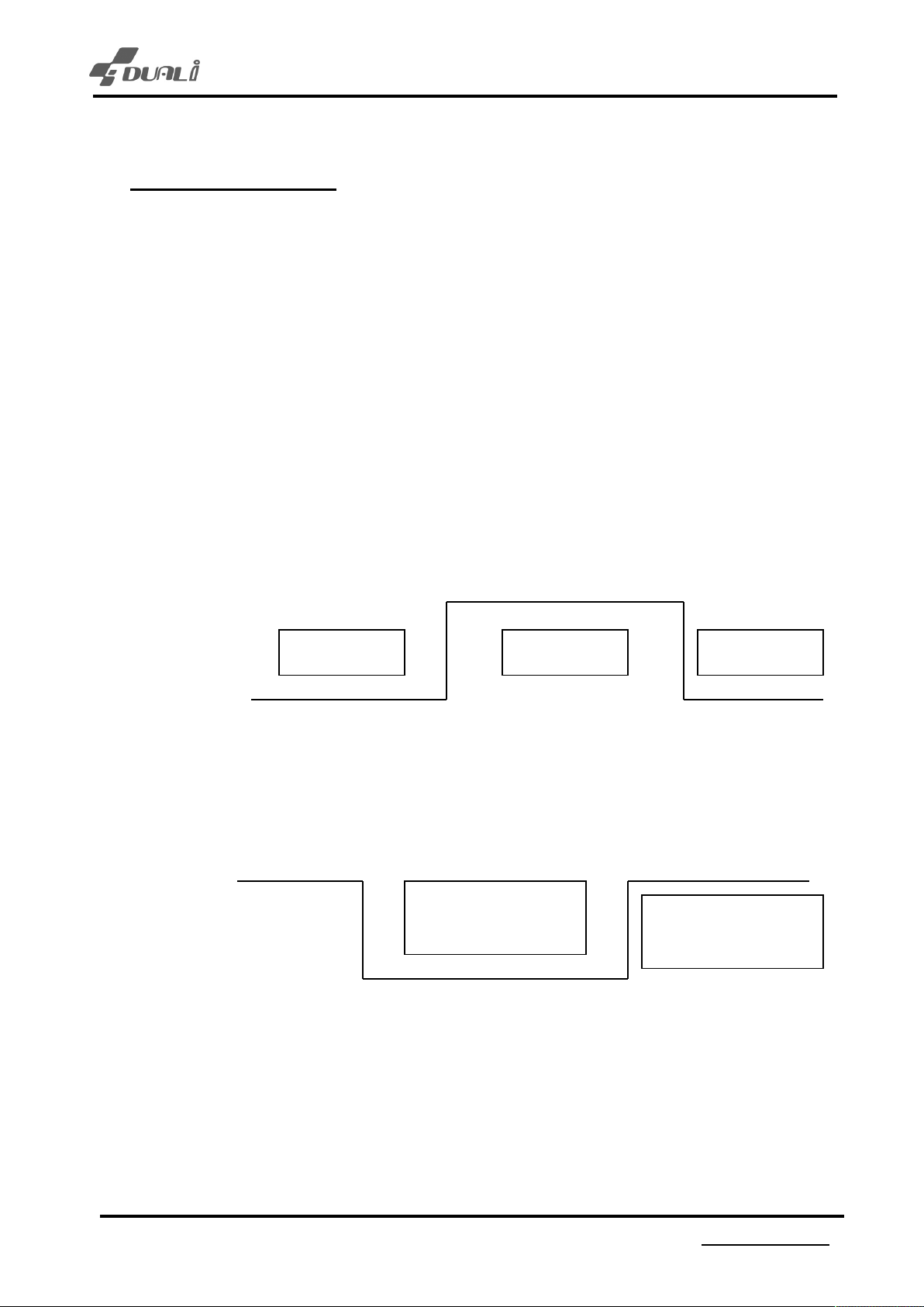
4. Tamper (TAMP) :
nput power to device, white LED on KEY pad is turned on and off, after that, BLUE &
RED LED are turned on.
sound and 2 times of turning RED LED. It sends card’s data to access controller through
Wiegand data line.
Reader makes alarm when its CASE is forced to open. It also makes TAMPER signal to
access controller. In case of closed CASE, TAMPER line (SKY-Blue Line) shows 0V and
otherwise(open) shows 3.3V.
3.3V
GND
CASE C
LOSE
CASE OPE
N
CASE C
LOSE
5. LED Control :
Reader tuns on RED LED when LED Signal(PINK) with 0V. In case of 5V, BLUE LED will be
on.
5V
GND
RED LE
BLUE LED OFF
D ON
RED LED OFF
BLUE LED ON
Version : 1.00
8
DUALi Inc.
(http://www.duali.com)
Page 9

DE-960 User
’s Manual
6. Buzzer
Control :
Reader makes beep sound when BEEP Signal(BROWN) with 0V.
5V
GND
BUZZER OF
F
BUZZER O
N
BUZZER OF
F
Version : 1.00
9
DUALi Inc.
(http://www.duali.com)
Page 10
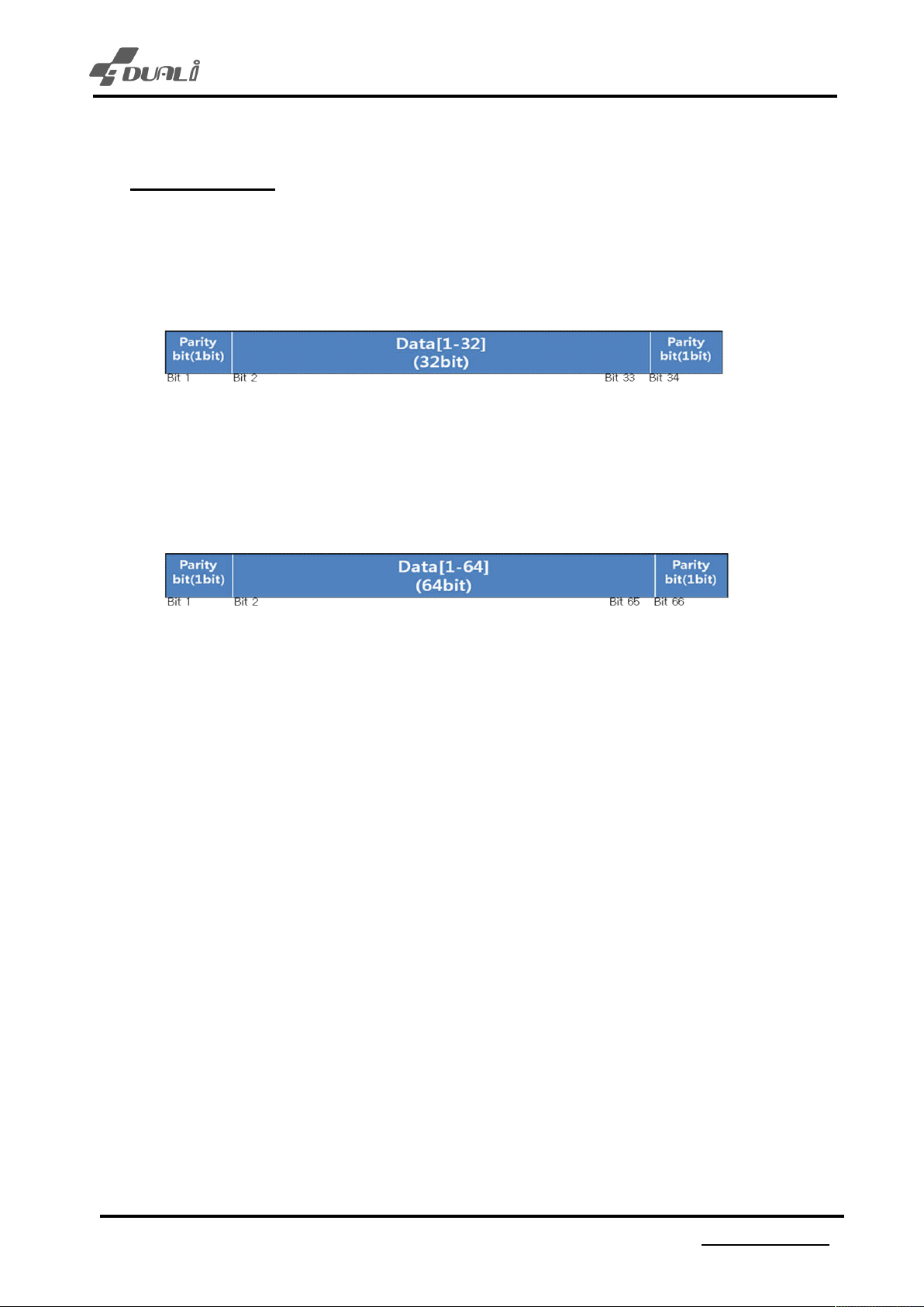
7
Output format
7-1. Data format
- Data format can be decided by setting. (Refer to chapter 8)
<34bit>
DE-960 User
’s Manual
First
Data[1-32] : ID number(transmission data)
Last Bit 34 : Odd parity of bit 18 ~ bit 33
Bit 1 : Even parity of bit 2 ~ bit 17
<66bit>
First B
Data[1-64] : ID number(transmission data)
FeliCa™ card – IDM data(8bytes)
Mifare® card – Card serial number(4bytes)+0x00(4bytes)
Last Bit 66 : Odd parity of bit 34 ~ bit 65(Data[33-64])
it 1 : Even parity of bit 2 ~ bit 33(Data[1-32])
<32bit>
Data[0
-31] : ID number(transmission data)
<64bit>
Data[0
FeliCa™ card – IDM data(8bytes)
Mifare® card – Card serial number(4bytes)+0x00(4bytes)
Version : 1.00
-63] :
10
DUALi Inc.
(http://www.duali.com)
Page 11
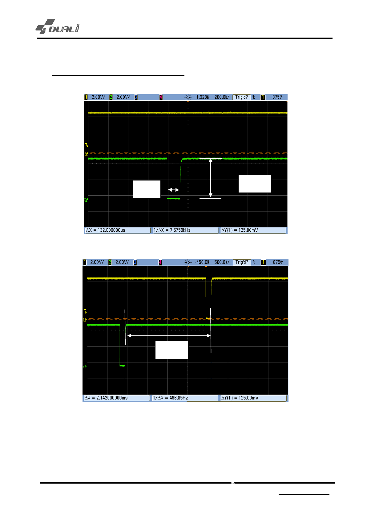
8
Wiegand output timing and level
DE-960 User
’s Manual
132uS
5.00V
2.14mS
Version : 1.00
11
DUALi Inc.
(http://www.duali.com)
Page 12
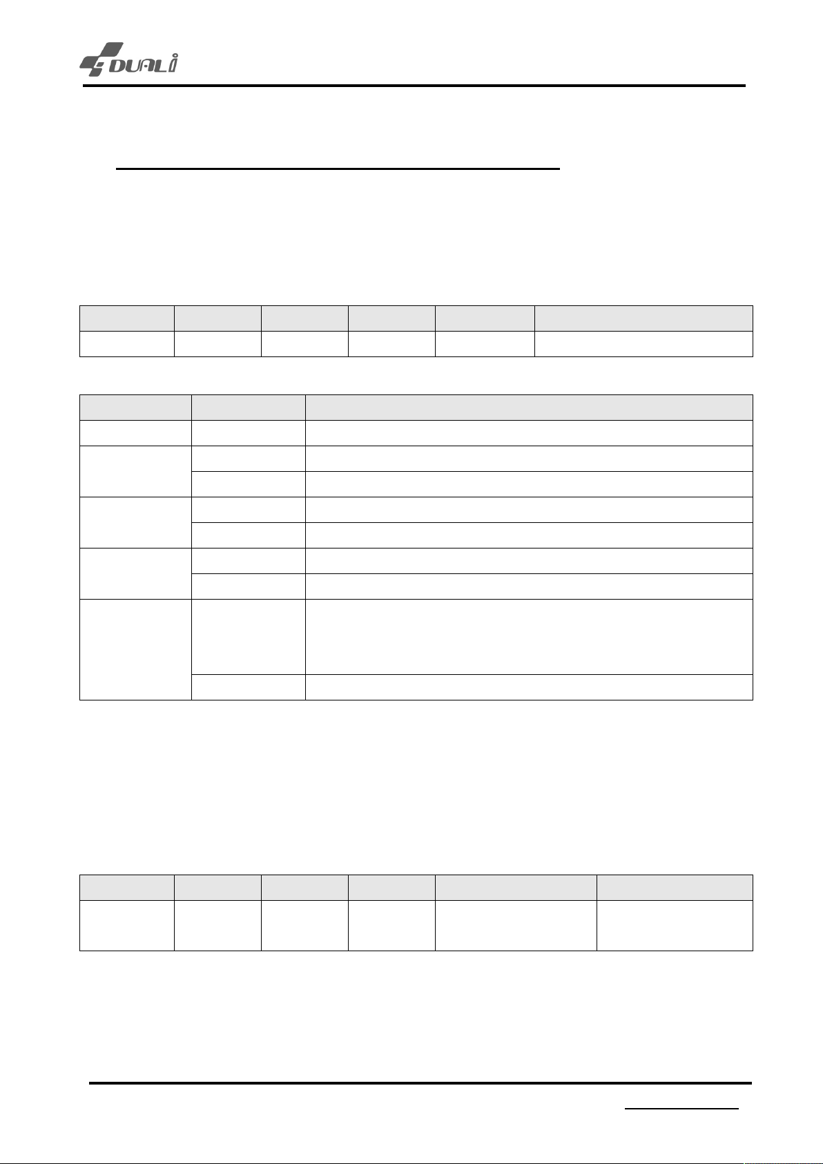
9
Function configuration (Communication setting)
9.1
Wiegand option set
ing is the communication frame for wiegand option setting. Since it is saved in flash memory
Follow
after the first setting, the reader does not need to be set again.
(9600bps, 8 data, no parity, 1 stop bit)
DE-960 User
’s Manual
STX
0x02 0x00 0x02 0xE0 DAT
DAT
A[0]
Bit
7~4 RFU RFU
Bit
3
Bit2
1
Bit
Bit
0
LENH
St
ate
0 4byte ID(32 or 34bit) depend on parity setting(No.2)
1 8byte ID(64 or 66bit) depend on parity setting(No.2)
0 Parity Send(34 or 66bit) depend on ID bytes(No.1)
1 Parit
0 Forward ID byte order
1 Revers
0
1 Read MIF
LENL
CMD DAT
A[0] LENL ^ CMD ^ DATA[0]
( ^ : exc
Reader enters security mode when SAM exists when boot.)
lusive oring)
y Omit(32 or 64bit) depend on ID bytes(No.1)
Not Read MIFARE card in Security Mode
(Security Mode : SAM authentication for FeliCa,
ARE card in Security Mode
A
Descript
ion
e ID byte order
LRC
9.2
LED option set
ing is the communication frame for LED color setting. Since it is saved in flash memory after the
Follow
first setting, the reader does not need to be set again.
(9600bps, 8 data, no parity, 1 stop bit)
STX LENH LENL CMD DATA[0] LRC
0x02 0x00 0x02 0xE1 0- BLU
1- RED LED ON
E LED ON
Version : 1.00
12
DUALi Inc.
(http://www.duali.com)
LENL
DATA[0]
^ CMD ^
Page 13
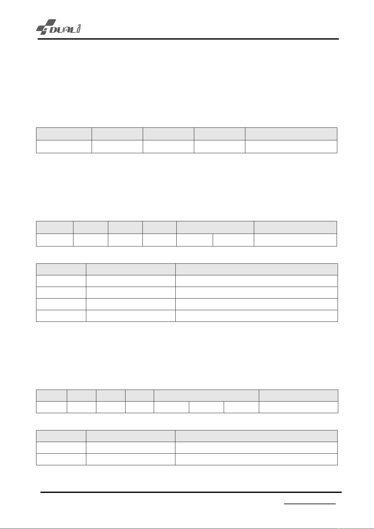
DE-960 User
9.3
Automatic Card Detection Disable
ing is the communication frame for automatic card detection disable setting
Follow
This command controls the automatic card detection function. It is used when controlling DE-960 from
host device like PC.
(9600bps, 8 data, no parity, 1 stop bit)
STX LENH LENL CMD LRC
0x02 0x00 0x01 0xEF 0xEE
9.4
KEY Mode option set
ing is the communication frame for Key mode setting. Since it is saved in flash memory after the
Follow
first setting, the reader does not need to be set again.
(9600bps, 8 data, no parity, 1 stop bit)
’s Manual
STX
0x02 0x00 0x02 0xE3 0x01 DAT
DAT
A[0]
0x00 Direct Mode
0x01 Buffer Mode + PIN Input KEY Buffer mode – CARD detect & PIN
0x02 Direct Mode Input KEY Direct mode
0x03 Buffer Mode Input KEY Buffer mode
9.5
Following is the PASS Buffer communication frame for setting. Since it is saved in flash memory after
the first setting, the reader does not need to be set again.
(9600bps, 8 data, no parity, 1 stop bit)
STX
LENH
LENL
St
ate
CMD DAT
( ^ : exc
+ PIN Input KEY Direct mode – CARD detect & PIN
PASS Buffer Length option set
LENH
LENL
CMD DAT
lusive oring)
A
A
A[1] LENL ^ CMD ^ DATA[0]
Descript
ion
LRC
LRC
0x02 0x00 0x02 0xE3 0x02 DATA[1] DATA[2] LENL ^ CMD ^ DATA[0]
( ^ : exclusive oring)
A[x]
DAT
DAT
A[1] MINIMUM Length Set password minimum length (Range: 1~11)
DAT
A[2] MAXIMUM Length Set password maximum length (Range: DATA[1]~12)
Version : 1.00
St
ate
13
Descript
DUALi Inc.
ion
(http://www.duali.com)
Page 14
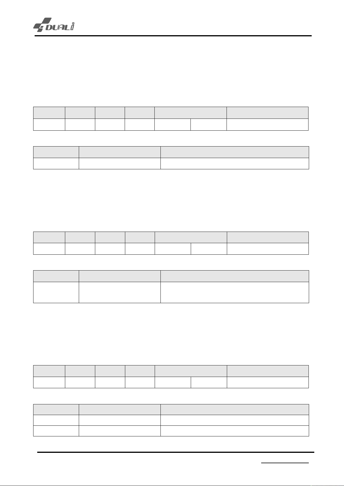
9.6
KEY Timeout option set
ing is the communication frame for key time out option setting. Since it is saved in flash memory
Follow
after the first setting, the reader does not need to be set again.
(9600bps, 8 data, no parity, 1 stop bit)
DE-960 User
’s Manual
STX
0x02 0x00 0x02 0xE3 0x03 DAT
DAT
0x01~0x0A Touch Key Timeout Touch Key timeout setting (Range: 0x01~0x0A)
9.7
Following is the communication frame for Touch Key sensitive option setting. Since it is saved in flash
memory after the first setting, the reader does not need to be set again.
(9600bps, 8 data, no parity, 1 stop bit)
STX
0x02 0x00 0x02 0xE3 0x04 DATA[1] LENL ^ CMD ^ DATA[0]
DATA[1] State Description
A[1]
LENH
LENL
St
ate
KEY Sensitive option set
LENH
LENL
CMD DAT
( ^ : exclusive oring)
CMD DAT
( ^ : excl
usive oring)
A
A[1] LENL ^ CMD ^ DATA[0]
Descript
A
ion
LRC
LRC
0x01~0x04
9.8
Follow
memory after the first setting, the reader does not need to be set again.
(9600bps, 8 data, no parity, 1 stop bit)
STX
0x02 0x00 0x02 0xE3 0x05 DAT
DAT
0x00 BUZZER OF
0x01 BUZZER ON
Touch Key Sensitive
(Lower value is more sensitive)
KEY Push Buzzer option set
ing is the communication frame for Key push buzzer option setting. Since it is saved in flash
A[1]
LENH
LENL
St
CMD DAT
( ^ : excl
ate
F Touch KEY, buzzer off
Touch KEY, buzzer on
usive oring)
A
Touch KEY sensitive set
LRC
A[1] LENL ^ CMD ^ DATA[0]
Descript
ion
Version : 1.00
14
DUALi Inc.
(http://www.duali.com)
Page 15
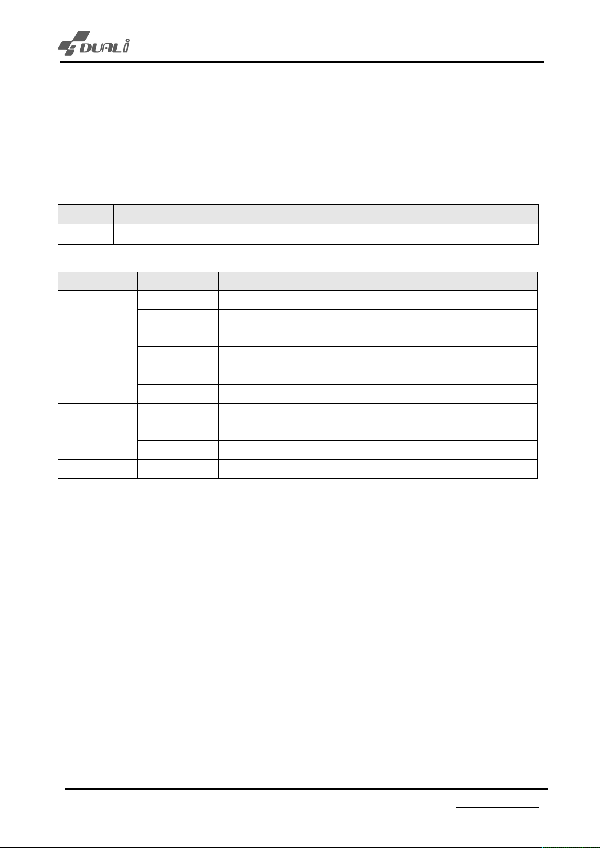
DE-960 User
9.9
RF Scan option set
ing is the communication frame for RF Scan setting. Since it is saved in flash memory after the
Follow
first setting, the reader does not need to be set again
(9600bps, 8 data, no parity, 1 stop bit)
STX LENH LENL CMD DATA LRC
’s Manual
0x02 0x00 0x02 0xE3 0x06 DAT
( ^ : excl
DATA[1] State Description
Bit7
Bit
6
5
Bit
Bit4 RFU RFU
Bit3
Bit2 ~ Bit0 RFU RFU
0 TYPE-A / MIFARE Scan Off
1 TY
0 TYPE-B Scan Off
1 TY
0 FELICA Scan Off
1 FELICA
0 15693 Scan Off
1 15693 Scan ON
usive oring)
PE-A / MIFARE Scan ON
A[1] LENL ^ CMD ^ DATA[0]
PE-B Scan ON
Scan ON
Version : 1.00
15
DUALi Inc.
(http://www.duali.com)
Page 16
10
Funtion configuration (KEY setting)
10.1
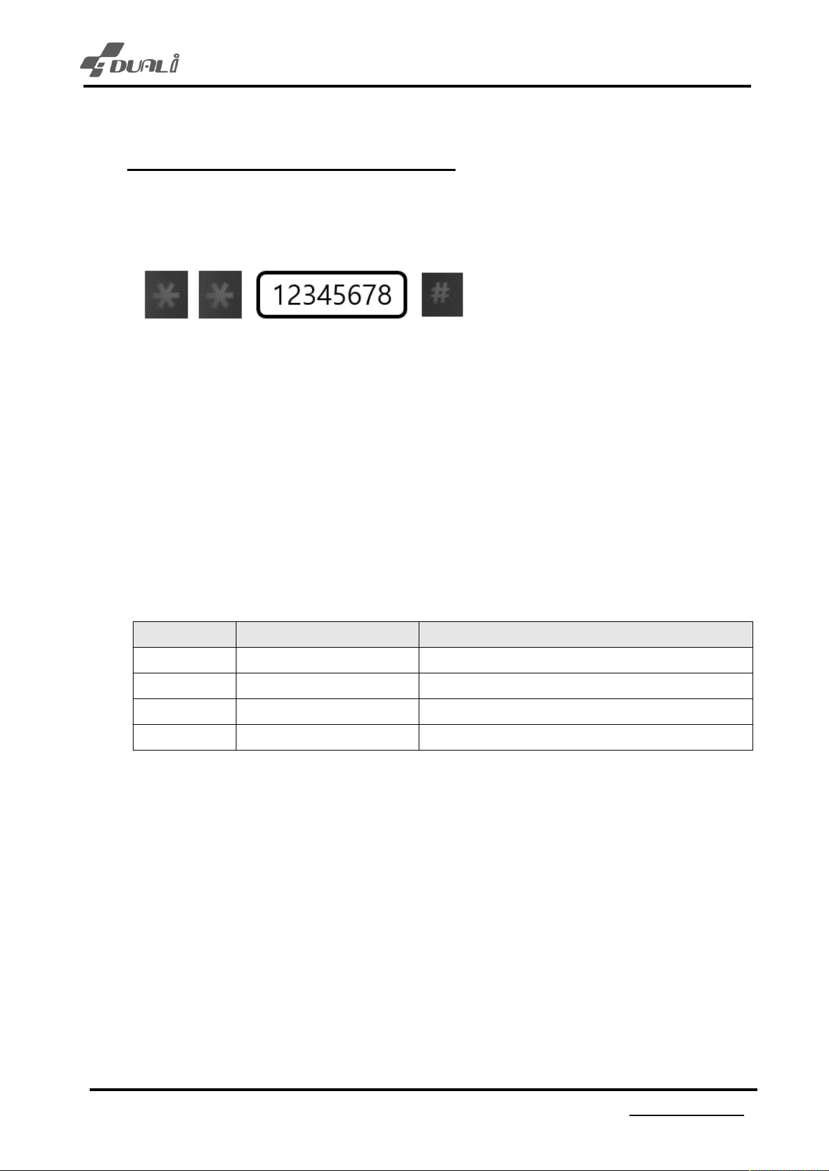
Enter setting mode
- Through
- How to enter setting mode
DE-960 Touch KEY, it is possible to enter setting mode.
DE-960 User
’s Manual
1. Wh
2. Input password (Max. 8 digit)
3. After input, press “#” then RED/BLUE LED will be blinking and finally enter setting mode..
4. Input your password to change.
5. Press “*” to finish.
6. If there is no more input during 10sec, it automatically finishes.
- PASSWORD can be changed through F/W build.
10.2
- Wh
- After entering, press option number below.
en press “*” “*” (two times), buzzer sound and it enter “password input mode”
KEY Mode setting
en RED/BLUE RED keep blinking, press “1” to enter KEY mode setting menu.
KEY St
1 Direct Mode +
2 Buf
3 Direct Mode
4 Buf
ate
PIN Input KEY Direct mode – CARD detect & PIN
fer Mode + PIN Input KEY Buffer mode – CARD detect & PIN
Input KEY Direct mode
fer Mode Input KEY Buffer mode
Descript
ion
- After press option number and press “#” to save option to flash memory. Then DE-960 will reboot.
- Press“*” to return to setting menu.
- If press the number except 1~4, it will set to No.1(Direct mode + PIN)
Version : 1.00
16
DUALi Inc.
(http://www.duali.com)
Page 17
DE-960 User
10.3
Default LED setting
- Wh
- After entering, press option number below.
- After press option number and press “#” to save option to flash memory. Then DE-960 will reboot.
- Press“*” to return to setting menu.
- If press the number except 1~2, it will set to No.1(Defualt LED RED)
10.4
- Wh
- After entering, press option number below.
en RED/BLUE RED keep blinking, press “2” to enter default LED setting menu.
KEY St
1 Defaul
2 Defaul
t LED BLUE Default LED BLUE
ate
t LED RED Default LED RED
Descript
ion
KEY Push Buzzer setting
en RED/BLUE RED keep blinking, press “3” to enter KEY push buzzer setting menu.
’s Manual
KEY St
1 KEY
- After press option number and press “#” to save option to flash memory. Then DE-960 will reboot.
- Press“*” to return to setting menu.
- If press the number except 1~2, it will set to No.1(KEY Push Buzzer ON)
2 Key
ate
Push Buzzer ON Buzzer turns on when press KEY
Push Buzzer OFF Buzzer turns off when press KEY
Descript
ion
Version : 1.00
17
DUALi Inc.
(http://www.duali.com)
Page 18
DE-960 User
10.5
Wiegand Length setting
- Wh
- After entering, press option number below.
- After press option number and press “#” to save option to flash memory. Then DE-960 will reboot.
- Press“*” to return to setting menu.
- If press the number except 1~4, it will set to No.1(Card Wiegand Data 32bit)
en RED/BLUE RED keep blinking, press “4” to enter Wiegand setting menu.
KEY St
1 Wie
2 Wie
3 Wiegand 64Bit Card Wiegand Data 64bit
4 Wie
ate
gand 32Bit Card Wiegand Data 32bit
gand 34Bit Card Wiegand Data 34bit
gand 66Bit Card Wiegand Data 66bit
Descript
ion
’s Manual
10.6
Wiegand Data Foward / Reverse setting
- Wh
- After entering, press option number below.
-
- After press option number and press “#” to save option to flash memory. Then DE-960 will reboot.
- Press“*” to return to setting menu.
- If press the number except 1~2, it will set to No.1(Wiegand Data Sending Forward)
en RED/BLUE RED keep blinking, press “5” to enter Wiegand setting menu.
KEY St
1 Data
“
2 Data
#
ate
Send Fowared Wiegand Data Sending Forward
Send Reverse Wiegand Data Sending Reverse
Descript
ion
Version : 1.00
18
DUALi Inc.
(http://www.duali.com)
Page 19

11
Warranty & Service
rranty and Repair service
‣ Wa
- DUALi Inc. warrants to the original consumer or other end user that this product, Dragon BT, is
free from defects in materials and workmanship for a period of 1 year from the date of purchase.
※ Note Warranty/non-warranty repair fees do not include shipping charges.
‣ The damages(defaults) prescribed below are NOT to be covered by warranty.
- User’s misuse of part/component against the provided manual.
- Fault by the unqualified user’s own intention of repairs.
- Adding certain functions or extension of system.
DE-960 User
’s Manual
PREC
AUTIONS
Do not drop
Do not modify, repair, or disassemble.
Do not expose directly to water, alcohol, benzene, etc for cleaning.
Do not expose directly to flammables.
Do not place or keep the device near flammables.
Keep the device away from excessive humidity and dust.
Do not place heavy objects on the device.
Changes or modifications not expressly approved by the party responsible for compliance
could void the user’s authority to operate the equipment.
the device.
Version : 1.00
19
DUALi Inc.
(http://www.duali.com)
Page 20

12 Certifications
FCC STATEMENT
CAUTION: Changes or modifications not expressly approved by the party
responsible for compliance could void the user's authority to operate the
equipment.
NOTE: This equipment has been tested and found to comply with the limits for a
Class B digital device, pursuant to Part 15 of the FCC Rules. These limits are
designed to provide reasonable protection against harmful interference in a
residential installation. This equipment generates, uses and can radiate radio
frequency energy and, if not installed and used in accordance with the
instructions, may cause harmful interference to radio communications. However,
there is no guarantee that interference will not occur in a particular
installation. If this equipment does cause harmful interference to radio or
television reception, which can be determined by turning the equipment off and
on, the user is encouraged to try to correct the interference by one or more of
the following measures:
-- Reorient or relocate the receiving antenna.
-- Increase the separation between the equipment and receiver.
-- Connect the equipment into an outlet on a circuit different from that to
which the receiver is connected.
-- Consult the dealer or an experienced radio/TV technician for help.
*Please contact our service team for the technical/ sales supports.
Page 21

DE-960 User
’s Manual
*Please cont
act our service team for the technical/ sales supports.
Li Inc.
DUA
1-309 Innoplex, 552 Wonchoen-dong, Youngtong-gu,
Suwon, Gyeonggi-do, Korea (zip: 443-380)
Tel : +82 31-213-0074
Fax : +82 31-213-0078
E-mail : [email protected]
Web-site : http://www.duali.com
Version : 1.00
20
DUALi Inc.
(http://www.duali.com)
 Loading...