

Page 1
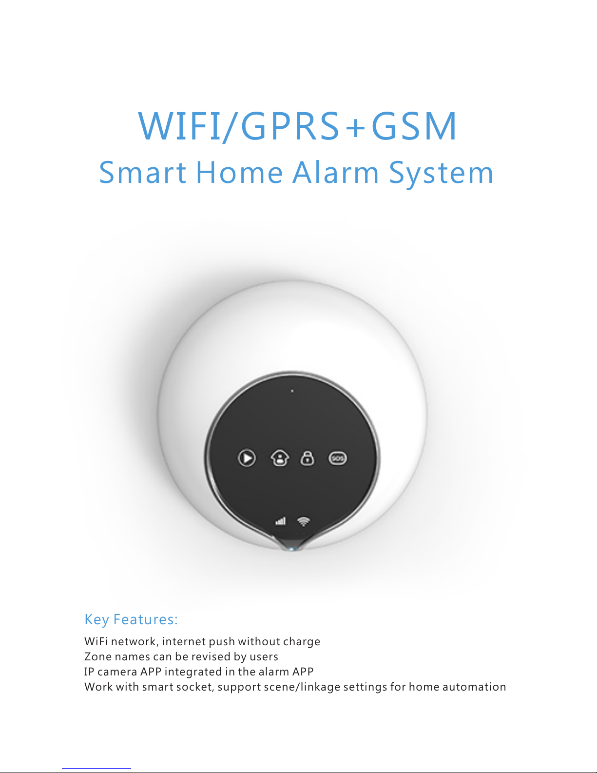
WIFI/GPRS+GSM
Smart Home Alarm System
Key Features:
WiFi network , internet push without charge
Zone names can be revised by users
IP camera APP integrated in the alarm APP
Work with smart socket, support scene/linkage settings for home automation
Page 2

Page 3

Preface
Key features
Technical information
Front side panel view
Backside panel view
Initialization
How to use APP
How to connect WiFi for host
Add equipment
Introduction of APP main interface
Sensor learning
How to learn RFID keypad
Zone attribution settings
Edit sensor attribution
Delete sensors
Host settings
Wireless relay outputs learning
The instruction for use wireless relay outputs
RF socket
RF siren
Control device
Delete device
Scene
How to add a scene
Delete scenes
Linkage
How to add a linkage
Four types linkage
Delete linkage
Histor y
IP camera monitor function
Contents
1
2
3
4
6
6
6
7
8
8
9
10
11
12
12
12
14
15
16
16
17
17
18
18
19
19
19
21
22
22
23
Page 4

Hotspot setup
Unbind equipment
Switch equipment
Authorization
Logout
Call up
Answer alarm call
Remote phone call control
Remote SMS control
Maintenance
25
26
26
27
27
28
28
28
29
30
Page 5

1
Than ks for ch oo sin g ou r GSM +W i-Fi/ GP RS /S MS ho me al ar m sys te m.
GS M+ Wi -F i/ GPRS/ SM S home al arm sy st em h as imp la nt ed the mo st
advan ce d an d popu la r Wi-Fi tec hn ol og y in to tr aditi on al GSM al ar m
sy stem tec hn ol og y, wi th v er y s imple w ireles s se t up . It ’s ver y co nv en ie nt
for use rs t o set u p th e ala rm sy st em vi a APP. C om pa red wi th tr ad it io nal
SM S AP P, Wi-F i AP P is w it h much mo re sim pl e an d qu ic ke r op er at io n.
Caution:To ensure that you can enjoy the impeccable warranty ser vice,do not
open the host-housing to repair and renovate by yourself or we will not
provide free warranty ser vice.All the losses and the adverse consequences it
makes will be assumed by users.
Preface
Page 6
2
9.Information push promptly when AC power failure/recovered or detectors in low
voltage
1.WIFI/GPRS/SMS + GSM home alarm system
When there is no WIFI, the host will work with GPRS network. If there is neither WiFi
nor GPRS network, then the alarm host will send alarm SMS and make alarm call.
Key features
Page 7

3
Power supply: AC=100 ~ 230V 50Hz/60Hz
Working voltage: DC5V 2A
Static current: < 200mA (when not under charging status)
Alarm current: < 300mA
Backup Batter y: 3.7V 1050mah
Standby time: 7 hours
Charging time: 3.5 hours
GSM frequency: 850/900/1800/1900MHz
GSM Transmission power : 2W(850MHz/900MHz);1W(1800MHz/1900MHz)
Wifi transmission Power : 1W
Receiving and emitting frequency: 433MHz (868MHz optional)
Wireless transmission distance: >100 m (Open space)
Working condition: temperature: -10ºC ~ 50ºC, humidity:5% ~ 80%
WiFi frequency:2.4G
Technical information
Page 8
SOS
4
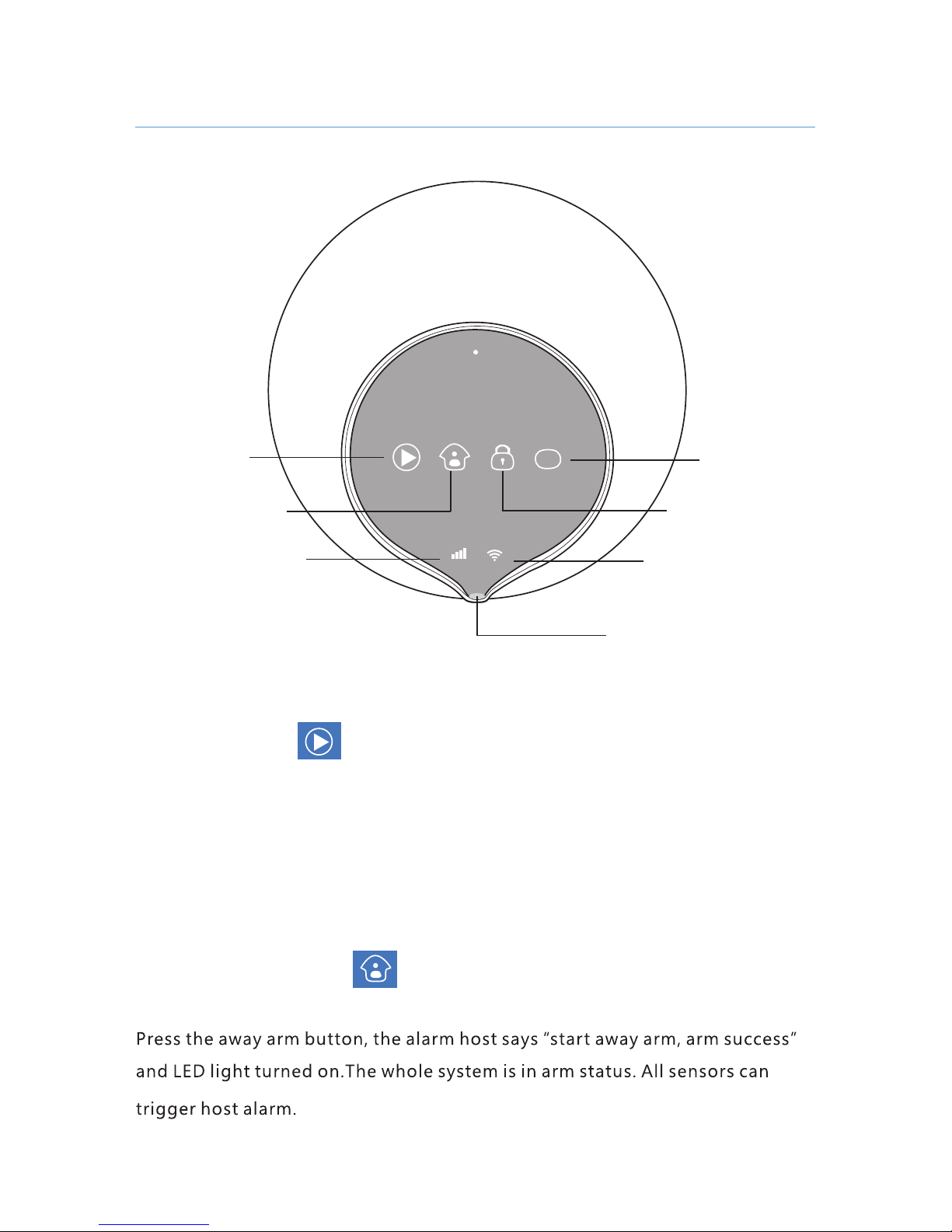
Display
Home Arm
SOS
Away Arm
GSM indicator
WIFI indicator
LED
When host receive messa ge, the display butto n w ill flash slowly, users can press the
display button to listen to t he mess age. When someone make c a ll to the host, i t will
ring and the display button f l ash fas t , user s can press th e display button to ans w e r
the call.
Display
Away Arm
Front side panel view
Page 9
5
SOS
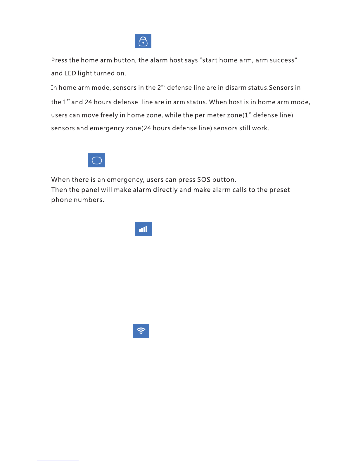
If the GSM signal do not flash, that means GSM have not initiated yet.
If the GSM signal flash once, that means GSM have initiated.
If the GSM signal flash twice, that means there is SIM card.
If the GSM signal flash thrice, that means the host can make call .
If the GSM signal keep light on, that means the host has connected to server via GPRS
network.
WiFi Signal
If the WiFi signal do not flash, that means host WiFi have not initiated yet.
If the WiFi signal flash once, that means host WiFi have initiated.
If the WiFi signal flash twice, that means the host has connected with router.
If the WiFi signal keep light on, that means the host has connected to server via WiFi
network.
Home Arm
SOS
GSM signal:
Page 10
K1K2
K1
K2
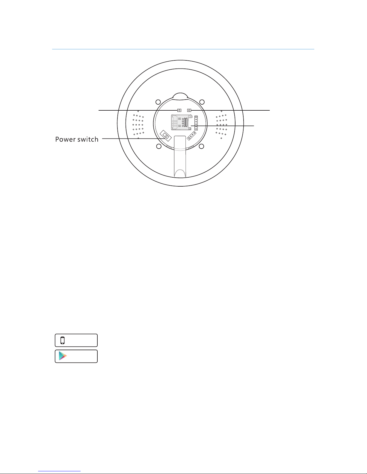
Sim card Slot
1. Af ter switch on the host, short press the K2 button to close host hotspot.
2. Af ter switch on the host, long press the K2 button to set the host to default.
3. Af ter switch on the host, short press the K1 button to open the host hotspot.
Google P la y
App Store
Avail able on t he
Initialization
Apple user search: “Carener2"
Android user search: “Carener2"
How to use App
Af ter download the APP in smartphone, user need register in APP. Click the
“Sign up free”button to go to register interface, enter phone number, email
address and password, then clink the “Confirm” button to save settings. Then
user can log in the APP.
First install SIM card and power the alarm host with adapter, then switch on
the alarm host.About 3 seconds later, the panel will make a long beep, then
initialization succeed.
Backside panel view
6
Page 11
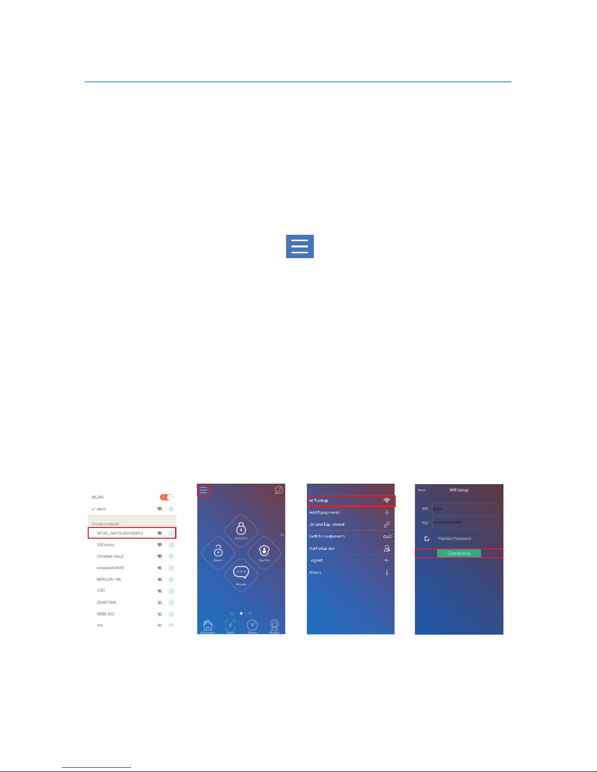
Step one: power the alarm host with adapter.
Step two: go to the WLAN interface of smartphone, find the host hotspot
whose name begin with IWTAC_.
Step four : log in APP, click the button, choose sub-menu “WiFi
Setup”,input the home WiFi name and password. And then click “Connect”
button in APP .The host will say “ star t connecting”. And if the WiFi connection
succeed, the host will say “ connect network success “ .
Note: if you can not find that hotspot, please shor t press K1 button at the
back side of host to restart WiFi for host.
Step three: Connect that hotspot. (the host hotspot default password is
123456789)
Note: the encryption mode of your router should meet one of the following:
1. WPA-PSK TKIP
2. WPA-PSK AES
3. WPA2-PSK TKIP
4. WPA2-PSK AES
5. Unencrypted (without password)
How to connect WiFi for host
7
Page 12
Away Arm: touch button to away arm the host, it will says “ start away
arm, arm success”. All sensors will be under arm status.
Home Arm: touch button to home arm the host, it will says “ start home
st
arm, arm success”. Then 1 defense line sensors and 24 hours defense line
nd
sensors will under arm status, 2 defense line sensors will under disarm
status.
Di sa rm : tou ch bu tt on to d is ar m t he ho st , i t w il l s ay s “ dis ar m
su cc es s”.
s t n d
Then th e 1 defen se li ne se nsors an d 2 defen se li ne se nsors wi ll
unde r di sa rm s ta tus , on ly 2 4 ho ur s def en se l in e senso rs u nd er a rm stat us .
Call: users can firstly set the alarm panel phone number in APP(take page 10
for reference),then press the button to make call to alarm host directly.
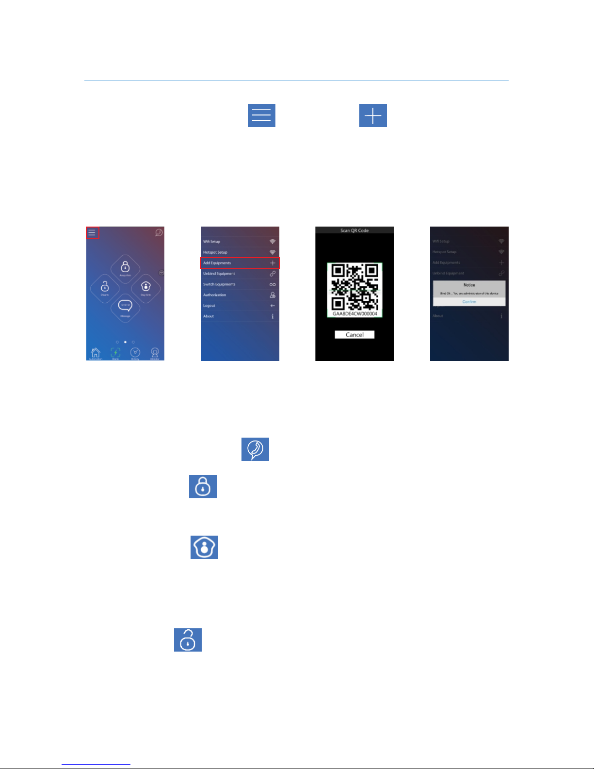
Log in APP application, click but ton,click button. Then choose
sub-menu “add equipment”, users now can scan the QR code of panel. The first
one who scan the QR code of host will become that host administrator.
Note: before users add equipment, please confirm the smartphone is connected
with workable WiFi/GPRS network but not the alarm host hotspot.
Introduction of APP main interface:
Add equipment
8
Page 13
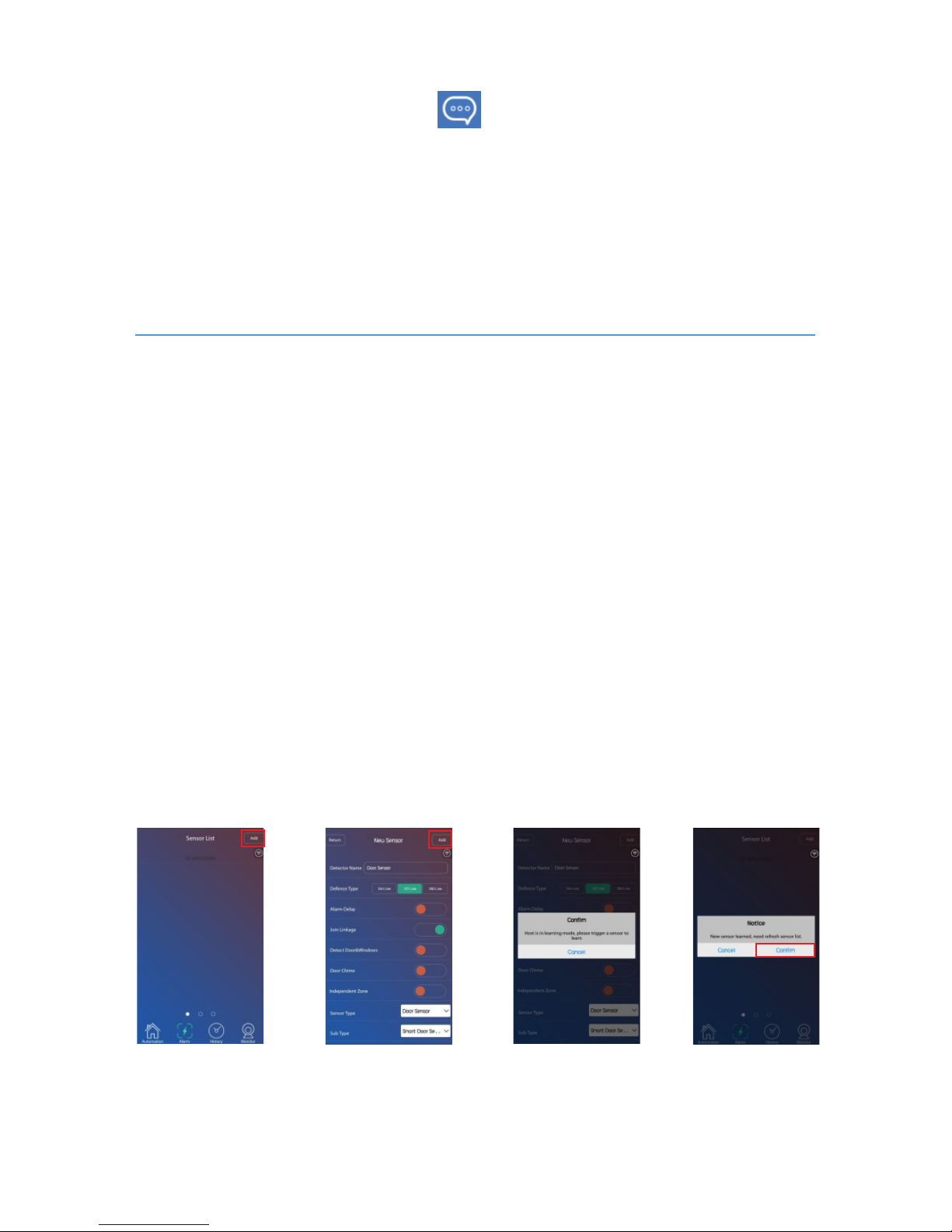
Log in APP application, slide the screen to Sensor List interface.
Step one: Click the [Add] button, the APP will go to New Sensor interface.
Step two: Input the sensor/detector name, choose defense type, and do other
functional settings, then choose Sensor Type and Sub Type. ( take user manual
Step three: click the Add button, the host will say “ start learning, please trigger
Step four: trigger the sensor.And then the host will say “ learning success”.
page 10 for reference)
detector ”
Step five: touch “Confirm” in APP when it tips “New sensor learned, need
refresh sensor list” .
Voice message : keep pressing the button and start to record the message,
release the button to end the recording. (Maximum 20s voice message can be
About 1 minute later, the display button on alarm host will flash slowly, families
members can press the display button to listen to the voice message.
recorded.)
Sensor learning
9
Page 14
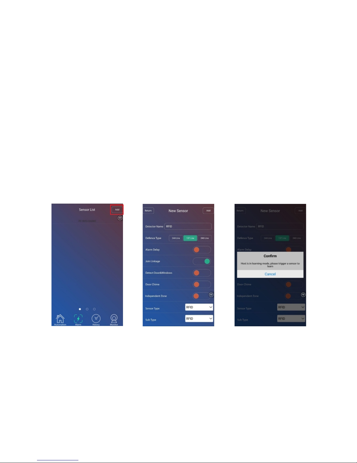
Log in APP application, slide the screen to Sensor List interface.
Step one: Click the “Add” button, the APP will go to New Sensor inter face.
How to learn RFID keypad:
Step two: choose Sensor Type as “RFID”, then click the “Add” button. The host
will say “star t learning, please trigger detector ”.
Step three : turn to keypad, press its backside tamper switch.
Once the keypad make a sound like “beep”, then coding succeed. Users can
touch“Confirm” when the APP tips “ New sensor learned, need refresh sensor
list.”
10
Page 15

Alarm delay: It is that the host will not alarm until delayed time arrives.
Note: for alarm delay time setting par t, users should take page 11 for reference.
Join link : If alarm sensor choose “join link”, then means this alarm sensor will
be active to work,if not chosen means will not work anytime in any status.
Defense Line:
24H defense line: it means 24 hours protection, the alarm sensors in this line
will trigger the alarm system whenever in arm status or disarm status, usually
panic button, smoke detector,gas leakage sensor, etc should be learned to
24H defense line.
1st defense line: it means perimeter protection, the alarm sensors in this line
will work in both away arm and home arm modes.
2nd defense line: it means interior protection, the alarm sensors in this line
will only work in away arm mode, but will be deactivated in home/stay arm
mode.
Door Chime: this function is suitable for main entrance gate installation to
remind home owners that someone is coming in when the alarm system under
home arm or disarm status.
Firstly,user need to program door sensor which want to set door chime
function in 2nd defense line.
Secondly open door chime function under the “sensor attribution” interface.
Af ter setting succeed, if alarm system is in disarm or home arm status,
somebody open the main entrance gate,alarm host will make sound like
“ding-dong”.
Detect Door : if the door/window sensors choose “detect Door ” ,then those
sensors will have smar t zone function. That is, when users away arm alarm
host the system will automatically check whether doors and windows are
closed; alarm host will remind users which door or window is open.
Note: This function is only available for two way door/window sensor.
11
Zone attribution settings:
Page 16
Sensor Type: the name of sensor
Sub Type: the type of sensor
Edit Sensor Attribution
Click each sensor and go to sensor attribution inter face. Edit each sensor
attribution and then click [save] button to save settings.
Alarm time: users can set host alarm time to 0-15 minutes.
Log in APP application, slide the screen to the right side.
Delete sensors
Independent Zone: Ever y zone can be set to be independent zone, which only
can be disarmed by APP, but can't be disarmed by remote controllers. The
feature is suitable for impor tant room or private room.
Phon e NO.: user s can inpu t the alar m host number, set the ho st
password(default:1111), and then set 6 groups alarm call numbers and 2 groups
alarm SMS numbers.
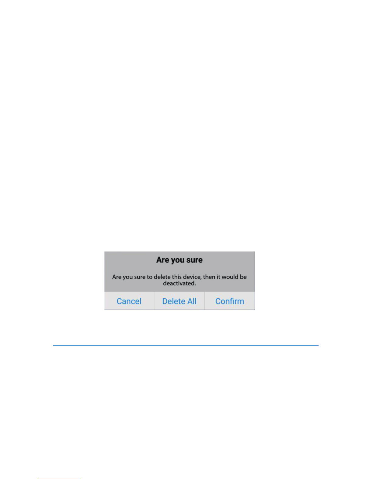
Long press each sensor, APP will tip below picture, click [confirm] to delete that
sensor, click [delete all] to delete all sensors.
Note: for smart door sensor, please choose Smart door sensor.
Note: the Sub Type can not be changed here.
Host Settings
12
Page 17

Volume: users can set Mute, Low or Loud for the panel volume.
Time Zone: connect network for alarm host, thenset time zone for host, then it
will automatically timing via internet.
Delay Set:It includes arm delay setting and alarm delay setting.
1.Arm Delay: Arm time delay setting is that the host will not be armed until
delayed time arrives. Therefore, when touch “ away arm” button on alarm
host,users will have time to deviate from house.
2.Alarm Delay: First user should active “alarm delay” function under the sub-menu
of“sensor attribution” which is mentioned in page 10. Then set time for delayed
alarm.This function is usually applied to leave time for disarm alarm host.
Ring time: the host can receive phone calls. It allow user to set the ring time from
0-90 seconds .When the ring time arrive, it will pick up the phone call for remotely
control .Users can take page 25 for reference of remote phone call control.
Auto Arm: this is the auto arm/disarm function. In total user can set three groups
auto arm/disarm time . For each group, user can set the arm time and disarm time,
choose the date from Monday to Sunday, then click the “activate” button to
activate that group time setting. Finally click the “save” button to save all settings.
Push alert: This Function is for setting AC fail and recover alert, Arm/Disarm alert,
alarm host battery low voltage alert, Sensor low battery alert, Wi-Fi ok or
disconnect alert , door open or close alerts.
SMS push: when the host do not connect with WiFi or GPRS, it will work with
GSM+SMS. If users activate the SMS push function, then users who is set to be
alarm SMS number[user manual page ** phone NO.] can receive SMS alerts of AC
fail and recover, Arm/Disarm, alarm host battery low voltage, Sensor low battery
,Wi-Fi ok or disconnect, door open or close.
Language: set language for host.
Note: it will take 30s-120s to switch language for host, because the host need
time to download the language file from server and install the new language
program.
13
Page 18
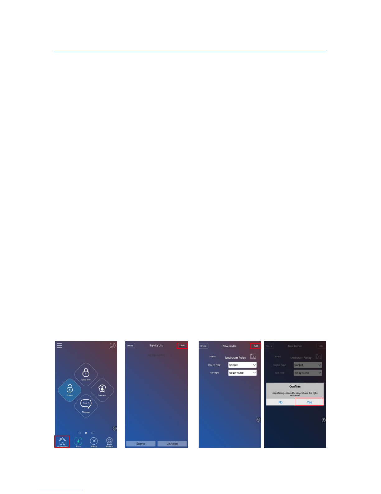
Four thly, press the learning button of relay, the indicator light of relay will flash
and .relay make switch sounds
Sixthly, disconnect power adapter from relay. And then reconnect power
adapter for relay. Then users can control relay outputs on APP.
Fif thly, users can click Yes button of the APP notice “Registering, does the
device have the right action ?” The APP will refresh the device list. And the
host will say “ learning success” .
Thirdly, Input device name, choose Device Type “ ” and choose Sub Type socket
“ ”. Then click the Add button. The host will say “start learning, Relay-4Line
please trigger detector ”.
Fi
rstly, Connect wireless relay outputs with power adapter. To reset the relay,
user can long press its learning button about 6 seconds until the LED indicator
lamp lights on again.
Secondly, log in APP application, click the “Automation” button to enter the
device List interface. Then click the Add button to go to New Device adding
interface.
Wireless relay outputs learning
14
Page 19
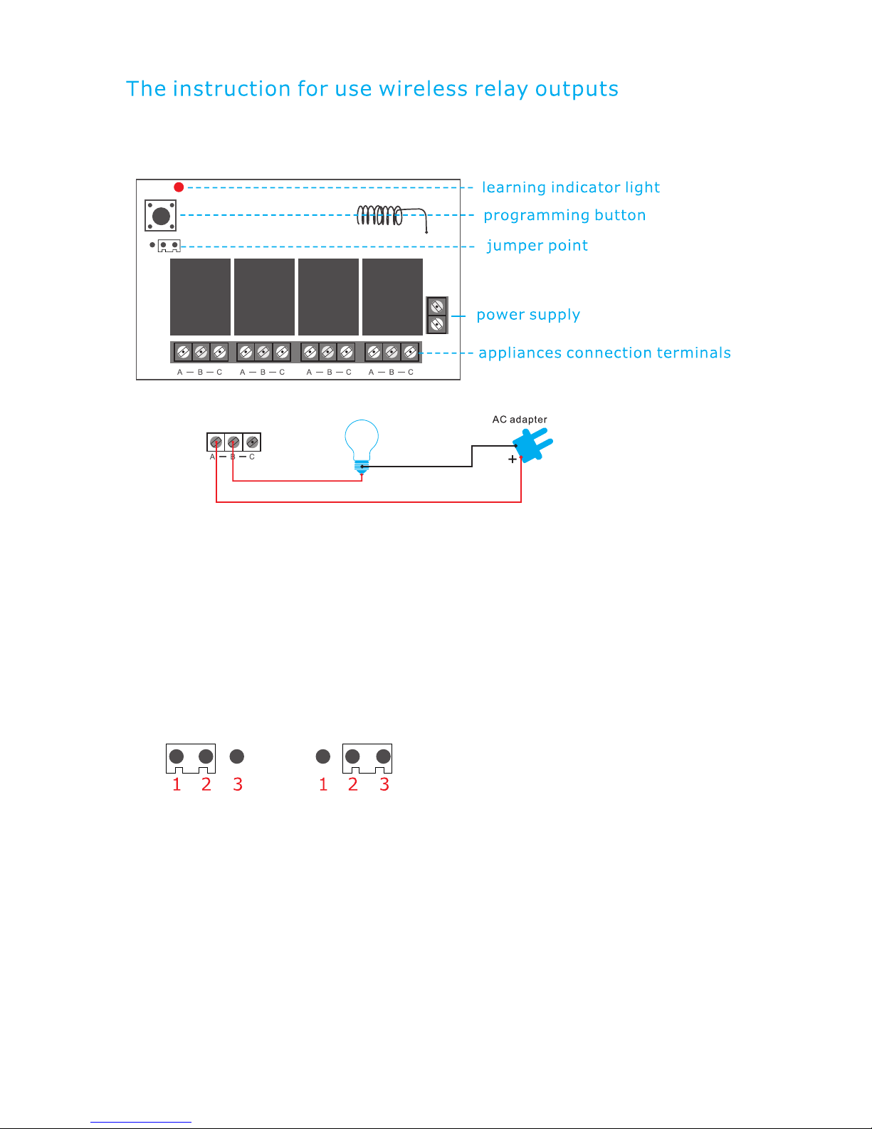
Attention:
When you plug the Jumper between the 1, 2 pins, four bulbs will
simultaneously be opened and closed, or opened /closed several of them;
when Jumper between the 2, 3 pins, you can only turn on one bulb once, for
example, if you have already opened the '1' bulb, when open the “2”
bulb,the'1' bulb will go off.
There are four groups of "A/B/C" in a relay and one group will control one set
of circuit. As known to all that only a closed circuit formed the appliance
works, that's to say the relay is a switch in this circuit. For example: If you
would like the beside lamp controlled by the first group, simply cut off the Fire
Wire of bedside lamp circuit and reconnect the two sides of A B. Of course, you
can also be cut off the zero line to plug in A and B of the first group as well.
Same goes for the second, third and four th group.
15
Page 20
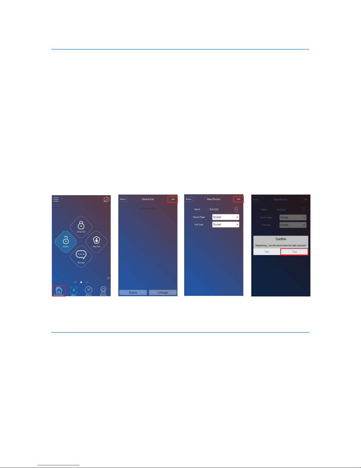
Firstly, log in APP application, click the “Automation” button to enter the
Device List interface. Then click the Add button to go to New Device adding
interface.
Secondly, input device name, choose Device Type “ ” and choose Sub Socket
Type “ ”.Then click the Add button. The host will say “start learning, Socket
please trigger detector ”.
Thirdly, keep press the learning button of RF socket about 3 seconds and then
release, the indicator light of socket will flash and the socket will make switch
sounds.
Four thly, users can click Yes button of the APP notice “Registering, does the
device have the right action ?” The APP will refresh the device list. And the host
will say “ learning success” .
Fi r s tly, log in APP application, c l ick the “Automation” button to enter the D e vice List
in t erface. Then click the Add butto n t o go to New Device adding interface.
Secondly, input device name, choose Device Type “Siren” . Then click the Add
button. The host will say “start learning, please trigger detector”.
Thirdly, long press outdoor siren learning button for 3s or short press indoor siren
learning button to and start coding with alarm make sirens under learning status
host.
RF Socket
RF siren
16
Page 21
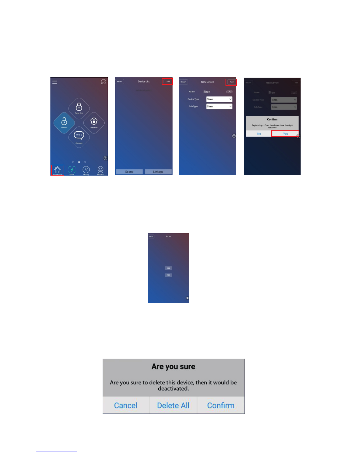
Fourthly, users can click Yes button of the APP notice “Registering, does the device
have the right action ?” The APP will refresh the device list. And the host will say “
learning success” .
Delete devices
Click that device(siren/relay output/smart socket), APP will turn to device
control interface. then users can turn on/off devices.
Control devices:
Long press device , the APP tips below, users can click [confirm] to delete that
device, click [delete all] to delete all devices.
17
Page 22
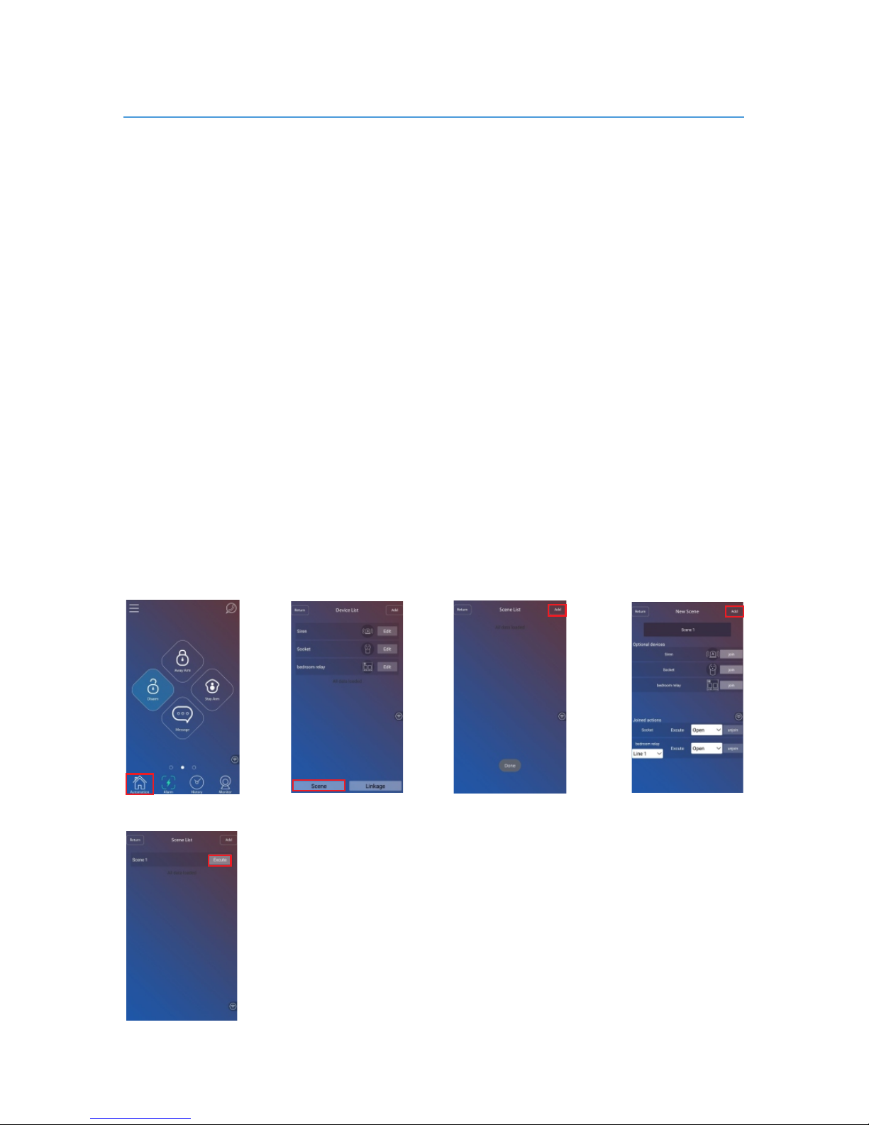
Sc e n e is a serial of devices actions.
For example, users can se t a return home scene. When users the scene, theExecute
li v ing room light and the air-condition will be turned on.
How to add a scene
Fi r stly, Log in AP P application, click th e “Au t omation” button to en ter the Device List
in terface. Click the “Scene” button to en t er Sce n e Lis t inte r face. Then click the Add
bu tton to enter New Scene adding i n terface.
Se c o ndly, enter the new sc e ne name, join devices in option a l devices list.
No t e: Devices can be joined one or more times.
Th i rdly, set open/close actions for each j oined devices. If do not need that device, just
un j oin it.
Fourthly, After finish all settings, click the A dd button t o save thi s new scene. The new
sc e ne will list in the S c e ne List interface. Then users can click button to “E x e c ute”
execute that scene.
Scene
18
Page 23
What is linkage: a trigger which can be detector or time make one device or
one scene act. That is:
when a sensor is triggered, the linked device and scene will act
When it arrives the set time, the linked device will act
When a sensor is triggered, the linked scene will act
When it arrives the set time, the linked scene will act
For example:
When the front door open, the front door lamp will be turned on.
When it is 8am, the bedroom light will be turned on.
When the front door open, the scene(the front door lamp turn on and the
air-condition turn on) will act.
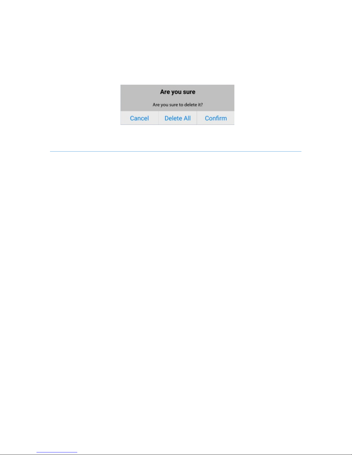
Delete scenes
Lo n g press scene , APP tips below, u ses can click [confirm] to d e lete tha t scene, click
[d e lete all] to delete all scenes.
Firstly, Log in APP application, click the “Automation” button to enter the
Device List interface. Click the “linkage” button to enter linkage/If-then list
interface. Then click the “Add “button to enter New linkage adding interface.
How to add a linkage
When it is 8am, the scene(the bedroom lamp turn on and the cur tain open)
will act.
Linkage
19
Page 24
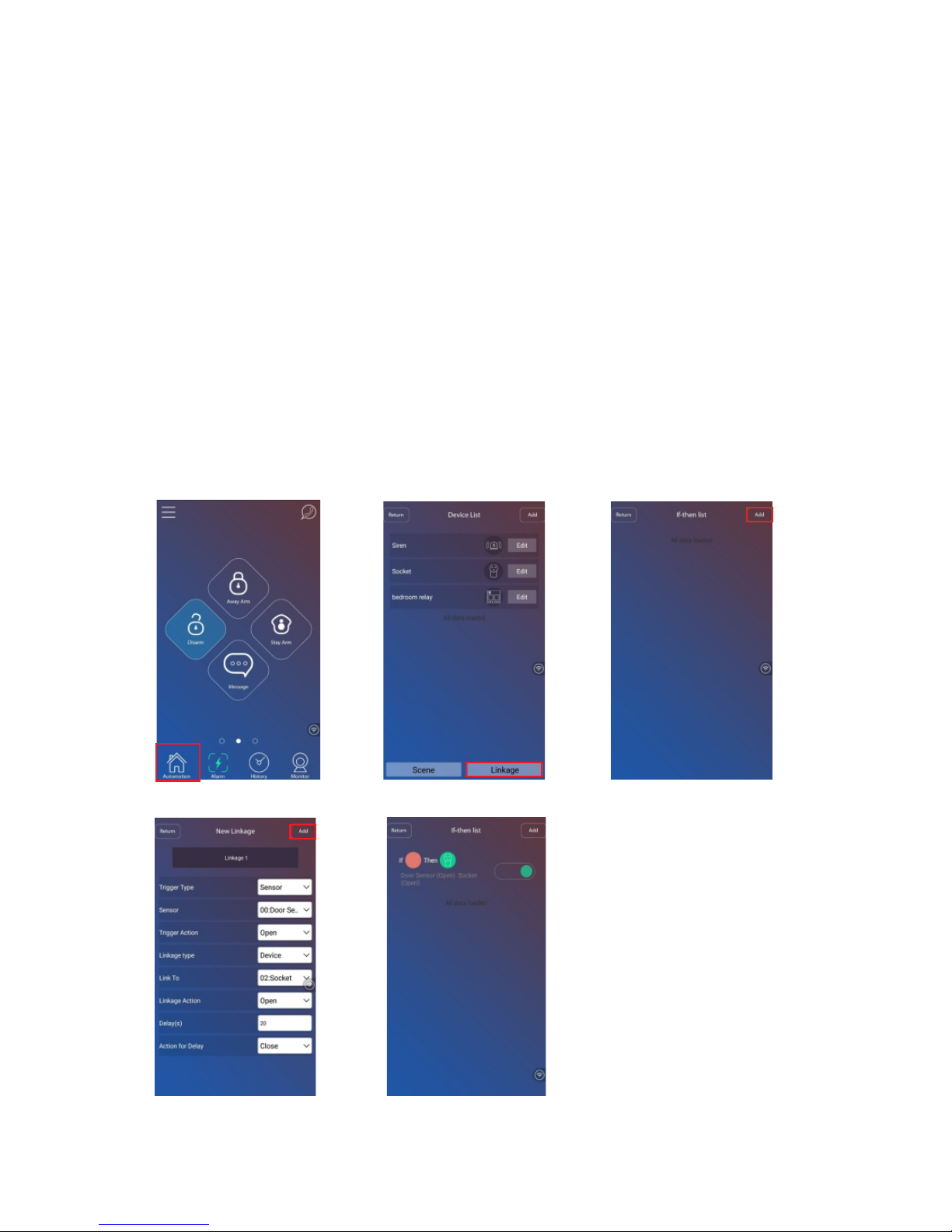
Firstly edit new linkage name.
Trigger Type can be sensor or time.
Trigger action can be close or open.
Linkage type can be device or scene.
Linkage Action can be open or close
Delay Action for delayand : if the linked one is device, users can also set a
delayed action for that device. That is, a trigger which can be detector or time
make one device act, after some delay time, the device can do another action.
For example:
When the front door open, the front door lamp will be turned on. After 30
seconds, the front door lamp will be turned off.
When it is 8am, the bedroom light will be turned on. After 2 minutes, the
bedroom lamp will be turned off.
20
Page 25
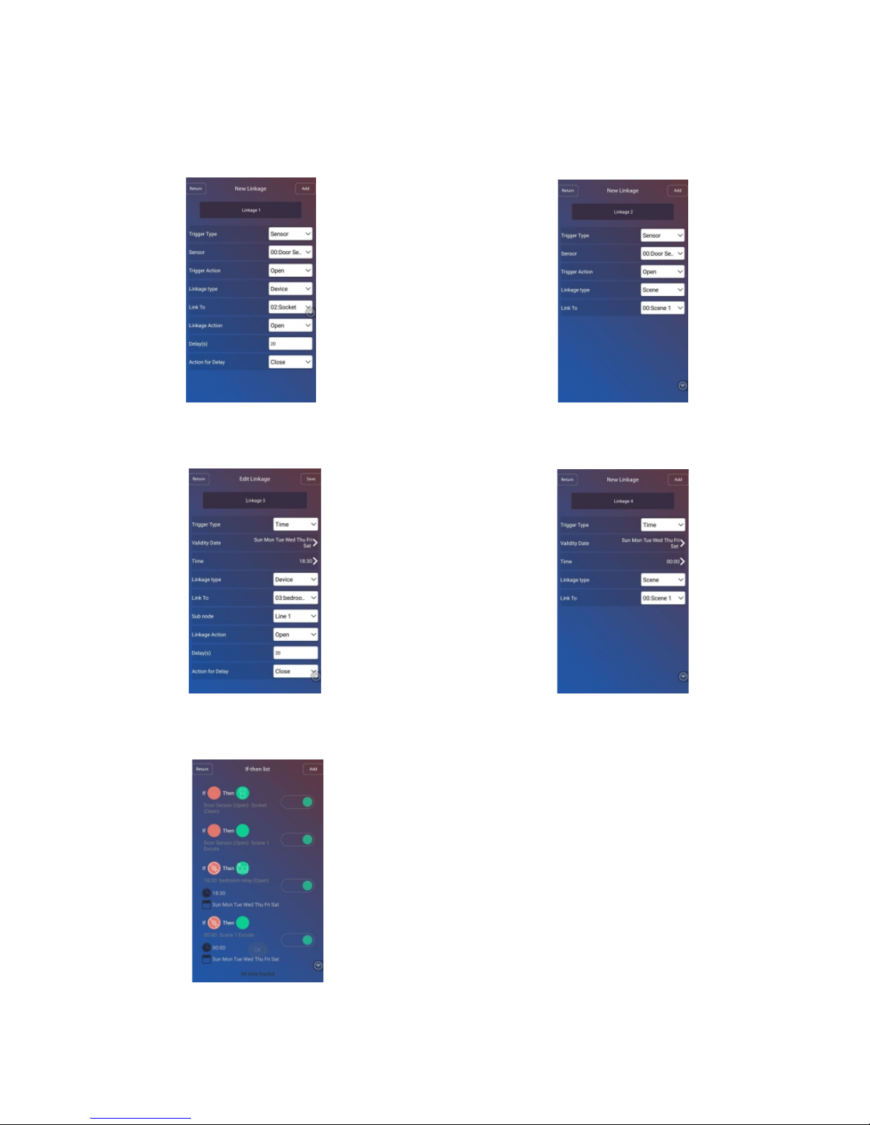
3. Time linked to device
4. Time linked to scene
Four types linkage:
1. Sensor linked to device
2. Sensor linked to scene
21
Page 26
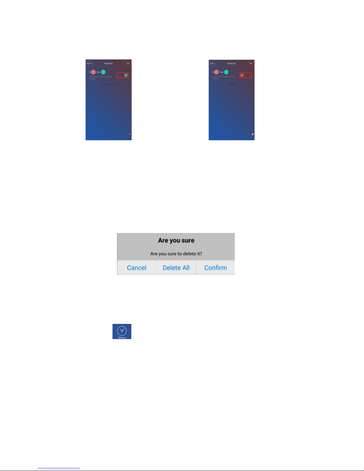
Delete linkages
Enable and Disable linkage:
Long press linkage , APP tips below, uses canclick [confirm] to delete that
linkage, click [delete all] to delete all linkages.
History
Click the [histor y] button, the latest 100 alarm and operation records can be traced.
22
Page 27

To better experience the convenience of this product, before using this product,
please download the Phone App.
Install IP camera APP in smart phone and register.
Smartlink: users need to power on IP camera with adapter. Choose “smartlink”
to enter next inter face, click “Next” to enter next interface ,then fill in the WiFi
password and click “Next”.Wait for some time until the APP shows IP camera ID,
input the device password(default:123) and click “save” button, then adding
succeed.
Manual Add: Firstly, choose “manually” to enter “Add device” inter face.
IOS users can go to the APP Store to search ” ” and download IP camera yoosee
App.
Android users can go to the Google Play to search “ ” or visit the yoosee
website ( ) to download the IP camera APP.www.yoosee.co
Note: after adding succeed, if there is exclamator y mark beside the device,
users should change more complex password for IP camera.
Enter alarm panel APP interface, press button to enter IP camera “Device
List”interface, press button on the top right corner, users will see two
ways to add IP camera ,that is“smartlink” and “manual Add”.
Secondly :enter IP camera ID , input device name and input device password.
Press to finish adding.
Note: IP camera ID is at the bottom sticker of IP camera. Users can define device
name and default device password is 123.
IP camera monitor function
23
Page 28
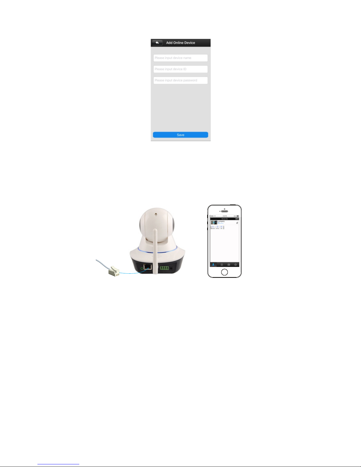
Thirdly: Power on the IP camera and then connect IP camera with network cable.
Then the IP camera can connect with network . Refresh “Device list” , then users
can see that IP camera would be “online”.
Four thly, Click that IP camera device, appear “playback”, “setting” and “edit”
buttons. Choose “Setting” to enter below interface.
Sixthly: Choose the available WiFi in the list, enter password, and press OK
button to finish setting.
Fif thly:Choose”Network Settings”to enter below interface.
Finally: Then device can work with WiFi network and users can pull up the
network cable. Then press next step to finish installation. After installation,
Once IP camera is online (connect Power and Wi-Fi/wired internet), user can
check what is happening in his house anytime and anywhere.
24
Page 29
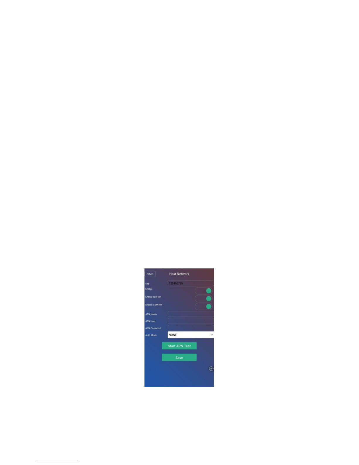
Hotspot setup
Key: the alarm host hotspot password (default:123456789), users can edit the
password.
Enable: users can enable/disable the host hotspot
Enable WiFi Net: users can enable/disable WiFi network of alarm hosts.
Enable GSM Net: users can enable/disable GSM network of alarm host.
About APN:
Install SIM card and then turn on the alarm host, connect WiFi for host, the
host will configure APN automatically and the APP will shows the APN name.
Note: the alarm host will automatically configure APN only when users change
SIM card for host or reset host.
If the host still can not work with GPRS network of the recommended APN.
Then users need manually configure APN information. Users can know APN
information from SIM card operator. Then turn to the APP APN setting: input
APN name, APN user and APN password, and click Save button. Finally user
need restar t alarm host to make it configure new APN.
25
Page 30
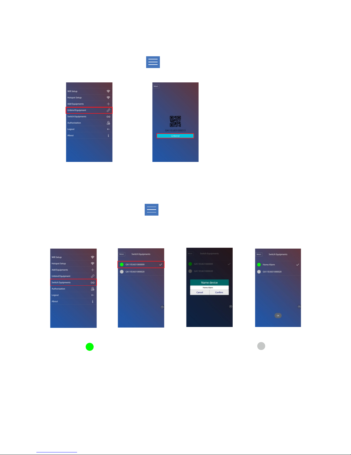
Switch equipment
Log in APP application, click button. Then choose sub-menu
“switch equipment”, popping the below picture, touch each device to switch
equipment.
1.The icon turns green, means this device is online;if the icon turns gray,
means this device is off line. For example in picture 1 device name
GA11EU631000009 is online and GA11EU631000020 is off line.
2.Long press device name to revise device name. it will pop-up the [Name
device] dialog box ,input the new device name in dialog box, touch Confirm
button. After appear the tip“OK”,then modify device name succeed.
Unbind equipment
Log in APP application, click button. Then choose sub-menu “unbind
equipment”, user can touch “Unbind” to unbind the present equipment.
26
Page 31
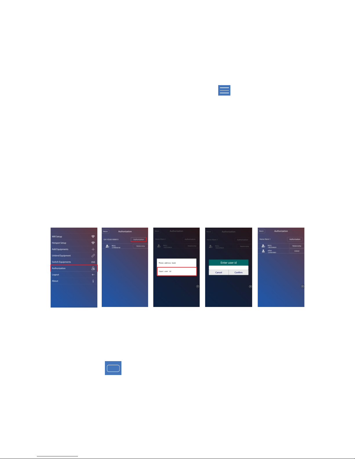
Authorization
After authorization, the authorized users can control the host and receive pushes .
The authorized user can not authorize other users. Only the administrator can
authorize other users,and administrator can also unbind the authorization.
The default administrator name is “NULL”, users can press the “Relationship”
button and then revise administrator name.
The APP administrator can give authorization to other users. The other users
need to download APP and sign up firstly and get the right to be authorized,
then the administrator can successfully give authorization.
Operation as below: log in APP application, click button. Then choose
sub-menu ”A uth ori zat ion ”. Click “Auth orization” butto n, For And roid
smar tphone, users can choose “Phone address book” and “Input user ID” to
authorize other User ID is the account of other user who need to be
authorized..
Logout
User can touch button to return to log in page.
Log out
27
Page 32

Call up
Answer alarm call
Press [1]: the host stops alarming to Away Arm; it stops calling other users.
Press [2]: the host stops alarming to Home Arm; it stops calling other users.
Press [3]: the host stops alarming to Disarm; it stops calling other users.
When th e alarm host make alarm . Firstly it will send alarm push/SMS to
smar tphon e. The n it will di al the preset numbe rs. If no one answers the cal l,
the host will call the next number automati cally. I f you answer the cal l, you
will hear the vo ice like “ di ”. You can set the host vi a your smar tphone
keypad.
It means alarm host can be used as a ha nd-free phone: when someone make
call to alarm host, the host will ring and the per son b eside the a larm host c an
touch the “displ ay” button to answer the call . Af ter finish con versation touch
the “display” button again to end the c all.
Press [5]: start talkback.
Note: if you press [3] to disarm, the phone call will stop and you can not do other
operation. For other operations, you can do more operations and then hang up
the call.
Press [4]: the siren will stop ring and the host will start monitor.
Remote phone call control:
User can use telep hone to make a call to remote con trol panel. After the ri ng,
user will hear the rapid vo ice like “ di di di di”. Then users can input user
pa ssword( ) and then press “ #” to confirm. For Default user password is 1111
wrong password, users will hear the voice like “ di di”. For correct pass word,
users will h ear the voice like “di ”, and then users can set the host via
smar tphon e keypad.
28
Page 33

Press [1]: the host stops alarming to Away Arm; it stops calling users.
Press [2]: the host stops alarming to Home Arm; it stops calling users.
Press [3]: the host stops alarming to Disarm; it stops calling users.
Press [4]: the siren will stop ring and the host will start monitor.
Press [5]: start talkback.
Note: if you press [3] to disarm, the phone call will stop and you can not do other
operation. For other operations, you can do more operations and then hang up
the call.
Remote SMS control
Disarm : #+user password+disarm+#
When the host do not connected with WiFi, it will work with GSM/SMS. SMS
control operation and corresponding SMS as below:
Away Arm : #+user password+away arm+#
Home Arm: #+user password+home arm+#
Check Status : #+user password+inquir y#
For example: The alarm host default user password is 1111. Users can send
SMS “#1111disarm ” to disarm host. If the operation succeed, the host will #
feedback a SMS “ System Disarmed,Device:XXXXXXXX”.
29
Page 34

Manually trigger detectors to check whether they trigger panel alarm.
Check batteries of all detectors to see whether they are under voltage.
Whether the host normally dials up the telephone numbers.
Whether the host can receive detector signal and whether its backup battery
works.
Notice
Alarm equipment, for explosion-proof design, shall not directly be used in
Do not dismantle, repair and modify products privately. Without permit and
consent from relevant department, do not directly set "110", "119" or alarm
phone number of police stationas as alarm phone number of the host.
hazardous location.
Maintenance
Alarm system need regular care and maintenance and detection to ensure they
work stably and securely. Normally the host needs a thorough inspection every
3 months and the detectors need to be checked once a month.
!
!
!
!
30
Page 35

Page 36

t
c
u
d
o
r
P
n
e
r
e
G
Ro H S
 Loading...