

DT SWISS R 535 ONE Technical Manual

R 535 ONE
TECHNICAL MANUAL
V2019.08

1. GENERAL ...........................................................................................3
2. DESCRIPTION ....................................................................................6
3. OPERATION AND SETTING ...............................................................13
4. SERVICE AND CARE ..........................................................................18
5. REPLACING THE SPHERICAL BEARING ..........................................28
6. TROUBLE SHOOTING ........................................................................30
2
1. GENERAL
1.1 VALIDITY
This manual describes the component specied on the front page and the footer. It is valid for the technical
condition of the component at the Sep. 02, 2019. Design changes remain reserved.
1.2 SAFETY
The safety instructions are classied as follows:
DANGER
...indicates a hazardous situation that, if not avoided, will result in death or serious injury.
CAUTION
… indicates a hazard with a medium level of risk which, if not avoided, may result in minor or moderate
injury.
NOTE
… indicates a potentially hazardous situation that may result in damage to property.
1.3 TARGET GROUP
This manual is only intended for DT Swiss service centers. The works described in this manual may only be
done by skilled professionals trained by DT Swiss. If you have any doubts about your own abilities, you should
denitely contact a specialist or a DT Swiss Service Center.
If the work is not carried out properly, any warranty claims expire.
1.4 USING THIS MANUAL
The steps described in this manual must be carried out in the order they are shown. If steps are ignored or
executed in a wrong order, the function of the component cannot be guaranteed.
Instructions begin with the table «Preparatory Steps» and end with the table «Closing Steps». The instructions
in these tables must be carried out.
3

1.5 GENERAL MAINTENANCE INFORMATION
Unless otherwise specied, O-rings and seals must be greased before assembly.
CLEANING
For an optimal result of the maintenance works, every component that will be disassembled must be cleaned.
Only use cleaners which do not damage the components. Especially the cleaning of O-rings and sealings
requires mild cleaners. Observe the instructions for use of the respective cleaning agent.
DT Swiss recommends the following cleaning products:
• Motorex Rex
• Motorex Swissclean
• Motorex OPAL 2400, 3000 OPAL, OPAL 5000
Use soap water or similar mild cleaners for external cleaning.
TOOLS
To ensure a damage-free mounting and dismounting of the components, only use the tools which are
mentioned in this manual. Special tools are indicated at the beginning of a chapter in the table "Required
material".
The use of different tools is at the discretion of the user. If components are damaged by the usage of differing
tools, the user is liable.
DT Swiss special tools are precision tools. Damage-free mounting and dismounting of the components can
only be ensured if the tools are working properly and if the conditions of the tools are perfect Always keep the
tools in their original packaging or adequate devices to save them from damages.
R 535 ONE Technical Manual - GENERAL4

1.6 ENVIRONMENTAL PROTECTION
The statutory regulations shall apply. Whenever possible, avoid creating waste. Waste, especially carbon,
lubricants, cleaners and any other uids must be disposed in an environmentally compatible manner.
Only print this manual if electronic usage is not possible.
1.7 EXCLUSION OF LIABILITY
The activities listed in this manual may only be carried out by persons with sufcient specialist knowledge.
The user is liable for any damage or consequential damage caused by wrong maintained or wrong installed
components. If you have doubts, please contact your allocated DT Swiss pro level service center.
1.8 WARRANTY (EUROPE)
In addition to the general guarantee required by law, DT Swiss AG based in Biel/Switzerland, provides a
guarantee for 24 months from the date of purchase. DT Swiss AG shall reject any liability for both indirect
damage caused by accidents and consequential damage.
Any contradictory or extended national rights of the purchaser are not affected by this warranty. Place of
performance and jurisdiction is Biel/Switzerland. Swiss law shall apply.
Submit any warranty claims to your retailer or a DT Swiss service center. Any defects recognized by DT Swiss
AG as a warranty claim will be repaired or replaced by a DT Swiss service center.
Warranty and guarantee claims can only be made by the original purchaser with a valid sales receipt.
There shall be no claim under the guarantee for:
• Normal wear and tear caused by use of the components
• Incorrect assembly
• Incorrect or nonexistent maintenance
• Incorrectly completed repairs
• Use of unsuitable products
• Modication of components
• Incorrect use or misuse
• Carelessness
• Leasing, commercial use or use in competitions
• Damage caused by accidents
• Delivery and transport damage
• Modication, defacing or removal of the serial number
5

2. DESCRIPTION
2.1 SPRING
2.1.1 SAB (SMOOTH AUTO BALANCING)
POSITIVE
NEGATIVE
The SAB (Smooth Auto Balancing) system only consists of a bypass located in the air chamber. The bypass
ensures that the pressure inside the negative air chamber is higher than in the positive air chamber when the
shock is fully extended. This reduces the force of the beginning stroke. The shock responds very smooth and
offers more comfort and traction.
Function in detail, see following.
R 535 ONE Technical Manual - DESCRIPTION6
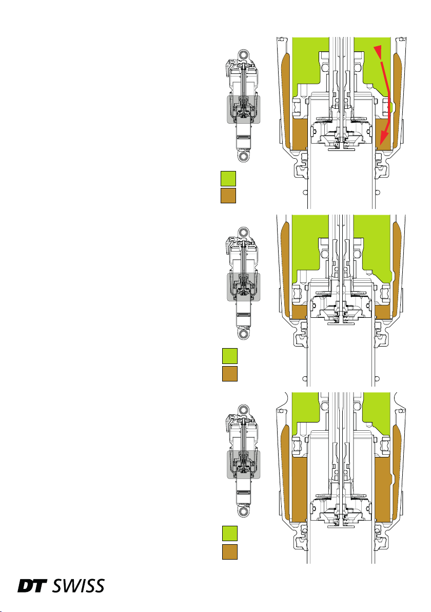
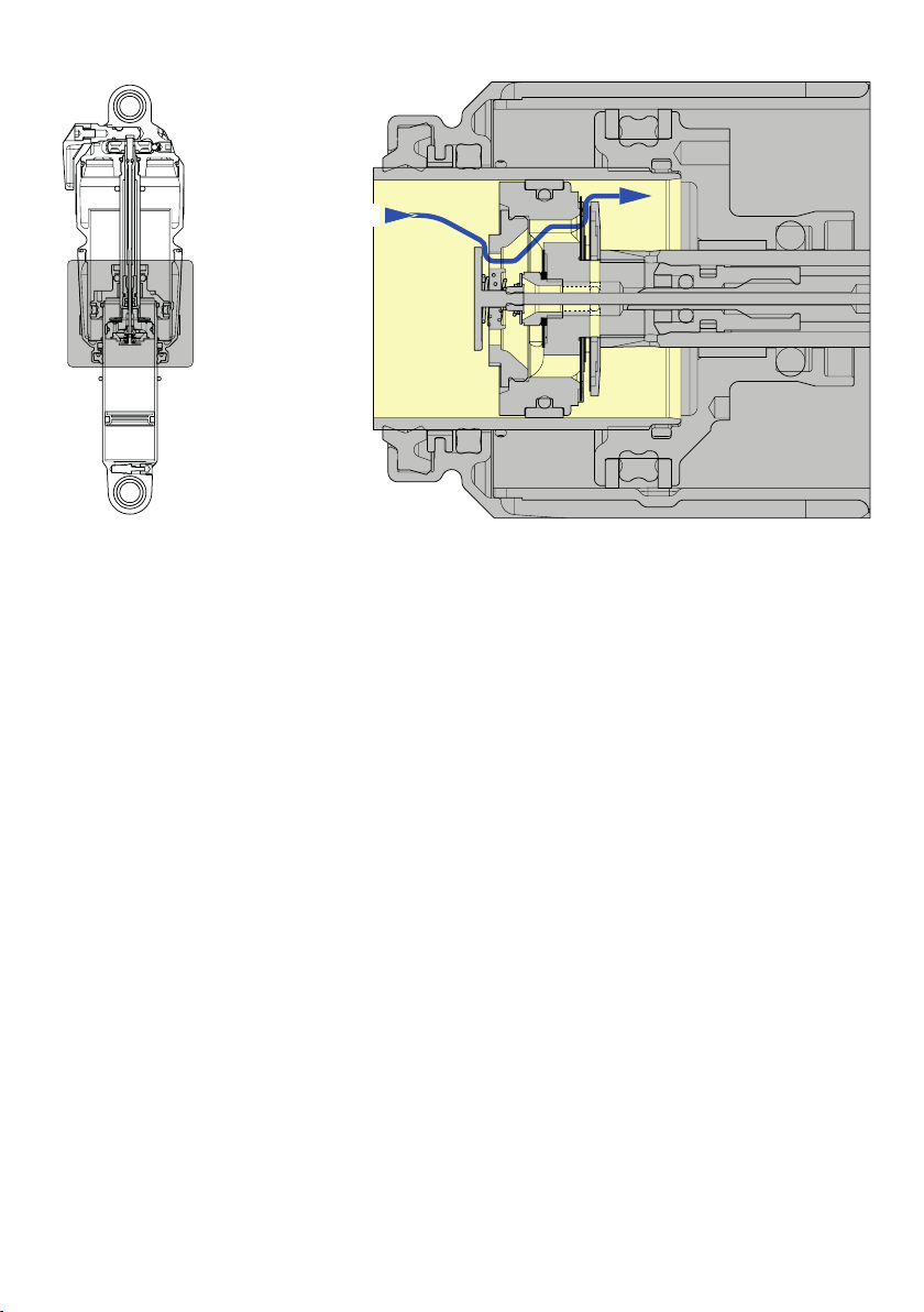
FUNCTION IN DETAIL
After inating or changing the air pressure:
When the shock compresses, the piston moves over
the bypass of the air chamber. When the piston is
located on the bypass, the bypass ensures a pressure
equalization of the positive and negative air chamber
(see red arrow).
Function during operation:
Due to the pressure equalization, the pressure in the
negative air chamber is higher than in the positive air
chamber when the shock is fully extended.
This increased pressure inside the negative air
chamber counteracts to the breakaway torque and
improves the response characteristics drastically.
POSITIVE
NEGATIVE
When the shock is compressed further, only the air
inside the positive air chamber is compressed.
When the shock extends again, a pressure builds up in
the negative air chamber and the cycles starts again.
POSITIVE
NEGATIVE
POSITIVE
NEGATIVE
7
2.2 DAMPING
The shock is a closed system. The damping oil is kept under pressure by a prestressed internal oating
piston (IFP) even in the rest position. This prevents the oil from foaming and ensures a constant damping
performance even on long, rough downhills.
The oil touches the inside of the oil chamber over the entire area, enabling optimum heat dissipation.
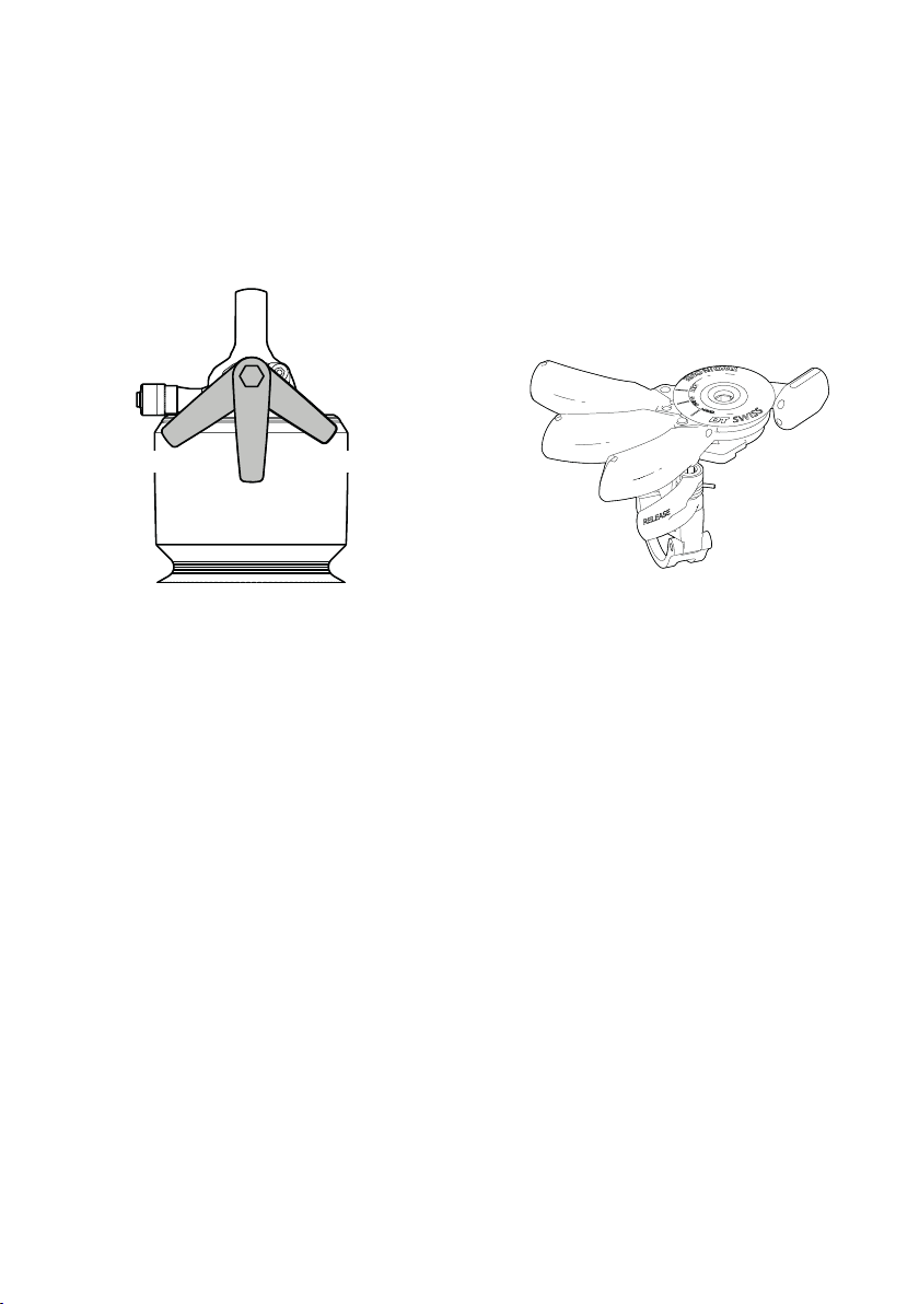
2.2.1 COMPRESSION
The compression damping regulates the compression speed of the shock and can be adjusted in three stages
via the lever on the shock or using the remote lever on the handlebars.
LOCK
LOCK
OPEN
DRIVE
DRIVE
OPEN
OPEN
In “OPEN” mode, the compression of the shock is in the most sensitive, factory-set setting. The shock
responds sensitively to small unevennesses in the terrain.
The ne tuning of the low and high speed compression is factory set and cannot be changed.
Detailed description, see chap. „Function in detail: OPEN Mode“ on page 9.
DRIVE
If the lever on the shock or remote lever on the handlebars is moved to the middle position, the compression
damping is partially closed. This makes the bike much more rm and encourages effective pedalling in
situations where the full performance of the shock is not required (uphill climbing on roads or easy trails,
rides on level ground).
Detailed description, see chap. „Function in detail: DRIVE Mode“ on page 10.
LOCK
The «LOCK» mode blocks the shock in fully extended position. This is mostly suitable for situations where no
suspension is needed (for example riding on the road or connecting trails).
A blow-off valve protects rider and material from unexpected hits.
Detailed description, see chap. „Function in detail: LOCK Mode / Blow Off“ on page 11.
R 535 ONE Technical Manual - DESCRIPTION8
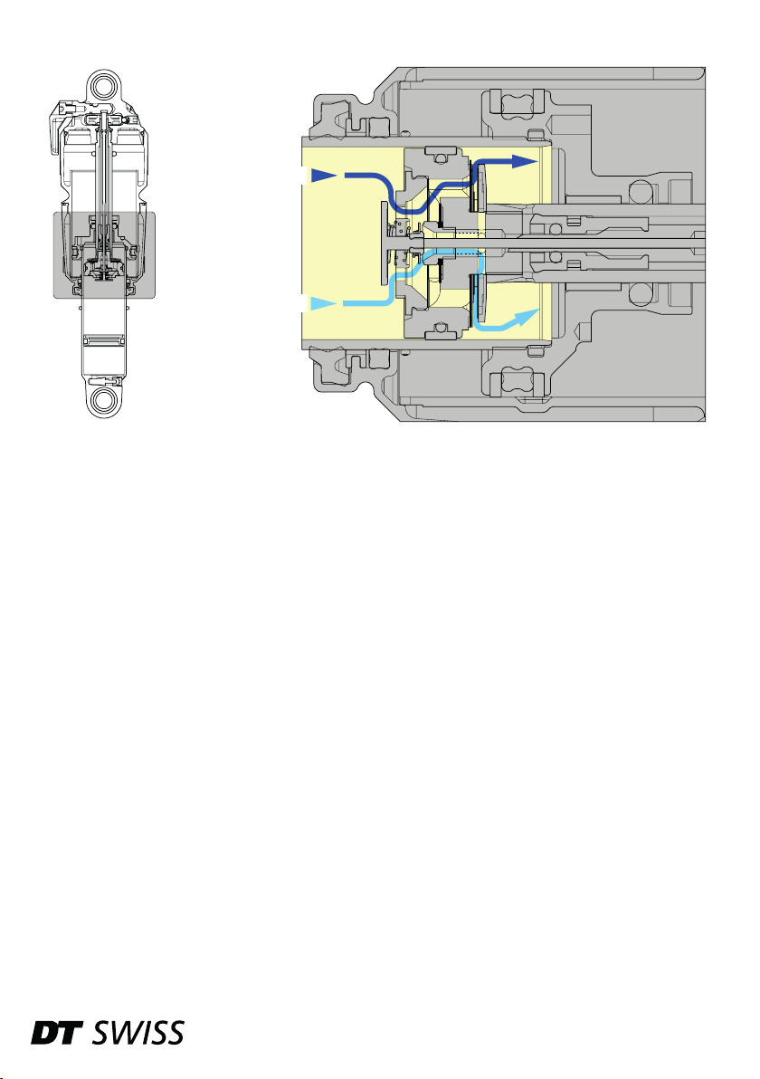
FUNCTION IN DETAIL: OPEN MODE
HSC
LSC
When the shock compresses, the damping piston moves through the oil chamber. The oil ows through the
damping piston. During slow compression movements, the oil ows through the low speed compression (LSC)
channel. The oil ow is regulated by shims. Depending on the "factory setting", these shims are differently
hard and thus inuence the damping curve.
In the case of rapid compression movements, the oil also ows through the oil channel of the high speed
compression (HSC). Before the oil can ow into the rebound chamber, it must rst overcome the force exerted
by the shims. Depending on the "factory setting", these shims are differently hard and thus inuence the
damping curve.
Due to the piston rod, the volume of the oil chamber is different on both sides of the damping piston. More
oil is displaced than can be absorbed behind the piston. This excess oil compresses a chamber lled with
nitrogen, which is separated from the damping oil by an internal oating piston (IFP).
9
FUNCTION IN DETAIL: DRIVE MODE
DRIVE (HSC)
If the DRIVE mode is activated, a slider blocks the oil channel of the low speed compression (LSC). The
displaced oil can only ow through the oil channel of the high speed compression (HSC).
R 535 ONE Technical Manual - DESCRIPTION10
 Loading...