

Startup Manual
DTS INSIGHT CORPORATION
Startup Manual
No. M2380AN-05
Publication History
Edition Date of Issue Description
1st Edition December 4, 2005 Initial publication
2nd Edition December 13, 2005 Description is modified.
3rd Edition August 16, 2006 Description is modified.
4th Edition March 10, 2014 URL description is modified.
5th Edition March 20, 2014 Description for NETIMPRESS next is added.
(1) No part of this manual may be reproduced or transmitted in any form or by any means,
electronic or mechanical, without the written permission of DTS INSIGHT
CORPORATION.
(2) The contents of this manual are subject to change without prior notice due to
improvement of the functionality.
(3) If any question about the contents of this manual arises, contact DTS INSIGHT
CORPORATION.
(4) DTS INSIGHT CORPORATION shall not be held responsible for direct or indirect
adverse effects resulting from operation of this system irrespective of the above item
(3).
Product and company names mentioned in this manual are the trademarks of their
respective owners.
© 2014 DTS INSIGHT CORPORATION. All rights reserved
Printed in Japan
I

Contents
1
Overview & Features ..................................................................................... 1
2
Notes & Points ............................................................................................... 2
3
Checking Hardware and Software (Standard Package) ............................. 3
3.1 Hardware .................................................................................................................... 3
3.2 Software ..................................................................................................................... 4
4
Installing the Software .................................................................................. 5
5
Setting up IP Address to Programmer Main Unit ....................................... 6
6
Connecting with a PC (AZ490 Setting Remote Controller) ........................ 9
7
Adding a License to the Control Module .................................................. 11
8
Creating Impress Module Folder (YIM) ...................................................... 12
9
Downloading Files and Setting Programming Environments ................. 14
10
Using the Remote Controller AZ490 .......................................................... 18
10.1 Basic Operation tab .................................................................................................. 19
10.2 Parameter Table 1 tab .............................................................................................. 20
10.3 File Transfer tab ....................................................................................................... 21
11
Impress Module Folder (YIM) ..................................................................... 22
11.1 Folder Management ................................................................................................. 22
11.2 Folder Configuration ................................................................................................. 23
12
Key File ........................................................................................................ 24
13
SUM Check Function of YSM file ............................................................... 26
14
CSB File ....................................................................................................... 28
II
1 Overview & Features
The MegaNETIMPRESS/C”arNETIMPRESS/NETIMPRESS next (hereafter called as
“NETIMPRESS”) is the in-circuit programmer that can perform high-speed on-board
programming of an microcomputer with built-in flash ROM or flash ROM connected to
external bus of a microcomputer.
AAA.YLC: License for Device A
BBB.YLC: License for Device B
The NETIMPRESS can support programming various devices by inserting the compact
module (hereafter called as “Control Module”), which contains programming firm data for
each microcomputer, into the programmer main unit.
The Control Module uses the Compact Flash (CF) card as its media.
You can add a target device to program by adding programming conditions to the Control
Module in a form of a license.
The NETIMPRESS can be also used as a stand-alone since programming conditions are
saved in the Control Module.
Also, you can control the programmer very flexibly from a PC, as it has the 100Base-Tx
interface. You can build up an automatically-controlled production line system by using the
Remote Package AZ491 that is available for an additional order.
1

2 Notes & Points
The Control Module is specifically designed and built for the NETIMPRESS programmer and
cannot be used for any other purposes. (A CF card commercially available cannot be used
as the Control Module.)
About this manual
This Startup Manual describes only the initial setup procedures required to perform
programming.
For detailed specifications of the NETIMPRESS main unit, Control Module, probe, software,
etc., see their relevant manuals.
This Startup Manual explains how to install the software, set up an IP address in the
NETIMPRESS main unit, add a license to the Control Module and file operation steps. This
Startup Manual describes the processes up to the step to control the programmer from a PC.
For the information on how to set up environments of each device and connection
information, which vary depending on each device, see the manual of the relevant manual of
the Control Module or probe.
Note:
The Control Module (CF card) is not added with the license when delivered. Be sure to add
the license (extension: YLC), which is provided in CD-ROM.
PC Requirements
The NETIMPRESS runs only on a Windows PC (Windows XP, and Windows7).
An Ethernet cable (10BASE-T, and 100BASE-TX) to connect the programmer and a PC is
a user-prepared item. (When you make one-to-one connection without using a hub, you
need a cross cable.)
The reader for the CF card (USB connection, for example) at the side of a PC is a
user-prepared item.
2
3 Checking Hardware and Software (Standard Package)
This chapter explains the standard package of hardware and software that will be provided
for the NETIMPRESS programmer. (The hardware and software to be provided may differ
depending on your environments.)
3.1 Hardware
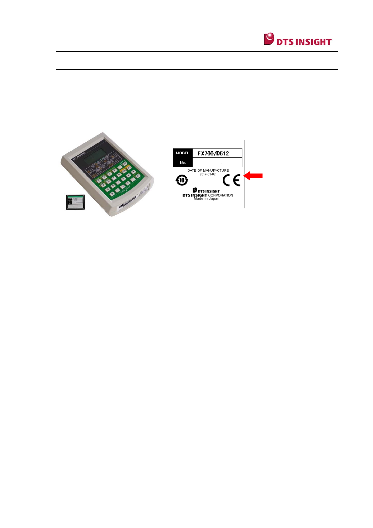
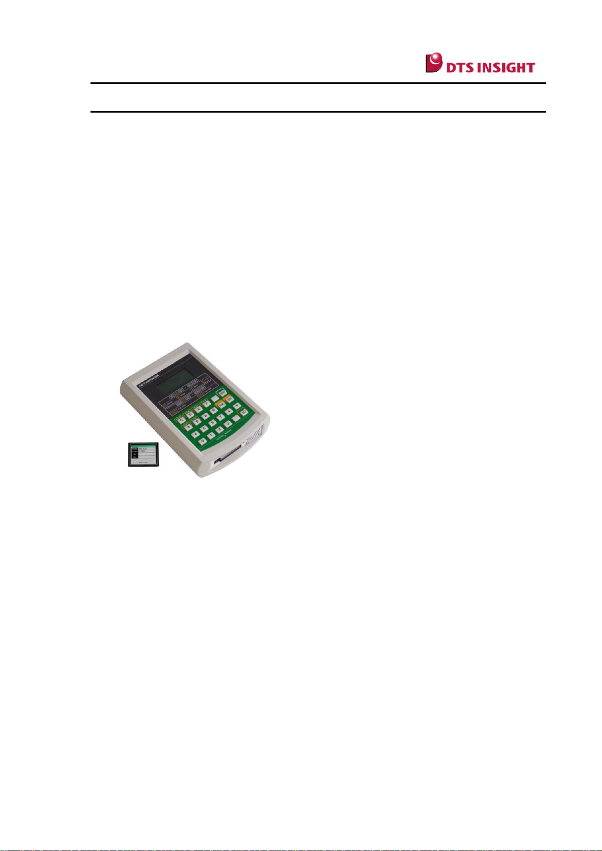
The following items are included in the hardware package of the NETIMPRESS.
(1) NETIMPRESS main unit (AF320/AF420/AF520/AF620/AF430)
(2) AC adapter specially built for the NETIMPRESS
(/AC4P INPUT: 100V to 240V OUTPUT: 12V)
(3) Control Module (Media: Compact Flash (CF) card)
(4) CD-ROM: 1 to 2 pieces (License Pack, Utility) depending on a target device
(5) Target probe, adapter, etc., which vary depending on a target device
3
3.2 Software
The following items are included in the software package of the NETIMPRESS.
(1) AZ490 (Remote Controller to download the various files, execute the device functions
and set up various parameters)
(2) AZ482 (F/DF Sheet Generator to create a file to set up an IP address to the programmer
main unit and download the files)
(3) AZ481 (Key File Generator to create an ID code Key to communicate with a PC, and a
SUM file)
4

4 Installing the Software
The software to make the various settings to the NETIMPRESS programmer is available at
our website:
https://www.dts-insight.co.jp/en/support/support_netimpress/top/index.php?m=Software
Download the following software from the above mentioned web site:
(1) AZ490 (Remote Controller)
(2) AZ482 (F/DF Sheet Generator)
(3) AZ481 (Key File Generator)
Since they are the self-expanding files, decompress them on a PC and install them.
Note:
When you complete installing them and if you choose the default setting, they will be
registered in [DTS INSIGHT Tools], which you can open by selecting [Start] → [Program].
5
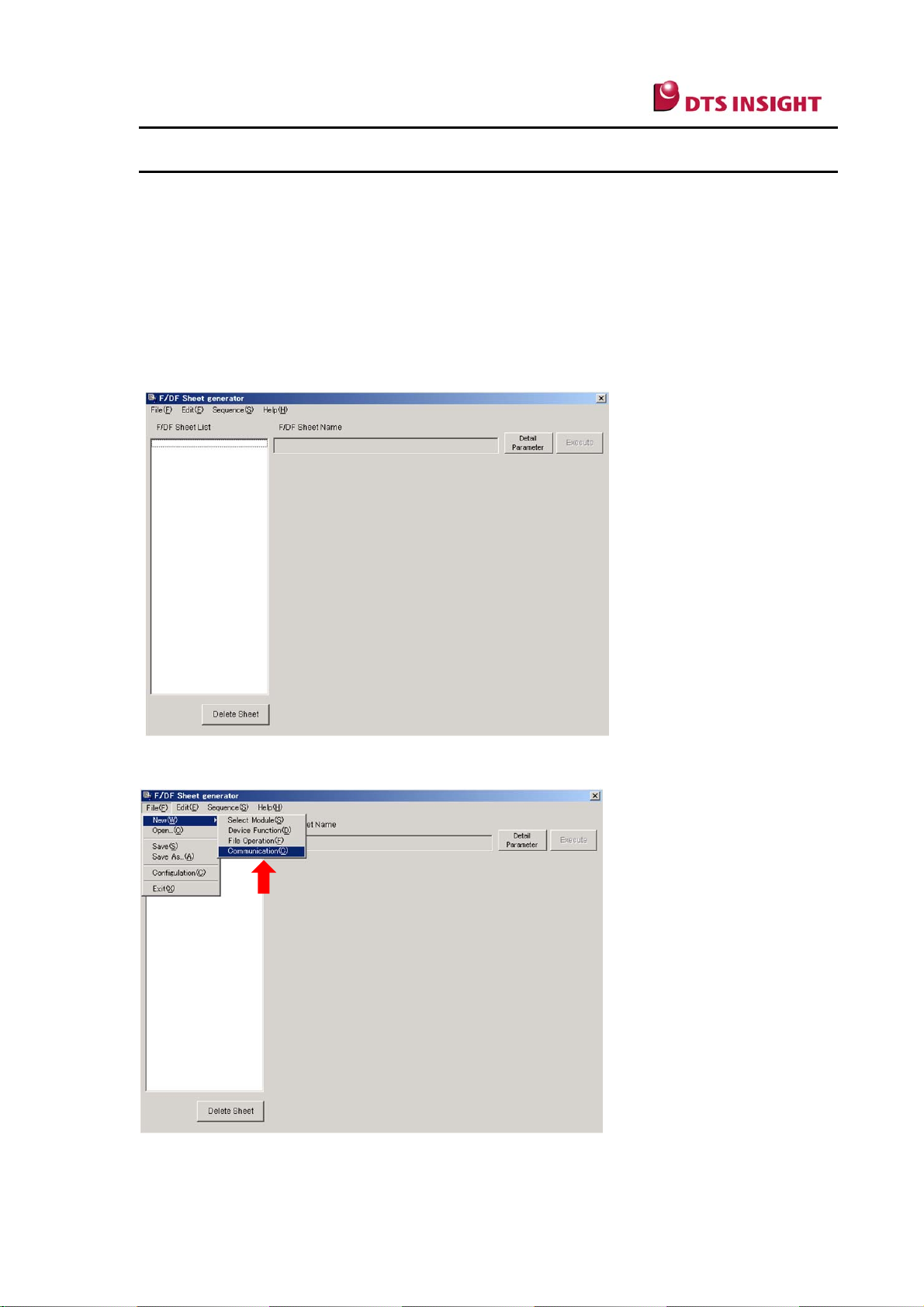
5 Setting up IP Address to Programmer Main Unit
To set up an IP address to the programmer main unit so as to control it via Ethernet from a
PC, follow the below steps.
* As a stand-alone, you can set IP address by using FUNC E2 to E4. For how to operate
NETIMPRESS as a stand-alone, refer to a chapter “Setting Ethernet” of an instruction
manual.
(1) Start up the AZ482 (F/DF Sheet Generator) that has been installed on your PC.
(2) From the Menu bar, select [File] → [New] → [Communication].
6
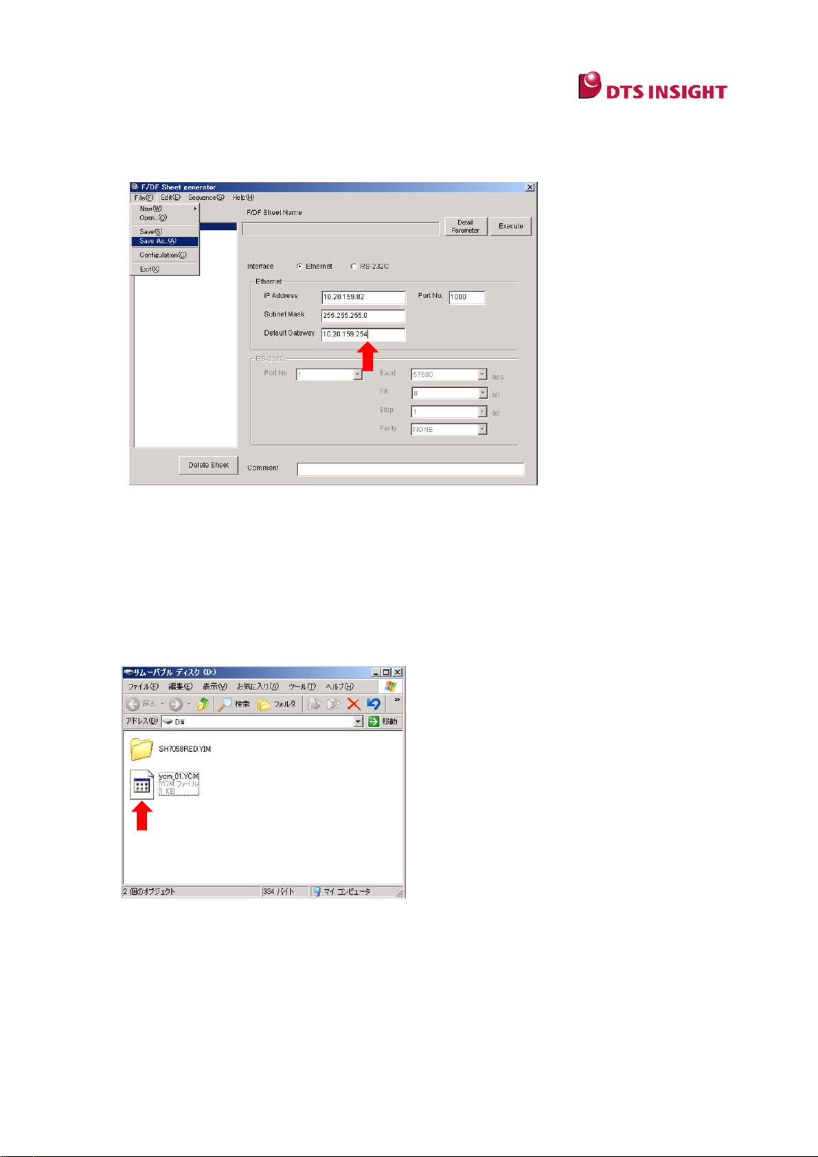
(3) Enter IP address, port information, etc. to set up in the programmer main unit, and select
[File] → [Save As] and enter a file name with extension “.ycm” to save. (This file name
can be changed.)
Note:
[Default Gateway] does not have to be set up in most cases, just enter “0.0.0.0”. When using
the NETIMPRESS via a router, enter an address of the router.
* Enter 1000 for Port No. if there is no problem on the network.
(4) Copy the xxx.ycm file you created to right underneath the drive of the Control Module (CF
card) by using the card reader of the CF card.
(5) Insert the Control Module into the slot of the NETIMPRESS main unit and turn on the
power.
(6) The message “YCM DATA SET?” is displayed on the LCD of the NETIMPRESS main
unit. Then, press either “EXE1” or “EXE2”. (For Mega/C”arNETIMPRESS , press EXE1
and EXE2, both of them are the user-defined keys with no names.)
7

The IP address information is set up in the NETIMPRESS and displayed on the LCD.
Then, the NETIMPRESS main unit is started.
8

6 Connecting with a PC (AZ490 Setting Remote Controller)
To set up environments to control the NETIMPRESS from the Remote Controller AZ490,
follow the steps below.
(1) Start the AZ490.
(2) Enter IP address and port number of the NETIMPRESS main unit and press
Communication Check .
When communication is established, the window as shown below (“File Transfer”) appears.
Then, communication between a PC and the NETIMPRESS main unit can be started.
9

10

7 Adding a Licence to the Control Module
To add a licence to the Control Module, follow the steps below.
(1) Click … button in the Add Licence field located in the center of the CF Card
Information tab.
(2) File selection window is shown. Select the licence file (xxx.YLC) that is provided in the
form of CD-ROM, and then click OK button.
(3) Click Add Licence in the Add Licence filed. Then the licence is added into CF card.
* The added licence information is written in the special area in CF card. The licence
information will remain even if you format the CF card.
11

8 Creating Impress Module Folder (YIM)
With the Control Module, you can save and maintain a programming object and
programming environments data in a folder called Impress Module folder (YIM). When you
finish adding a license, create the YIM folder and set up programming environments.
How to create YIM folder
(1) Click Create YIM folder in the IMPRESS Folder at the upper left of the File Transfer
tab. (As the Module Name dialog window appears, enter any name and click OK .
* In case that Create YIM folder button is dimmed, click [Control Module] which you can find
at the top of tree view on Folder/File List window.
12

(2) The name of YIM folder you have created is displayed in the Folder/File List window.
Then, right-click on the YIM folder you have created and select [Select] → [OK].
* You can select the folder by double-clicking the folder on the tree view of Folder/File List
window, or clicking Select YIM Folder on the main window.
(3) The YIM folder you have selected in Step 2 becomes the current folder and its name is
displayed at the top of the AZ490.
What is the Current folder?:
The files are loaded and the device functions are executed using the current folder. When
various setup files are loaded to the Control Module, they are copied to the current folder.
13

9 Downloading Files and Setting Programming Environments
This chapter explains the steps to download the various files to set up programming
environments to the current YIM folder.
It also explains how to download the definition program (extension: CM), parameter
(extension: PRM), and bundle files.
(1) Downloading the Definition Program
Click the Load Definition Program in the Control Module field to load the Definition
Program file (with extension CM) that is provided in the form of a CD-ROM.
(2) Downloading parameters
Select the Load Parameter in the Parameter Table filed to load the parameter file (with
extension “PRM”) that is provided in the form of a Micom pack download from our Website.
14

(3) Downloading the bundle files
Download the bundle files that are required for programming by pressing
the Copy File(Load) in the Bundle File field.
The KEY file, BTP file and AMK file are the major bundle files.
* Since the bundle files to be provided differ depending on each device, check with the
manual of the Control Module you use.
15

(4) Setting up parameters
The parameters you have downloaded in Step 2 are the default values and you need to
modify them according to your environments.
Open the Parameter Table 1 tab and make the settings. For details, see the Manuals for
Control Module and Micom-Pack. The parameters you need to modify are operating voltage,
clock, communication baud rate, etc.
* If you change the setting on this window, click OK button at the center of right side to
reflect the settings.
16

(5) Downloading a programming object
As you finish Step 1 to Step 4, most of programming environments are now set up. Then, the
next step is to download a programming object by clicking Load Object Data on the
Object Data field.
(6) Executing the device function
As you complete setting up programming environments and downloading a programming
object, all preparations for programming are done. You can now start programming by
executing the device functions (E.P.R normally) on the Basic Operation tab.
* E.P.R is a command to do a sequence of actions of delete, write, and read-check (verify)
the flash memory.
17

10 Using the Remote Controller AZ490
By using the Remote Controller AZ490, you can download the various files, set up
programming environments and execute the device functions.
The screen of the AZ490 consists of the following six tabs.
Host Interface Configuration tab to connect with the programmer
Basic Operation tab to execute the device functions
Parameter Table 1 tab to set up parameters
Parameter Table 2 tab to set up parameters, which is not user accessible.
CF Card Information tab to display CF card information, add licenses, and to format.
File Transfer tab to transfer the files
Among these six tabs, this chapter explains the three tabs mostly used:
1. Basic Operation--- Device function execution window
2. Parameter Table 1 --- Parameter setting window
3. File Transfer --- File transfer window
18

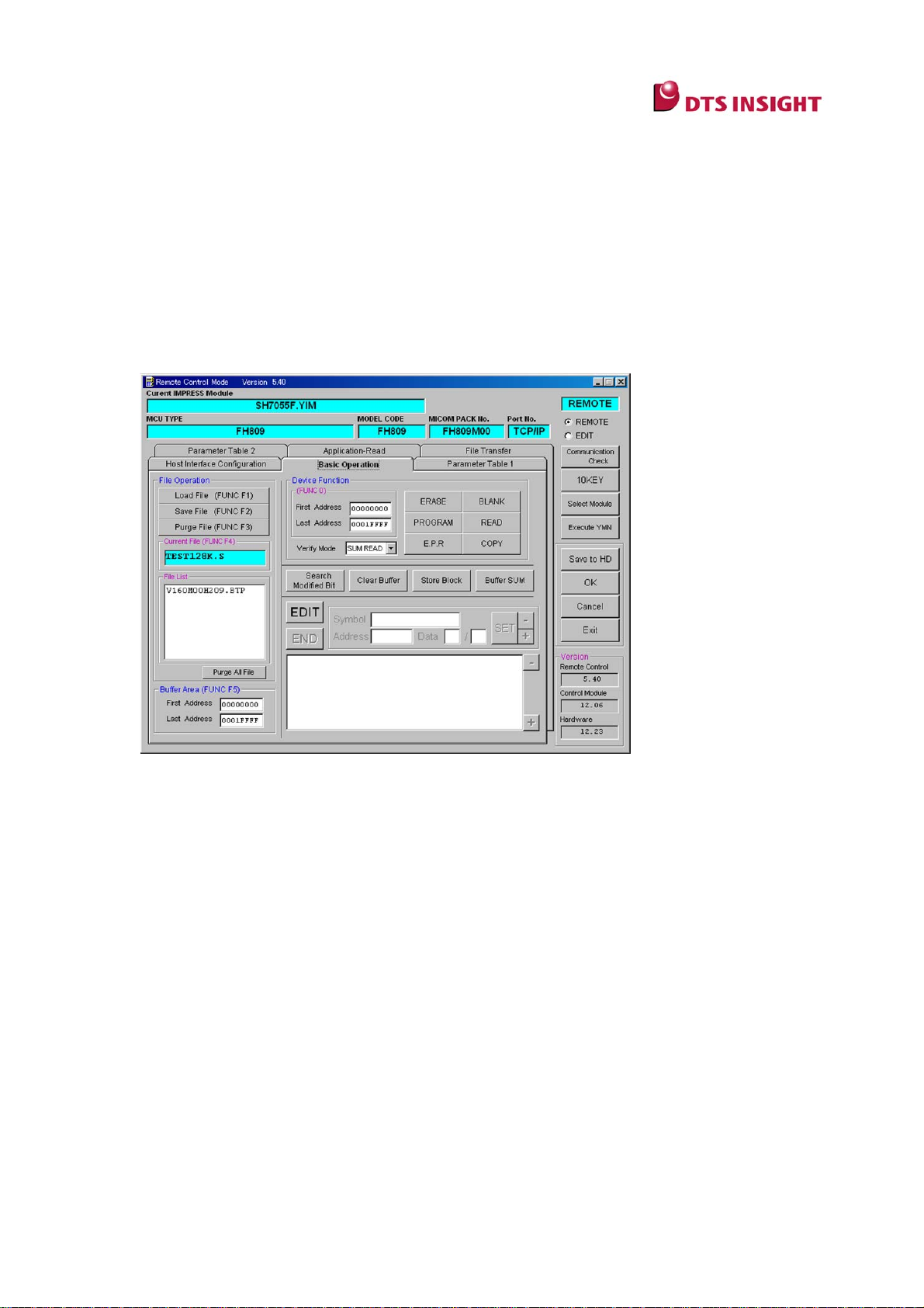
10.1 Basic Operation tab
The Basic Operation tab is mainly used to execute the device functions.
(3)
(4)
(1)
(2)
(1) Current IMPRESS Module
The name of YIM folder currently selected is displayed. (“SH7058RED.YIM” is displayed in
the above example.)
(2) Device Function
With this Device Function field, you can execute the various device functions.
(3) Current File
File name loaded by clicking Load Object Data in the Object Data of the File Transfer tab
is shown.
(4) File List
The files placed in the YIM folder (DOS area) currently selected are listed in the File List
field. The bundle files are listed. These are the files of objects that have been copied by
clicking Copy File(Load) in the Bundle File of the File Transfer tab.
19

10.2 Parameter Table 1 tab
The Parameter Table 1 tab is used to make the programming settings according to your
environments.
(5)
(5)
(6)
(6)
(7)
(7)
(5)
(8)
(8)
(5) MCU Type
The default device name is displayed, which can be changed.
The name set up here will be displayed in the LCD of the NETIMPRESS main unit. (“FH809”
is displayed in the above example.)
(6) TVcc Threshold
This is used to check whether the power of a target is turned on when the device functions
are executed. Enter a value of about 90% of a target power supply voltage.
(7) MCU Clock Frequency
Enter operation clock of a target.
(8) Data Communication
This field is used to set up communication between a device and the NETIMPRESS
programmer. Specify communication interface (UART or CSI) and set up baud rate.
20

10.3 File Transfer tab
(10)
(11)
(9)
The File Transfer tab is used to add a license, transfer a file required to set up programming
and a programming object, and work with a YIM folder (create/select/copy/delete).
(9) Folder/File List Window
This field is used to display YIM folder and other files to create, select, copy or delete them.
YIM folders you have created are listed. (“SH7055F.YIM” is displayed in the above
example.)
(10) IMPRESS Folder
This field is used to operate YIM folder and other files selected in Folder/File List Window.
For NETIMPRESS next, YIM folder of programmer can be saved on PC, or also you can
transfer YIM folder in PC by clicking a button on this field.
(11) File Transfer
Object Data: This field is used to transfer an object to program to buffer memory and save
contents of buffer memory to a PC.
Bundle File: This field is used to transfer the bundle files to the programmer and save them
in a PC.
Parameter Table: This field is used to transfer a parameter file (PRM) to the programmer
and save it in a PC.
Control Module: This field is used to transfer the definition program (CM) to the
programmer and save it in a PC.
21

11 Impress Module Folder (YIM)
11.1 Folder Management
With the Control Module, you can save and maintain a programming object and
programming environments data in a folder called Impress Module folder (YIM). The YIM
folder created in the Control Module can be saved in a PC using the card reader, for
example. You can build up exact same programming environments by sending the YIM
folder to other work site to provide work instructions.
Note:
To share information by sending the YIM folder, the license for the same definition program
has to be registered with the programmer.
Send these folder and file to other work site.
EXE1, EXE2
YIM folder:
For details about the YIM folder, see Instruction Manual, Section 5.5 “Impress Module Folder
Related”.
.csb file:
For details, see Instruction Manual, Section 6.1.2 “EXE Key Setting”.
By just sending the above two files to other work site, exact same programming
environments can be built up.
22

11.2 Folder Configuration
r
(1) You can create more than one YIM folder in the compact flash and switch them with the
function key. For details, see Chapter 8 “Creating Impress Module Folder (YIM)”, Step
(2).
(2) BTP(* .BTP) file and a user OJB such as .KEY, .YSM, etc. are saved in the DOS area.
(3) The buffer file (BUF.SYS) and the definition file (CM.SYS) of each one type are saved for
YIM folder you have created.
(4) Since CSB file is placed right under the control module as shown below, only one CSB
file can be used for one control module.
For a file you have downloaded by pressing the Object Data button, you can switch it
between keeping and clearing of Buffer RAM with [FUNC 9A]. For details, see the
Instruction Manual.
You can view the file configuration on the window of the Remote Controller just as you work
with Windows File Explorer.
(You cannot see the read-only area from REMOTE window.)
(1)
Control Module
Impress Module folder (A.YIM)
Impress Module folder (B.YIM)
DOS area
User OBJ
Read only
System folde
Buffer file
DOS area
(2)
(3)
Read only
.CSB
(4)
.YMN
23

12 Key File
The security function is built in the firmware of a flash microcomputer to prevent a third
person from reading and writing ROM illegally.
As the mechanism of the security function, a specific area of flash memory is set as an area
to store an ID code, and whenever access is tried from a serial programmer, the same data
with ID data written to the microcomputer is sent to the microcomputer as an ID code, and if
they are found not matching, the access is not allowed. Therefore, access can be made only
when you know what ID data is written to the microcomputer.
1. KEY file
The Key file is used to automatically issue an ID code to a microcomputer and unlock the
security when the programmer executes the device functions. Address where ID data is
stored, ID data size and value are saved in the Key file.
Download the Key file using the Copy File(Load) on the Bundle File field on the File
Transfer tab and place it in the YIM folder.
2. Security methods (Common)
You can execute the standard security function in the following two ways:
Specify security ID address and ID size.
Specify only a range of security ID and select any address within a specified address
range, and if data value of several bytes are matching, the security function is unlocked.
* Since specifications of the security function differ depending on a microcomputer of each
type, see the manual of the Micom Pack you use.
Creating a Key file
You can create a Key file using the Key File Generator AZ481.
To create a Key file, perform the following steps.
(1) Start up the AZ481.
24

(2) Enter address where ID is stored, ID size and ID data value.
In the above example, 0000608B is entered as security address, 8byte as ID size and
IEC213971A15B443 as data value respectively.
(3) Save KEY file
Select [File] → [File Save]. Then, save the KEY file.
* Note that a Key file name has to be the same name with an object.
Example: Object file name: For TEST128K.MOT, set TEST128K.KEY for KEY file.
25

13 SUM Check Function of YSM file
This function is used to check a SUM value of data whenever executing the device functions
so as to prevent programming illegal object data. This function is very useful in case data of
an object to program is garbled all of a sudden.
By saving a SUM value of an object in YSM file, data is automatically checked by the
NETIMPRESS.
When execution of the device functions is completed, a SUM value in YSM file is compared
with a SUM value at a time of execution of the device functions. In case they are not
matching, it results in an error with the message “YSM CHECK ERROR”.
Download YSM file using the Copy File (Load) of Bundle File on the File Transfer tab
and place it in the YIM folder.
Creating a YSM file
To create YSM file, perform the following steps.
(1) Start up the Key File Generator AZ481.
(2) Create YSM file
Select [Address Sort Off] from Option on the menu bar, and enter the data. (Basically,
enter only No. 1 and No. 2 lines.)
No.1: Enter SUM value
No.2: Flag to Check SUM/Do not check SUM
No. 1: data
Address = 00000000 (Fixed)
Size=1 (Size of SUM. For 1byte, enter “1”, for 2byte, enter “2”.)
Data = SUM (Calculate SUM value by using “BufferSUM” of Basic Operation of AZ490)
26

No.2: flag
Address = 00000000 (Fixed)
Size = 1 (Fixed)
Enter Data = “ 01 “ or “ 00 ” (Check SUM = 01, Do not check SUM=00)
NO.1
NO.2
* For SUM check of YSM file, there is also a function to check the data in the certain area of
buffer memory. It is useful to check the version of file. For details, see a manual of NET
IIMPRESS main unit.
(3) Save YSM file
Select [File] → [File Save]. Then, save the YSM file.
Select YSM File(*.YSM) for the file type.
* Note that YSM file name has to be the same name with an object.
27

14 CSB File
A CSB file is used to execute command sequence. Execution sequence of a CSB file is
assigned to the two EXE keys on the upper part of the NETIMPRESS main unit.
Set up a command with CSB file.
EXE1
EXE2
LK1,01,DF;EPR
(Pressing EXE1 executes ERP.)
LK2,01,DD;Program
(Pressing EXE2 executes PR.)
About the specifications of a CSB file
A CSB file can be edited with a text editor. After editing, specify any name and save it with
extension "csb”.
Only one CSB file can be placed in the root directory of the Control Module. Up to 16
commands can be assigned.
About the format of a CSB file
The table below lists the format to set up a CSB file.
(1) (2) (3) (4) (5) (6)
LK1 , CNT , C1 , C2 , … , C16 ; Comment
LK2 , CNT , C1 , C2 , … , C16 ; Comment
(1) KEY No: LK1 = EXE1, LK2 = EXE2
(2) ” , “(1byte): Command delimiter
(3) CNT: the number of commands executed (in decimal)
(4) Command
(5) ” ; “ (1byte): Comment delimiter
(6) Comment: Describe comment (Any byte size + CRLF)
* Break is necessary at the end of line of LK2.
* If you cannot allocate the function to neither EXE1 nor EXE2, set 00 the number of
execution command (CNT). You cannot omit the whole line starting with LK1 or LK2.
28

About CSB file
(1) Sample 1 (the standard sample: Test.csb)
The standard CSB file named “Test.csb” is provided, which contains the following.
Sequence to be executed:
EXE1= Execute ERP
EXE2= Execute PR
* To execute the above command sequence, a YIM folder has to be selected in advance.
LK1,01,DF;EPR
LK2,01,DD;Program
(2) Sample 2
Sequence to be executed:
EXE1 = Load a specified YIM folder
EXE2 = Execute ERP
LK1,01,FB0 (SH7058RED.yim);CHANGE YIM
LK2,01,DF;E.P.R
When “EXE1“ is pressed, SH7058RED.YIM is loaded as a current IMPRESS Module.
When “EXE2“ is pressed, EPR is executed on contents of SH7058RED.YIM to a target.
(3) Sample 3:
Sequence to be executed:
EXE1 = Program the two YIMs continuously
EXE2 = Execute Erase
This command sequence can be used in the following two cases:
To program external flash memory dividing in two parts of the first half and second
half
To program both of internal flash memory and external flash memory on a board
connected with external flash memory connected to a microcomputer
LK1,04,FB0(SH7750R01.yim),DF,FB0(SH7750R02.yim),DF;2file sequence EPR
LK2.01.DC;Erase
29

When “EXE1“ is pressed:
SH7750R01.YIM (the first half of external flash memory) is loaded as the current
IMPRESS Module.
EPR is executed on contents of SH7750R01.YIM to a target.
SH7750R02.YIM (the second half of external flash memory) is loaded as the current
IMPRESSS Module.
EPR is executed on contents of SH7750R02.YIM to a target.
When “EXE2“ is pressed:
Flash memory of a target is erased.
30
 Loading...