

Page 1
快速操作手冊 - Quick Guide User Manual
Page 2
fpv
RAcing
Table of Contents
Important*
Introduction
1
1
2
3 - 9
10
11
12
13
141516 -19
19
20
21
22
26
Important Notes / Warning Label Legend
Safety Note (Install Compatible RC Receiver / Setup the Video Link)*
Safety Note (Receiver Setting - CleanFlight / Pre-flight Check)*
Safety Note (Racing Instruction / Remove Props / Li-po Low V. Alarm)
Safety Note (General) / Packing Contents
Details Packing Contents
Equipment Required / Flight Steps / Motor Unlock
Main Control Board Introduction / Flight Control Introduction
Welding Introduction
Assembly Introduction
Main Blade Assembly Introduction
Control Mode
(AUX1) Flight Mode Switch / (AUX2) OSD and Beeper Switch
Compatible Open Source
Spare Parts
Specifcations
23 - 25
1
Safety Note (General / Battery Installation)
Page 3
fpv
RAcing
Introduction
1
Congratulations on purchasing the DTSQ220 Race QUAD. To ensure your continued enjoyment,
please take the time to thoroughly read through this operating manual before using.
Important Notes
Radio Control (R/C) multicopters are not toys. R/C multicopters utilize various high-tech components to
achieve superior performance. Improper use of this product can result in serious injury or even death.
Please read this manual carefully before operating, and make sure to be conscious of your own
personal safety and the safety of others nearby when operation all DTS products. Manufacturer and
seller assume no liability for the operation or the use of this product. This product is intended for use
only by adults with experience flying remote control aircraft at legal flying fields. After the sale of this
product we cannot be held liable over its operation or usage.
As the user of this product, you are solely responsible for operating in a manner that does not in danger
yourself and others or result in damage to the property of others.
Safety Notes (General)
Fly only in safe areas, away from other people. Do not operate R/C aircraft indoors or within the
vicinity of homes or crowds of people. R/C aircraft are prone to accidents, failures, and crashes due
to a variety of reasons including: lack of maintenance, pilot error, and radio interference. Pilots are
responsible for their actions and damage or injury occurring during the operation or as of a result of
R/C aircraft models.
Prior to every flight, carefully check all parts such as blades, screws, frame, arms, etc; ensure they
are firmly secured and show no unusual wears, or unforeseen danger may happen.
Warning Label Legend
Do not attempt under any circumstances.
Mishandling due to failure to follow these instructions may result in serious
damage or injury.
禁 止
FORBIDDEN
警 告
WARNING
Safety Notes (Battery Installation)
DTS Q-series has a flexible battery mounting system, and uses an industry-standard XT-60(AMASS)
connector. This allows it to use a wide range of different batteries.
Voltage:3s (11.1V) pack is recommended. Running 4s (14.8V) is an extremely fast race-quad, which
can easily get a pilot into trouble.
Capacity:1000mAh~1500mAh Li-Po battery is recommended.
C Rating:30C or above Li-Po battery is recommended.
When installing the selected battery, pay attention to the Center of Gravity mark on the bottom.
Page 4
Safety Note (Intall Compatible RC Receiver)
Safety Note (Setup the Video Link)
2
DTS Q-series is compatible with CPPM (all PPM channels down one single cable) receivers out of the
box, and can support S-Bus, or Spektrum receivers with an optional cable.
It is also compatible with standard R/C receivers with multiple channels of PWM out
(standard servo hookups)
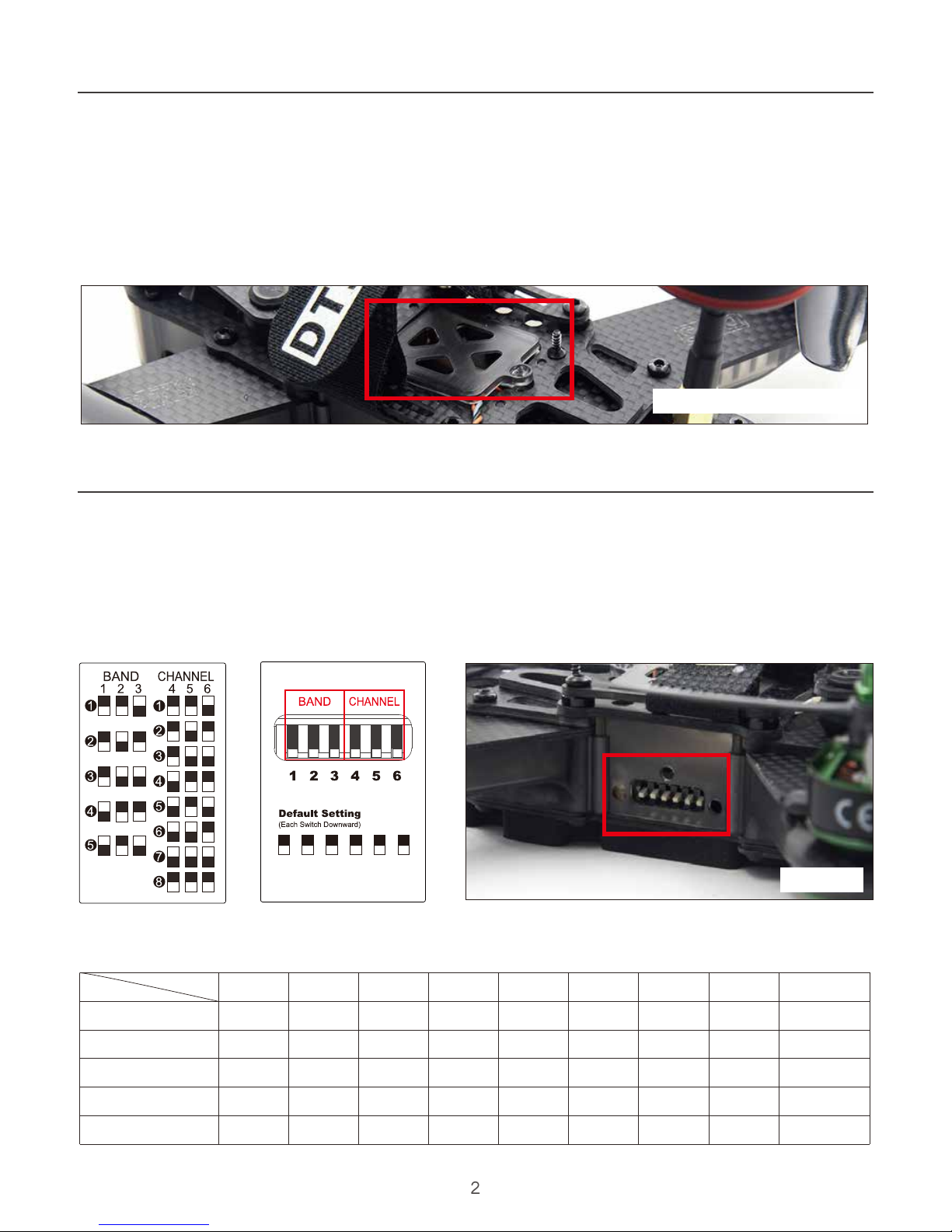
DTS Q-series are using the following method to switch the channel(Default Channel switcher : All
downward):
(Pilot should follow the ISM channel chart as below to connect quad and goggles)
DSM Binding : Plug DSM receiver into correspondence port, and switch all channel switch to top,
power on the main control board. Then it will enter the binding mode with alert“Bi~~~”.
ISM channel chart:
5733
5658
5740
5705
5865
5752
5695
5760
5685
5845
5771
5732
5780
5665
5825
5790
5769
5800
5645
5805
5809
5806
5820
5885
5785
5828
5843
5840
5905
5765
5847
5880
5860
5925
5745
5866
5917
5880
5945
5725
Band B
Race
IRC/FS
Band E
Band A
Band
Channel
1 2 5 6 7 843
1
2
3
4
5
Channel Switch
Diagram:
Default Channel switcher:
All downward
Side View
fpv
RAcing
Receiver Placement Diagram
Page 5
USB Socket Placement
Safety Note (Receiver Setting - CleanFlight)
3
fpv
RAcing
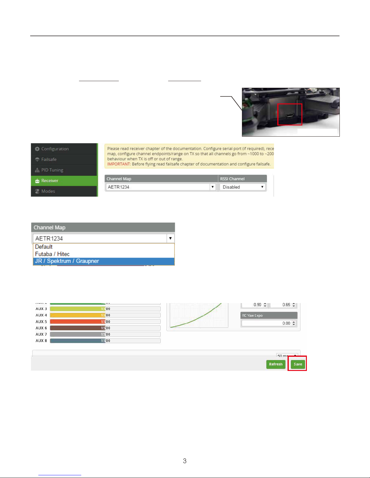
Select Receiver Signal (PWM,PPM,SBUS,DSM)
- Download CleanFlight into your Computer as
https://chrome.google.com/webstore/detail/cleanflight-configurator/enacoimjcgeinfnnnpajinjgmkahmfgb?hl=en-US
- Download the Version 1.2.4 and install it as Extensions in Goggle Chrome as
https://github.com/cleanflight/cleanflight-configurator/releases/tag/CLFL_v1.2.4
- Connect the Main Control Board to computer by USB Cable
- Enter the Receiver table
- Select the Receiver Brand which you are using -
Clean Flight Setting:
Press “Save” after setting.
Select the receiver brand which you are using - AETR1234(Futaba/Hitec) or
TAER1234(JR/Spektrum/Graupner)
Enter the Receiver table
Page 6

Safety Note (Receiver Setting - CleanFlight)
4
fpv
RAcing
PWM Signal
- Download CleanFlight into your Computer as
https://chrome.google.com/webstore/detail/cleanflight-configurator/enacoimjcgeinfnnnpajinjgmkahmfgb?hl=en-US
- Download the Version 1.2.4 and install it as Extensions in Goggle Chrome as
https://github.com/cleanflight/cleanflight-configurator/releases/tag/CLFL_v1.2.4
- Plug PWM receiver into correspondence port
(Port Position please refer to P.14- Main Control Board Introduction)
- Power on the Main Control Board
- Connect the Main Control Board to computer by USB Cable
Clean Flight Setting : Enter Ports Table
Press”Save and Reboot”after each step
Testing : Ensure 6 channel is operating normally at receiver table (After test, power off the quad,
then disconnect)
Enter Configuration or Receiver Table
USB Socket Placement
Page 7

Safety Note (Receiver Setting - CleanFlight)
5
fpv
RAcing
PPM Signal
- Download CleanFlight into your Computer as
https://chrome.google.com/webstore/detail/cleanflight-configurator/enacoimjcgeinfnnnpajinjgmkahmfgb?hl=en-US
- Download the Version 1.2.4 and install it as Extensions in Goggle Chrome as
https://github.com/cleanflight/cleanflight-configurator/releases/tag/CLFL_v1.2.4
- Plug PPM receiver into correspondence port
(Port Position please refer to P.14- Main Control Board Introduction)
- Power on main control board
- Connect the Main Control Board to computer by USB Cable
USB Socket Placement
Clean Flight Setting : Enter Ports Table
Press”Save and Reboot”after each step
Testing : Ensure 6 channel is operating normally at receiver table (After test, power off the quad,
then disconnect)
Enter Configuration or Receiver Table
Page 8
Safety Note (Receiver Setting - CleanFlight)
6
fpv
RAcing
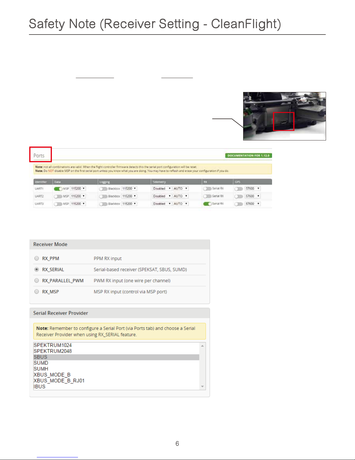
SBUS Signal
- Download CleanFlight into your Computer as
https://chrome.google.com/webstore/detail/cleanflight-configurator/enacoimjcgeinfnnnpajinjgmkahmfgb?hl=en-US
- Download the Version 1.2.4 and install it as Extensions in Goggle Chrome as
https://github.com/cleanflight/cleanflight-configurator/releases/tag/CLFL_v1.2.4
- Plug PWM receiver into correspondence port
(Port Position please refer to P.14- Main Control Board Introduction)
- Power on main control board
- Connect the Main Control Board to computer by USB Cable
USB Socket Placement
Clean Flight Setting : Enter Ports Table
Press”Save and Reboot”after each step
Testing : Ensure 6 channel is operating normally at receiver table (After test, power off the quad,
then disconnect)
Enter Configuration or Receiver Table
Page 9
Safety Note (Receiver Setting - CleanFlight)
7
fpv
RAcing
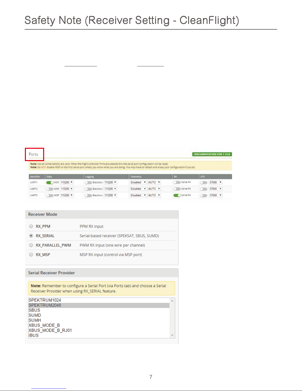
DSM SIgnal
- Download CleanFlight into your Computer as
https://chrome.google.com/webstore/detail/cleanflight-configurator/enacoimjcgeinfnnnpajinjgmkahmfgb?hl=en-US
- Download the Version 1.2.4 and install it as Extensions in Goggle Chrome as
https://github.com/cleanflight/cleanflight-configurator/releases/tag/CLFL_v1.2.4
- Plug DSM receiver into correspondence port
(Port Position please refer to P.14- Main Control Board Introduction)
- Switch all channel switch to bottom
- Power on the main control board. Then it will enter the binding mode with alert“Bi~~~”
- Binding Transmitter and Receiver
- Power off the main control board, then switch all channel switch to top
- Power on the main control board, connect the mainboard to computer by USB
Press”Save and Reboot”after each step
Testing : Ensure 6 channel is operating normally at receiver table(After test, power off the quad,
then disconnect)
Clean Flight setting: (Enter Ports Table)
Enter Configuration
or Receiver Table
Page 10

Safety Note (Receiver Setting - CleanFlight)
8
fpv
RAcing
Receiver Channel Range Setting
- Adjust the transmitter parameter (Travel), let Roll, Pitch, Yaw, Throttle
Lowest value within 1000 - 1096, and the largest value within 1944 - 1999 in the Receiver Table.
- AUX 1 and 2 are on your transmitter, and there will be have 3 switches.
Default mid-point
DSM/PPM - 1500
SBUS/PWM - 1520 .
Page 11

Safety Note
(Pre-flight Check)
9
fpv
RAcing
Motor Lock Mode
- Throttle channel locked (Middle condition LED flashing in Yellow)
Motor Unlock Mode
- Throttle channel unlocked(Middle Condition LED solid in Blue and Green)
Chcek the transmitter stick and condition LED is it at the same direction
(MUST process in Motor Lock Mode)
- Push Elevator Stick to Top (Left / Right Condition LED flashing in Yellow)
- Push Aileron Stick to Left (Left Condition LED flashing in Yellow)
- Push Aileron Stick to Right (Right Condition LED flashing in Yellow)
- Push Throttle Stick to Top in Motor Lock Mode (Middle Condition LED solid in Blue and Green)
Page 12

fpv
RAcing
Safety Note (Racing Instruction)
The current generation of FPV Analog video link brings many advantages. Low-cost, and zero latency
being two of the most significany. They do however suffer from less than ideal selectivity, even when
using large channel spacing as is the case with RaceBand. If a few simple rules are followed, quad
racig can be a lot of fun.
This is an absolutely golden rule. Landing your quad near another pilot, especially one who is at a
significant distance.
1) NEVER land near another pilot
2) NEVER walk back to the pilot area with a powered-up quad
3) POSITION the launch and landing zone as far from the pilot area as
possible
4) ALWAYS warn in-air pilots before powering up a quad, even if you KNOW
it is on a different channel
This is the most common cause of issues at the race track. When retrieving a model, unplug the
battery before walking back to pilot area.
This ensures that collisions at race start don’t affect other pilots. A distance of at least 10 meters is
recommended, more than this is a bonus.
Warn pilots, and be ready to power down IMMEDIATELY if a pilot is affected, and wait until he lands.
Remember that it only takes a seond or two, when flying race quads at speed, to crash and damage
the quad, and whatever (whoever) it hits.
Safety Note (Remove Props)
Safety Note (Li-po Low Voltage Alarm)
Mini-quad props can do come serious damage when coming in contact with human skin, risk do
deep cuts and lacerations should be avoided at all cost.
So when you are working on a quad with the battery connected, it is highly recommended to
REMOVE ALL PROPS, unless you are just about ready to fly.
DTS Q-series quad included LI-po Low Voltage alarm. Alert“Bi~Bi~” when battery in low voltage to
prevent over discharge. This function is compatible with GWY COBRA V, due to it has buzzer function.
禁 止
FORBIDDEN
禁 止
FORBIDDEN
警 告
WARNING
警 告
WARNING
10
Page 13

Any time found motor is operating abnormal. Turn off the throttle and check the reason
immediately. If not, damage will cause motor to be broken.
警 告
WARNING
fpv
RAcing
Safety Note (General)
Do not fly near buildings , high voltage cables, or tress to ensure the safety of yourself.
禁 止
FORBIDDEN
Do not attempt to modify the aircraft to alter its intended design. Please use only designated
replacement parts listed in the manual to ensure its design structural integrity.
禁 止
FORBIDDEN
Do not fly your model in inclement weather, such as rain, wind, snow or darkness.
禁 止
FORBIDDEN
R/C aircraft are made of various forms of plastics, such as carbon fiber and polyethylene.
Plastics are very susceptible to damage or deformation from extreme heat and cold climate.
警 告
WARNING
Frequency interference can cause your model, or other models to crash. Then guidance
provided by an experienced pilot will be invaluable for the assembly, tuning, trimming, and
actual first flight or unforeseen danger may happen.
警 告
WARNING
Operate this unit within your ability. Do not flywhile feeling impaired, as improper operation may
result in danger.
警 告
WARNING
During the operation of the multicoptere, the rotor will be spiinning at a high rate of speed. The
blades are capable of inflicting serious bodily injury and damage to surrounding properties.
警 告
WARNING
Packing Contents
Q180 Quadcopter
Q180 - Main Props
(CW x 2 , CCW x 2)
5.8G Circular Polarization Antenna
Parts / Tools Pack
11
Page 14

fpv
RAcing
Details Packing Contents
Q220 Quadcopter
M2.5x6mm x 6 / M2x5mm x 6
Round Head Socket Screw
M2.5x6mm x 1 / M2.5x6mm x 1
L Shape Hex Key
Landing Skid - Rubber
Velcro (Hard x 1 Rough x 1)
Q220 - Main Props
Hex Handle (For Main Props)
Receiver Signal Cable
(SBUS,DSM2/X)
5.8G Circular
Polarization Antenna
Receiver Signal Cable
(PWM,PPM)
12
Page 15

fpv
RAcing
Equipment Required
(Aircraft / Multicopter system)
Transmitter - 6 Channel or above
Receiver - 6 Channel or above, PPM,DSM,SBUS signal
FPV Goggle Balance Charger 3 cells or 4 cells Li-po Battery
Flight Steps
1. Install Receiver (self-provided) (Please refer to P.2 - Intall Compatible RC Receiver) to quad
2. Install Battery (self-provided) (Please refer to P.1 - Battery Installation)
3. After binding (self-provided) Receiver and Transmitter (self-provided), please go to the
pre-flight check (Please refer to P.9 - Pre-flight check)
4. Install Props (Please refer to P.19 - Main Blade Assembly Introduction)
5. Motor Unlock (Please refer to P.13 - Motor Unlock)
Motor Unlock
After Binding, Place the throttle stick at the bottom and push the aileron stick to the rightmost for at least
3 second . Then release.
Mode 1 Mode 2
Aileron Stick Throttle Stick Throttle/Aileron Stick
13
Page 16

fpv
RAcing
Main Control Board Introduction
1. 5V Camera Socket (with VOL-L/R) 5 PIN
2. 5V Camera Socket 3 PIN
3. 12V Camera Socket 4PIN
4. Green LED Light Socket (Front)
5. B. ESC Control Signal Socket S4
6. 5.8G Video Socket
7. Green LED Light Socket (Front)
8. B. ESC Control Signal Socket S2
9. B. ECS Power Connecter S2
10. OSD Parameter Adjustment Socket
11. B. ECS Power Connecter S4
12. Low V. Alarm Singal Input / Video R channel Socket
13. B. ESC Control Signal Socket S6
14. B. ESC Control Signal Socket S5
15. DSM Signal Input Socket
16. USB Signal Input Socket
17. SBUS Signal Input Socket
18. PWN Signal Input Socket
19. Flight Control Socket
20. Channel Switcher
21. External Buzzer / Conditional LED Socket
22. PPM Signal Input Socket
23. B. ESC Control Signal Socket S1
24. Red LED Light Socket (Rear)
25. B. ECS Power Connecter S1
26. Flight Control Buzzer
27. Li-Po Battery Socket
28. B. ECS Power Connecter S3
29. B. ESC Control Signal Socket S3
30. Red LED Light Socket (Rear)
FrontRear
1
6
4
5
2
3
7
9
10
13
14
12
30
29
28
25
27
26
23
22
21
24
11
8
19
20
16
18
17
1 1
2
3
5
4
15
Flight Control Introduction
1. Flight Control Socket
4. Sonar sensors and
Signal strength input socket
2. GPS or DATA Socket
5. BOOT Switch
3. Geomagnetic sensor and
Barometer socket
AUX2 AUX1 CH4 CH3 CH2 CH1 5V GND
14
PWM Wiring Diagram
Page 17

fpv
RAcing
Welding Introduction
ESC
ESC
ESC
S1
S3
S4
S2
FRONT
ESC
Motor
Motor
Motor
Motor
15
Page 18

fpv
RAcing
007
008
006
005
006
010
009
004
010
004
003
001
011
003
002
013
012
023
015
015
016
014
007
Step One Diagram
1
Front Body Cover (Plastic)
Rear Body Cover (Plastic)002
No.
003
Mount Rod for Front and Rear
004 Arm Cover (Front)
Specification Quantity
001
005 Left Body Cover (Plastic)
008 Right Body Cover (Plastic)
007 LED Light Set (Green)
006 Arm Cover (Rear)
009 Mount Rod for Center
010 LED Light Set (Red)
012 Main Control Board
011
LED Light Set (F/C Condition)
013 Main Plate (Bottom)
014 M2*6 Screw
015 M2.5*6 Screw
016 Top Fixed Plate (Front)
023 M2*5 Screw
4
2
1
2
2
1
2
8
2
1
1
1
8
1
2
1
Assembly Introduction
(Before Assembly, Ensure Motor and ESC has been welding on the Main Control Board)
16
Page 19

fpv
RAcing
017
018
019
020
021
023
030
022
023
023
029
024
028
027
026
025
4
Camera Damping Rod
Camera Damping Plate018
NO.
019
Camera Damping Ball
020 Antenna mount
Specification Quantity
017
021 Top Fixed Plate (Front)
024 M2*12 Screw
023 M2*5 Screw
022 Camera Damping Ball Ring
025 Camera Mount
026 M2*16 Screw
028 Camera Mount
027 FPV Camera
029 M2 Screw Nut
030 Video Tx Holder
4
1
2
4
4
1
1
1
1
1
1
1
1
Assembly Introduction
(Before Assembly, Ensure Motor and ESC has been welding on the Main Control Board)
Spare Parts DTS006871
(Optional Equipment)
Step Two Diagram
17
Page 20

fpv
RAcing
CW Brushless Motor
CCW Brushless
Motor
CCW Brushless Motor
CW Brushless Motor
035
035
031
036
043
032
061
036
033
037
034
023
044
060
039
023
034
046
047
038
041
038
039
040
042
045
042
045
Assembly Introduction
(Before Assembly, Ensure Motor and ESC has been welding on the Main Control Board)
Step Three Diagram
047 Flight Control Holder (Bottom)
1
M2*5 Screw023
No.
031
Battery Fixed Plate (Side)
032 O Ring
Specification Quantity
033
Cover for Receiver Placement
036 M2.5*8 Screw
035 M2.5*12 Screw
034 Antenna Mount
037 Battery Fixed Plate (Center)
038 CW Brushless Motor
040 Front Arm Cover (Plastic)
039 CCW Brushless Motor
041 Rear Arm Cover (Plastic)
042 Motor Mount
043 M2*7 Screw
044 5.8GHz Antenna Mount
046
Flight Control Holder (Top)
2
2
1
1
4
4
2
2
4
1
2
1
2
1
045 M3*6 Screw
16
1
060 Rear Fixed Plate (TOP) 1
061 M2*5 Screw
1
4
18
Page 21

fpv
RAcing
1
Channel Switcher Cover
Landing Skid (Sponge)056
No.
057
5.8G Antenna
058 Bullet Head Nut (CW)
Specification Quantity
055
059 Bullet Head Nut (CCW)
1
2
2
1
1
M2*5 Screw
Antenna Mount A048
No.
049
Antenna Mount B
050 Extension Tube
Specification Quantity
023
051 CCW Blade
054 USB socket Cover
053 Landing Skid (Sponge)
052 CW Blade
1
2
2
2
1
1
1
059
058
059
044
048
050
049
023
051
057
052
053
054
056
055
Main Blade Rotation Direction
Bullet Head Nut Tightening Direction
Main Blade Rotation Direction
Bullet Head Nut Tightening Direction
Bullet Head Nut
Tightening Direction
Main Blade
Rotation Direction
Main Blade Rotation Direction
Bullet Head Nut Tightening Direction
Main Blade Rotation Direction
Bullet Head Nut Tightening Direction
Assembly Introduction
Main Blade Assembly Introduction
(Before Assembly, Ensure Motor and ESC has been welding on the Main Control Board)
19
Page 22

fpv
RAcing
Flight Control Introduction
Mode 1
Mode 2
Throttle
Rudder Aileron
Elevator
Elevator
Rudder Aileron
Throttle
Mode 2 is the most common mode in USA, always use on RC Helicopter and Multicopter.
To identify Mode 2, we can find where is the throttle stick, if the left stick push to the top and it
wasn’t bounce back to middle, it should be Mode 2.
Mode 1 we can find it in Euro usually.
To identify Mode 1, we can find where is the throttle stick, if the right stick push to the top and it
wasn’t bounce back to middle, it should be Mode 1.
Otherwise, Mode 3 and Mode 4 is a very special control mode, we won’t use these mode if you are
beginner, either you very understand these mode already, so we won’t explain it over here.
20
Page 23

This mode is the preferred mode for the more advanced mini-quad pilot. In many ways it is the
simplest mode, but also the hardest mode to learn.
In Acro mode, the accelerometer part of the IMU is not used, only the Gyro.
Because of this, the quad will not self-level, explaining the steep learning curve for this mode.
To learn this mode, it is recommended to start flying the quad FPV, in Level mode, get some altitude,
and switch into Acro mode.
Landings in Acro mode can be a bit challenging for the beginner, so switching to Level mode before
landing is a reasonable way to deal with this.
Acro mode is the ideal mode to have fun with flips and rolls.
fpv
RAcing
(AUX1) Flight Mode Switch
Three flight modes are configured by the Clear Flight, and are maped by default to channel 5 (AUX1)
of the R/C Tx.
These modes are as follows:
Horiz (Pos 2)
Horiz mode is a bit of a hybrid mode. It does auto-level, buy also allows flips and rolls.
Angle (Pos 1)
Angle mode is the easiest to learn. When the sticks are centered, the flight controller is always working
to level the quad.
Acro (Pos 3)
21
(AUX2) OnScreenDisplay and Beeper Switch
OSD and Beeper Switch are configured by the Clear Flight, and are maped by default to channel 6
(AUX2) of the R/C Tx. These functions are as follows:
Display OSD on your Goggles or Monitor (Pos 1)
Do not show OSD on your Goggles or Monitor (Pos 2)
Switch on Beeper on your Quad (Pos 3)
Page 24

The development of the DTS, flight control firmware has referenced from the popular open source(F3),
it would not have been possible without the effort of a large team of individuals who invested in the
open source flight controller software that running on the DTS.
The variant of the open source flight controller firmware that we chose to power the DTS is Clenflight,
mainly die to it is solid support of the OneShot ESC control protocol.
Since the OSD firmware needs an intimate knowledge of the flight controller API, care must be taken
when installing updated Cleanflight builds.
DTS team may not have support for Beta, and recently released Cleanflight builds the day they are
released, buy we are committed to keep up with changes.
Check the DTS product page for compatibility information.
Clean Flight Configurator Connection
To hook up the Clieanflight Configurator, hook up a Personal Computer via a standard Micro-USB
cable, to the connector on DTS Q-series.
Be aware that making certain changes via the configurator may make operate abnormal. Please
backup for resetting factory settings Before making any changes.
fpv
RAcing
Compatible Open Source
22
Page 25

fpv
RAcing
Spare Parts
Body Cover (Four Sides)
DTS006881
Arm Cover (Plastic)
DTS006882
LED Light Set (Front / Rear)
GWY006883
Motor Mount Set
DTS006885
Brushless Motor (CCW)
DTS006887
Brushless Motor (CW)
DTS006888
Main Plate (Bottom)
DTS006889
Main Fixed Plate (Front/Rear)
DTS006890
Top Fixed Plate (Front)
DTS006891
Damping Ball Set (4PCS)
DTS006892
Top Fixed Plate (Center/ Rear)
DTS006893
Mount Rod (Long) for Front / Rear
DTS006855
Mount Rod (Short) for Center
DTS006856
LED Light Set (F/C Condition)
GWY006858
Camera Mount Set
DTS006859
Antenna Mount Set
DTS006861
Bullet Head Nut CW/CCW
DTS006866
for Action Camera
DTS006871
Landing Skid (Plastic)
DTS006933Camera fixed Mount
23
3S 11.1V 1350mAh 40C
DTS007091
Li-Po Battery
Page 26

fpv
RAcing
Spare Parts
Main Control Board
GWY006894
With 20A 25mW PAL
F3 Flight control
GWY006875
Circular Polarized Antenna Battery Fixed Plate (Size)
DTS006936
Receiver Connecting Cable
GWY006940
Main Blade Set (Green)
DTS006929
Main Blade Set (Orange)
DTS006928
Motor Cover (Green)
DTS007058
ESC - 20A
GWY006878
Motor cover (Black)
DTS007056
Main Blade Set (Black)
DTS006886
Motor Cover (Orange)
DTS007057
ESC - 30A
GWY006899 / GWY006900
Antenna Set
(RHCP) (LHCP)
24
Main Control Board
GWY007087
With 30A 25mW PAL
Main Control Board
GWY007084
With 20A 25mW NTSC
Main Control Board
GWY007088
With 30A 25mW NTSC
Main Control Board
GWY007085
With 20A 200mW NTSC
Main Control Board
GWY007089
With 30A 200mW NTSC
Main Control Board
GWY007086
With 20A 600mW NTSC
Main Control Board
GWY007090
With 30A 600mW NTSC
GWY006934
Page 27

fpv
RAcing
Spare Parts
GWY006831
Long Lens - NTSC
AH6T Transmitter (Mode 2)
GWY006227
AH6T Transmitter (Mode 1)
GWY007092
25
GWY006952
Short Lens - NTSC
GWY006954
Long Lens - PAL
GWY006955
Short Lens - PAL
GWY00xxxx
720P/60F Storage Camera
GWY007083
DSM Signal Output Receiver
GWY007082
SBUS Signal Output Receiver
GWY006939
Aluminium Box
Page 28

fpv
RAcing
Specification
Q220 Quadcopter
Main Blade:5 x 4 x 3
Wheelbase:220mm
Length x Width:~170mm x ~200mm
Height : ~65mm (Not included Antenna)
Weight:405g (Not included Battery)
Flight Control
Input Voltage:7V ~16.8V
Operating Frequency:1000Hz
Operating Temperature:-20°C ~ 65°C
Maximum Tilting Angle : 80°
Maximum Angular Speed:2000°/ Sec
ESC
Input Voltage : 7V ~ 16.8V
Operating Temperature : -20°C ~ 65°C
Max Continuous Current : 30A
Brushless Motor
Input Voltage : 11.1V ~ 14.8V
Stator Arms : 12
Max Continuous Current(3mins) : 18A
Max continuous Power(3mins) : 198W
Magnet Poles : 14
Dimesion : 5 x 27.7 x 30.7cm
Weight :28.4g
5.8G Video Transmitter
Input Voltage:5V
Operating Current:350mA
Operating Frequency:5.8GHz
Antenna Interface:SMA
Transmitting Power:25mW, 200mW , 600mW (Selectable)
Dimesion:30 x 21mm
Weight:3g
Circular Polarized Antenna Transmitter
Operating Frequency : 5.8GHz
Antenna Gain : 1 dBi
Operating Temperature : -20°C ~ 80°C
Impedance : 50 OHM(Ω)
Antenna Interface : SMA
Colverleaf : 3 Pieces
Dimesion : 35 x 5 x 60mm
Weight : 10.1g
Camera
Input Voltage: 5V
FOV : Horizonal 90°
Interface : CVBS
Video Output Format : Selectable PAL、NTSC
Aspect Ratio : 16:9
26
Page 29

fpv
RAcing
 Loading...