

DTS ECO 500 Installation Manual

1
Base plate-mounting instructions
E-EEEE
DTS ECO 500
SLIDING GATE MOTOR
INSTALLATION MANUAL
DTS SECURITY
P.O.BOX 3399
EDENVALE
1610
TELEPHONE 086 1000 387
Spartan +2711 392 5540 (H/O)
Pretoria +2712 361 5528
Alberton +2711 907 8846
Natal +2731 916 4002
www.dtssecurity.co.za

2
BASE PLATE MOUNTING INSTRUCTIONS
1. Assemble base plate by fastening M10x30 Hex set screws into base plate from under
the base plate up and tightening into position.
2. Mount base plate with bolts 160mm from the centre of the gate track and centre of base plate a
minimum of 250mm away from the gate opening.
3. Secure the base plate to the gate track by welding the base plate directly to the gate track. (Ensuring
a distance of 160mm from centre of gate track to centre of fastening screws).
4. Fit all required cabling through hole provided in base plate.
5. Support the back of the base plate with 40x40x3 angle iron (not provided) or similar off cut steel
knocked approximately 300 to 400mm into the ground.
6. Fill area below and around the base plate with approximately 300x400x300 concrete to ensure that
the motor will be secure.
7. NOTE - For SAFETY reasons, ALL motors should be fitted with a set of IR beams.
Gearbox mounting instructions
1. Fit gearbox over mounting bolts protruding from base plate.
2. Slide gate fully open and closed, insuring pinion gear has approximately 5mm clearance to gate at
all times.
3. Fasten gearbox down firmly to base plate using M10 washers and nuts.
How to override the gate motor for manual operation
1. Unlock and open the override lever on the gearbox.
2. The gate can now be opened and closed manually.
Rack mounting instructions
1. Unlock and open manual override lever fully to disengage gearbox. (See above).
2. Using a 2.5 to 3mm spacer between the pinion gear and the rack, mount the rack
using Tek screws No12x20 (not provided) and screw the rack to the gate starting
from the tail of the gate and ensuring that the rack is mounted level.
(A 2.5 to 3mm spacer can also be put between motor and base plate when fitting rack. This must be
removed once the rack is in place).
NB: Ensure that one of the screws attaching the nylon rack to the angle is in line with the
read switch or limit switch spring when the gate is fully closed and open position.
3
Limit switch actuator mounting instructions
1. Remove the screw attaching the nylon rack to the angle that is closest to the position of the spring
on the motor when the gate is in the close and open position.
2. Fit limit switch actuators with screws provided onto the nylon rack.
3. Setting the gate close actuator – Close the gate with approximately 120mm gap between gate and
close stopper. Now move the actuator until the close LED lights up. Fasten the actuator.
4. Setting the gate open actuator – Open the gate with approximately 120mm gap between gate and
open stopper. Now move the actuator until the open LED lights up. Fasten the actuator.
5. (The gate must never bump against the close or open end stoppers).
Spring limit actuator
Important:
For safety reasons, a solid stop must be fitted at both ends of the gate to prevent the gate
from moving past its full open or close position.
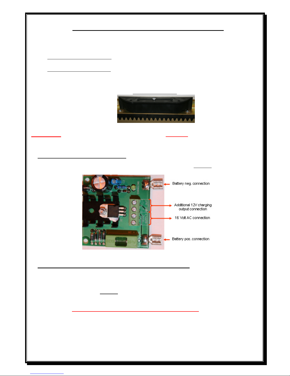
Low voltage Plug in transformer.
Connect 16volt AC from the transformer to the charger board marked as 16 VAC supply.
Low voltage on board (OBT) transformer – 220V at gate.
Connect 220V AC to input side of Eco500/16volt AC transformer (black & brown wires), or to
NEL (Neutral/Earth/ Live) connector on side of transformer, then connect the output wires (red) to
the charger board marked as 16 VAC supply.
DO NOT CONNECT 220V DIRECTLY TO PCB
WHEN 220V IS USED AT GATE MOTOR, A SEPARATE DOUBLE POLE ISOLATOR MUST
BE FITTED WITHIN 1METER FROM THE MOTOR.
 Loading...