

Page 1

Film-Tech
The information contained in this Adobe Acrobat pdf
file is provided at your own risk and good judgment.
These manuals are designed to facilitate the
exchange of information related to cinema
projection and film handling, with no warranties nor
obligations from the authors, for qualified field
service engineers.
If you are not a qualified technician, please make no
adjustments to anything you may read about in these
Adobe manual downloads.
www.film-tech.com
Page 2

DTS Timecode Preamplifier
Model E376
Installation and Operation Manual
October 25, 2001
(Manual P/N 9301E37600A)
www.dtsonline.com
DTS Europe Digital Theater Systems, Inc. DTS Japan
Digital Theater Systems (UK) Ltd. 5171 Clareton Drove AT Communications KK
Unit 5, Tavistock Industrial Estate Agoura Hills, CA 91301 USA 2-14-4 Shinonome, Koto-ku
Ruscombe Lane, Twyford Tel: (818) 706-3525 or (800) 959-4109 135-0062 Tokyo, Japan
Berkshire RG10 9NJ UK Fax: (818) 706-1868 Tel: +81(0)3 5564 7156
Tel: +44 1189 349199 Email: cinematech@dtsonline.com Fax: +81(0)3 3520 1022
Fax: +44 1189 349198
Email: dtsinfo@dtsonline.co.uk
Email: asano@dtsterch.com
(Liaison Office)
Page 3

DTS Timecode Preamplifier DTS Model E376
DTS Timecode Preamplifier
Model E376
TABLE OF CONTENTS
Section
INTRODUCTION ………………………………………………………………………….. 2
DTS 16MM ………………………………………………………………………………… 2
SPECIFICATIONS ………………………………………………………………………… 2
FRONT PANEL ……………………………………………………………………………. 3
REAR PANEL …………………………………………………………………………….. 4
(Internal) CIRCUIT BOARD, E326 ……………………………………………………… 5
PHYSICAL DIMENSIONS ………………………………………………………………. 6
INSTALLATION PROCEDURE …………………………………………………………. 6
INSTALLATION DIAGRAMS …………………………………………………………… 7
SYSTEM TEST ……………………………………………………………………………. 12
OPERATION ………………………………………………………………………………. 13
TROUBLESHOOTING ……………………………………………………………………. 13
DTS TECHNICAL SUPPORT …………………………………………………………… 13
REPLACEMENT PARTS LIST ……………………………………………………..…… 14
APPENDIX A: BLINKING DTS TIMECODE READER LED ……..………………. 15
Page
TC2 Signal Routing …………………………………………………………………………….. 4
Internal Jumpers ………………………………………………………………………………... 5
Diagram of Checking DTS Timecode With an Oscilloscope …………...……………………… 17
Page 1 of 18
Page 4

DTS Timecode Preamplifier DTS Model E376
INTRODUCTION
The E376 is an accessory to the DTS system and is designed to optimize the readability of DTS
timecode that is not recorded in the standard manner. Typically, DTS timecode is recorded with
a DTS exposure head and printed on either 35mm or 70mm film. These tracks are easily read
with the standard DTS timecode reader head (
TCRH
). However, when DTS timecode is
recorded on videotape or any other media, there is potential for readability problems such a loss
of low frequency or incorrect level. The E376 is able to optimize any DTS timecode source for
flawless playback in a DTS digital system when the use of a DTS timecode reader is impractical.
DTS 16MM
When using the DTS system with 16mm film, the standard optical sound track is not printed on
the film. Instead, DTS timecode is printed in the optical sound track area and read by the
projector’s standard optical head. Just like DTS 35mm film, the soundtrack is contained on DTS
CD-ROM
s and played on a DTS player. For DTS 16mm film, the E376 is standard equipment
and is designed to be a permanent install. The E376 allows you to change between standard
16mm optical and DTS digital playback.
Generally, the audio output of the projector is sent directly to the cinema processor for
distribution in the auditorium. The E376 is installed between the projector’s sound optics and
the DTS player. For DTS playback, the E376 is switched into the Active Mode. This mode
“conditions” the timecode from the 16mm optical sound head and routes it to the DTS player.
“Conditioning” of the timecode includes adding a low frequency boost, if needed, and ensuring
an output of 4-volts peak to peak. When the E376 is switched into the Bypass Mode, the
standard optical signal is routed directly to the cinema processor without any loading on the
audio line.
SPECIFICATIONS
J1 and J2 source inputs are typically from the projector’s sound head at either cell or line level.
There are dedicated connectors for up to two projectors (or sources). JP2 & JP3 jumpers on the
E326 board must be set for the input level (“
CELL IN
y Cell input is from 7mV to 200mV RMS.
y Line level input is from 240mV RMS to 7.74V RMS
” or “
LINE IN
”).
Power input is 5V DC and comes in at J4 when connected to the DTS digital player’s
TIMECODE connector(s). Pin-outs for the timecode cable is shown on D477 (page 14).
J1 and J2 signal outputs are typically connected to the cinema processor. When in “BYPASS”
the J1 & J2 source inputs are routed directly to this output. When “ACTIVE”, there is no output
at these connectors (to ensure that timecode signal is not heard in the auditorium).
Timecode signal output connects to the timecode input of the DTS player. When in “BYPASS”,
the TCRH input(s) is sent directly to this output. When “
ACTIVE
”, the conditioned timecode
signal from J1 & J2 is sent to the DTS player.
Physical Dimensions
y Height: 1.75” = one rack unit (
y Depth: 6” (
15.24cm
) y Weight: 1.70 Lbs. (
) y Width: 19” (
4.45cm
48.26cm
) rack mount
)
0.77kg
Page 2 of 18
Page 5

DTS Timecode Preamplifier DTS Model E376
FRONT PANEL
TIMECODE Illuminates green when good timecode is detected.
SIGNAL SOURCE Illuminates yellow when timecode signal is detected and
1 - 2 displays which projector is delivering the signal.
LOW Push-button switch.
FREQUENCY y Press “IN” when a low frequency boost is required to read timecode
COMPENSATION y Press
“OUT
” when a boost is not needed to read good timecode
The use of this switch greatly depends on the frequency range of the
output signal from optical sound preamplifier (if used). If the signal is
rolled off below 200Hz, a low frequency boost is required for good
timecode to be read.
PREAMP “
(
s) “
L.E.D.
ACTIVE
BYPASS
” illuminates blue when the E376 preamplifier is active.
” illuminates green when the E376 preamplifier is bypassed.
PREAMP Push-button switch.
(switch) y Press in to select “
ACTIVE
”. Activates the E376 preamplifier and the
input signal(s) from J1 & J2 are “conditioned” and sent to the TC out
connector(s).
y Press out to select
“BYPASS”.
When in Bypass mode, the input signals
are connected directly to the J1 & J2 outputs.
Page 3 of 18
Page 6
DTS Timecode Preamplifier DTS Model E376
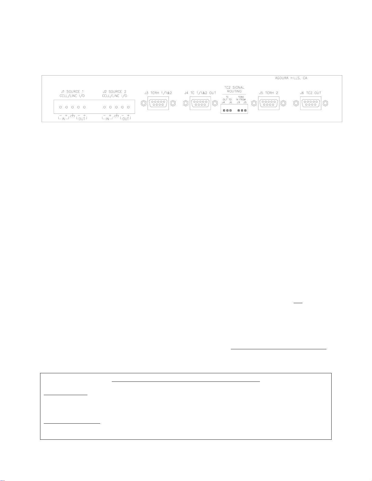
REAR PANEL
CELL/LINE I/O
These in/out terminals provide a balanced input connector for DTS timecode
(J1 & J2) sources. They also provide loop through output to a cinema processor or mixing
board. JP2
level (“
CELL IN
y Cell input is from 7mV to 200mV RMS.
y Line level input is from 240mV RMS to 7.74V RMS
JP3 jumpers on the E326 board must be set for the correct input
&
” or “
LINE IN
”).
TCRH 1/1&2 This input is dedicated to DTS timecode reader heads, which are installed on
(J3)
.
35mm & 70mm film projectors. When two projectors are being used for changeovers, a “Y” cable must be used to feed both signals to this input. When the
E326 is in “
BYPASS
TC1/1&2 OUT.
”, this signal is routed directly to the DTS player via the
TC 1/1&2 OUT This output connects directly to a DTS player when using (1) a single projector
(J4) -or- (1&2) two projectors using a timecode “Y” cable. When two projectors
TCRH 2
(
change-over
pin 1 and Proj2 TC IN must be on pin 2 of the player’s “
This input is dedicated to DTS timecode at a second projector when not using a
) are being used with DTS-6/-6D players, Proj1 TC IN must be on
TIMECODE
” connector.
(J5) “Y” cable. It allows the timecode signal from the reader to pass through the
E376 to the DTS-6AD when the “
PREAMP
” switch is set to “
BYPASS
”.
TC2 OUT This output is dedicated to DTS timecode at a second projector and connects
(J6) directly to a DTS-6AD “
own dedicated timecode reader and cable – the DTS “Y” cable cannot be used
The DTS-6AD needs to see TC for Proj2 on pin 1 of “
and TC for Proj1 on pin 1 of “
PROJ 2 TC
” input. It is used when each projector has it’s
” connector
PROJ 1 TC
PROJ 2 TC
” connector.
“TC2 SIGNAL ROUNTING” jumper selections
“TC OUT TO”
“J4” Routes Proj2 source signal to DTS-6/-6D player “
“J6” Routes Proj2 source signal to DTS-6AD “
PROJ 2 TC
TIMECODE
” input on pin 1
” input on pin 2
“TCRH IN FROM”
“J3” Takes TCRH #2 input signal at J3 (
“J5” Takes TCRH #2 input at J5 (
from single timecode cable
from timecode “Y” cable
) on pin 2 (
) on pin 1 (
for DTS-6/-6D
for DTS-6AD)
)
.
Page 4 of 18
Page 7

DTS Timecode Preamplifier DTS Model E376
(Internal) CIRCUIT BOARD, E326
Internal Jumpers
JP1 Used to tie power ground and chassis ground together. The jumper is normally
connected.
JP2 This jumper needs to be set by the installer to match the timecode signal input level of
J1. Choices are “LINE IN” or “CELL IN”. See
SPECIFICATIONS
for details.
JP3 This jumper needs to be set by the installer to match the timecode signal input level of
J2. Choices are “LINE IN” or “CELL IN”. See
SPECIFICATIONS
for details.
Page 5 of 18
Page 8

DTS Timecode Preamplifier DTS Model E376
INSTALLATION PROCEDURE
Use the installation procedure that matches the existing projection and sound equipment. It is
assumed that a six-channel cinema processor, speakers, amplifiers, and a DTS digital player are
part of the cinema sound system.
1. Set internal jumpers on E326 board, JP2 & JP3. You must first determine the input lvel
2. Mount the E376 in the sound rack. Keep within 6 feet of the DTS player.
of the DTS timecode audio on J1/J2:
y A “cell level” output is from 7mV to 200mV
JP2
JP3 to “Cell In”.
&
y A “line level” output is from 240mV to 7.74V
JP3
JP4 to “Line In”.
&
. For cell level, set the internal jumpers at
RMS
For line level, set the internal jumpers at
RMS.
3. Connect the timecode source to J1/J2 inputs. If the timecode source is a 16mm projector
and the sound head is already connected to a cinema processor, it is necessary to break
this connection.
y Observing polarity, connect the audio/optical lines from the projector to the E376 J1 input
connections: “
CELL/LINE I/O (1)”
y Matching the input polarity, connect the audio/optical lines from the cinema processor to the
J1 output connections: “
E376
y Repeat I/O connections on J2 if a second projector is used.
4. Disconnect the existing timecode cable from rear of the DTS player and instead:
y For the DTS-6/-6D, connect TCRH cable (
y For the DTS-6AD, connect Proj1 TCRH cable to E376 J3, “
second projector is used, connect it’s TCRH cable to E376 J5
5. Connect the timecode out cables supplied with the E376:
y For the DTS-6 or DTS-6D, connect cable from player’s
“
TC 1/1&2 OUT
” connector.
y For the DTS-6AD, connect cable from player’s “
connector. If a second projector is used, connect the second cable from player’s “
J6 “
E376
6. Set the E376 rear panel “TC2 SIGNAL ROUTING” jumpers:
TC 2 OUT
y For the DTS-6/-6D, set “
middle pin and “J3”.
y For the DTS-6AD, set “
” connector.
TC OUT TO
TC OUT TO
middle pin and “J5”.
7. If this is a new DTS installation and two projectors are used with the DTS-6/-6D, verify the payer
is programmed for “change-over” operation. See player manual.
at “IN +” and “IN-“.
CELL/LINE I/O (1)”
single or “Y”)
at “OUT +” and “OUT –“.
to E376 J3, “
connector.
TIMECODE
PROJ 1 TC
” for middle pin and “J4”, and set “
” for middle pin and “J6”, and set “
TCRH 1/1&2
TCRH 1/1&2
” connector. If a
connector to E376 J4,
” to E376 J3, “
TC IN FROM
TC IN FROM
” connector.
TCRH 1/1&2
PROJ 2 TC
” to
” for
” for
”
Page 6 of 18
Page 9

DTS Timecode Preamplifier DTS Model E376
INSTALLATION DIAGRAMS
Page 7 of 18
Page 10

DTS Timecode Preamplifier DTS Model E376
Page 8 of 18
Page 11

DTS Timecode Preamplifier DTS Model E376
Page 9 of 18
Page 12

DTS Timecode Preamplifier DTS Model E376
Page 10 of 18
Page 13

DTS Timecode Preamplifier DTS Model E376
Page 11 of 18
Page 14

DTS Timecode Preamplifier DTS Model E376
Page 12 of 18
Page 15

DTS Timecode Preamplifier DTS Model E376
SYSTEM TEST
This assumes that the cinema processor and DTS player have been correctly calibrated.
1. Use the installation diagram (
pages 7-12
Verify the E376 is properly installed and that the internal JP2
(
page 2, “J1/J2
INPUTS
”).
2. If two-projectors are used, verify “
See Table page 5.
3. Power on the sound rack. Verify the cinema processor, speaker amplifiers, DTS player are all
powered. Verify one of the E376 front panel “
it’s power (5 volts DC) from the DTS player (timecode connector).
4. Set the E376 “
5. Set “
LOW FREQUENCY COMPESTATION
PREAMP
” switch to “
6. Cue the DTS timecode source machine. If using DTS 16mm film, thread the projector. The film
must have DTS timecode where the optical (analog sound) track normally resides.
7. Load the matching discs into the DTS player. Wait for the DTS player to fully boot up (the
player’s
SYSTEM
light will flash)
8. Run the timecode source machine or start film. While the E376 is in the Active mode, timecode
is being read at J1/J2. If the “
FREQUENCY COMPESTATION”
stays on.
y The DTS player’s “
TIMECODE
TIMECODE
automatically playing the DTS digital sound track (
have automatically pulsed to the DTS digital format.
9. Verify the E376 “
SOURCE SIGNAL
10. The DTS player should be playing the disc(s) and the DTS digital sound track should be heard
playing in the auditorium.
11. If there are two timecode sources (
12. Put the E376 in Bypass Mode and perform the following tests:
y If the loop through is used at J1/J2 inputs, run the timecode source machine wired to J1/J2
inputs. Preferably, with an audio track instead of timecode, to confirm the signal is being
looped.
y Next, run the 35mm or 70mm projector with standard timecode and confirm that the timecode
light on the DTS player comes on.
13. When playing the standard 16mm, 35mm, or 70mm format, make certain the E376 is in the
Bypass Mode.
) that matches the equipment required for the installation.
JP3 jumpers are correctly set
&
TC2 SIGNAL ROUTING
PREAMP”
ACTIVE
”. The “
” rear panel jumpers are correctly set.
lights are illuminated. The E376 gets
ACTIVE
” blue light should be illuminated.
” switch to “OFF”.
” light does not illuminate, switch “ON” the
. Leave the switch in this position if the “
TIMECODE
” light should illuminate. The DTS player should be
on discs
) and the cinema processor should
” yellow light illuminates to indicate sufficient signal level.
change-over
), repeat test for the second source.
“LOW
” light
Page 13 of 18
Page 16

DTS Timecode Preamplifier DTS Model E376
OPERATION
When playing the standard 35mm or 70mm DTS format, make certain the E376 is in the Bypass Mode.
This allows the existing DTS timecode reader(s) to connect to the DTS player. Also, for 16mm
applications, allows the standard optical track to pass through the E376 without any loading on the line.
When using the E376 preamplifier to read timecode from a source other than standard DTS readers, set
the “
PREAMP
” switch to “
ACTIVE
”. This switches the E376 in circuit and routes J1 & J2 inputs to the
DTS player.
Be sure to leave the “
LOW FREQUENCY COMPENSTATION
” switch in the position selected during
installation. It is used when the timecode input on J1/J2 rolls off the low frequencies.
TROUBLESHOOTING
No lights on E376
y Verify the DTS player is powered. Use a volt meter to verify +5V DC on pin 5 (
TIMECODE
cable from the DTS player.
ground is pin 6
y Verify the timecode cable wires are not shorted or broken.
E376 “
TIMECODE”
y Verify the E376 “
light does not illuminate
PREAMP
” switch is set for “
ACTIVE
” and the blue “
ACTIVE
” light is illuminated.
y Verify DTS timecode is on the J1/J2 inputs. For 16mm, visually inspect the film for timecode. (DTS
16mm formatted film has the timecode track placed where the mono track normally resides).
y Verify all timecode connections.
y If the E376 is in the Active mode, try switching the “
LOW FREQUECNY COMPENSTATION
) on the
” switch.
DTS player will not play DTS digital sound track.
y If running film with DTS timecode located where the optical sound track normally resides, verify the
E376 “
PREAMP
” switch is in the Active mode.
y If running standard 35mm (with optical sound and DTS timecode tracks) verify film is threaded
through the DTS reader(s) and that the E376 is in the Bypass mode.
y Be sure the show discs are loaded into the DTS player and the player is fully booted up.
y If the “
TIMECODE
” lights are blinking, see Appendix A (
page 18
) for troubleshooting help.
Second projector isn’t working
y If no 16mm optical sound, verify wiring of the second projector at J2. E376 must be in Bypass Mode.
y If no timecode, verify the DTS-6/-6D is set for change-over. Verify E376 “TC2” jumper settings.
No 16mm optical sound
y Verify the E376 “
PREAMP
y Verify the optical/cell wiring is correct and all wires are intact. See installation diagrams, pages 7-12.
y Verify the (
projector’s
” switch is set for “
BYPASS
) exciter lamp is powered.
” and the “BYPASS” light is illuminated.
DTS TECHNICAL SUPPORT
TELEPHONE: (800) 959-4109 or (818) 706-3525 FAX: (818) 879-2746
DTS engineers are available to assist you. If an emergency occurs after business hours, please leave a
message with the answering service. Your call will be returned as soon as possible.
INTERNET users may email DTS Technical Support at: cinematech@dtsonline.com
DTS Web Site
http://www.dtsonline.com
Page 14 of 18
Page 17

DTS Timecode Preamplifier DTS Model E376
REPLACEMENT PARTS LIST
For single projector or DTS-6AD
9-pin male D-conn. both ends
2503 0019 00
6 ft. Timecode Cable
D435-01 30 ft. Timecode Cable standard
D435-02 4
D435-05
0 ft. Timecode Cable
45 ft. Timecode Cable
D435-06 60 ft. Timecode Cable
9-pin male D-conn. to bare wires
E434
Mono Input Cable for DTS-6AD (one cable per projector)
For dual projectors and DTS-6 or DTS-6D
9-pin male D-conn. all ends
D435-08
Timecode Y Cable, 20ft. / 30ft. standard.
D435-09 Timecode Y Cable, 40 ft. / 50ft
D435-10 Timecode Y Cable, 60 ft. / 60 ft.
DTS Timecode Reader Heads
D600-00
DTS Timecode Reader Head, 35mm
E108 Auxiliary Roller assembly kit, 35mm
D600-02 DTS Timecode Reader Head, 70mm
Auxiliary Roller assembly kit, 35mm
E163
Miscellaneous
2011 1X05 00 Terminal Block, 5-position, 5.08 spacing
2006 1X02 00
2-position shunt (jumper)
Page 15 of 18
Page 18

DTS Timecode Preamplifier DTS Model E376
APPENDIX A: BLINKING DTS TIMECODE READER LED
The timecode reader LED should remain bright and not flash more than a few times a minute. Excessive
flashing indicates a problem and should be fixed as soon as possible. The optics on the reader should be
blown off with compressed air at least once a day, but never adjust the lens.
Excessive blinking can cause drop-outs (if the 4-second flywheel is exceeded). Drop-outs can produce
wow, edits, and repeated sound track.
There are four things that can cause the reader LED to blink:
1) Bad/poor timecode. This is usually limited to a single reel or trailer, and is encountered
infrequently. If seeing bad reels regularly, check for other problems.
2) Film instability/speed. This is caused by film bouncing through the reader or a projector that is
running at the far end of the DTS player’s speed range. The reader requires some film backtension to read properly.
3) Electrical noise/grounding problems. One cause it the projector’s chassis not being earth
grounded.
4) DTS equipment problem. This is caused by either the reader or the player. If another reader can
be borrowed from a working screen, try swapping.
Bad/Poor Timecode
See “DTS Encoded Film” specifications at the end of Section 7.
Film Instability/Speed
• Check the speed of the projector. It should run at 24 fps +/-5%.
• Make sure the reader’s auxiliary roller (back with an adjustable arm) is installed and provides as much
wrap as possible on the incoming silver roller. It should be pivoted towards the cable end of the reader
and be back as far as possible.
• Watch the film run through the reader. If aligned properly, the film should contact each side of the
roller evenly.
• Gently squeeze the edges of the film between two fingers as it enters the reader, pull back slightly and
allow your fingers to act as shock absorbers. Repeat on the exit side of the reader. If the LED
stabilizes, try to find the source of instability. The following are possible sources of instability:
• Poor reader alignment
• Too much tension
• Bad rollers(s)
• Bad platter center piece
• Bad projector belt, gear, or sprocket
• Bent reel
• Too little tension
• Reel clutch
• Platter center piece spring removed (AW-3)
Page 16 of 18
Page 19

DTS Timecode Preamplifier DTS Model E376
Electrical noise/grounding problems
• Electrical noise on the timecode input(s) can confuse the timecode reader circuit. This causes the LED
to blink and, in some cases, cause sound wow, edits, and dropouts. First, make sure the projector(s) and
the DTS chassis are earth grounded.
• The current reader cables (from the DTS factory) have a shield wire shrink-wrapped to the cable’s
jacket, on the reader end. Cut the shrink-wrap away and connect the wire to one of the screws that hold
the reader to its bracket. Check for any change in operation.
• If you have made your own cable or modified the factory cable in any way, be sure the shield is
connected to the conductive connector shells at both ends.
• Do not run the timecode cable along power lines, over florescent light fixtures, or near motor
controllers. Cable must be shielded.
• If the timecode reader-head board is Rev. F or lower, replace the reader with a newer revision board.
The board revision can be viewed by tilting the reader and looking just below the 9-pin connector.
DTS equipment problem
• Borrow a known good reader from another screen. If this fixes the problem, replace the reader.
• Check the timecode cable. Verify continuity and physical integrity.
• Check firmware inside the player.
Page 17 of 18
Page 20

DTS Timecode Preamplifier DTS Model E376
Checking DTS Timecode with an Oscilloscope
Connect option 1 Remove the timecode reader cable’s connector shell from the reader end.
Connect the scope probe to Pin 1 and the scope ground to Pin 6.
Connect option 2 If using the “DTS timecode reader to oscilloscope adapter” (DTS P/N
D929), simply disconnect the timecode cable from the reader head.
Connect the adapter to the reader head (male DB9) and connect the
timecode cable to the other end of the adapter (female DB9). Then,
connect the BNC to the oscilloscope.
Set the scope to 0.5V/division, sweep at 0.5mS/division, and the trigger to internal.
Run a reel of time-coded film (BILL AND BUZZ reel preferred) and observe the timecode cells.
The amplitude should be constant, and approximately 4 Volts Peak-to-Peak. The cells should be
visible all the way to the right of the scope screen. The cross-points (“X”s) should be well
defined (FIG. 1). Poorly defined cells are shown in FIG. 2. They are caused by film bounce and
jitter through the projector or from the platter/reel.
FIG. 1 GOOD TIMECODE FIG. 2 POOR TIMECODE
500mV/DIV .5mS/DIV 500mV/DIV .5mS/DIV
Page 18 of 18
 Loading...