

Page 1
1
Base plate-mounting instructions
E-EEEE
DTS 512/624 (Sentry PCB)
SLIDING GATE MOTOR
INSTALLATION MANUAL
DTS SECURITY
P.O.BOX 3399
EDENVALE
1610
TELEPHONE 086 1000 387
Spartan +2711 392 5540 (H/O)
Pretoria +2712 548 2336
Alberton +2711 907 8846
www.dtssecurity.co.za
Page 2
2
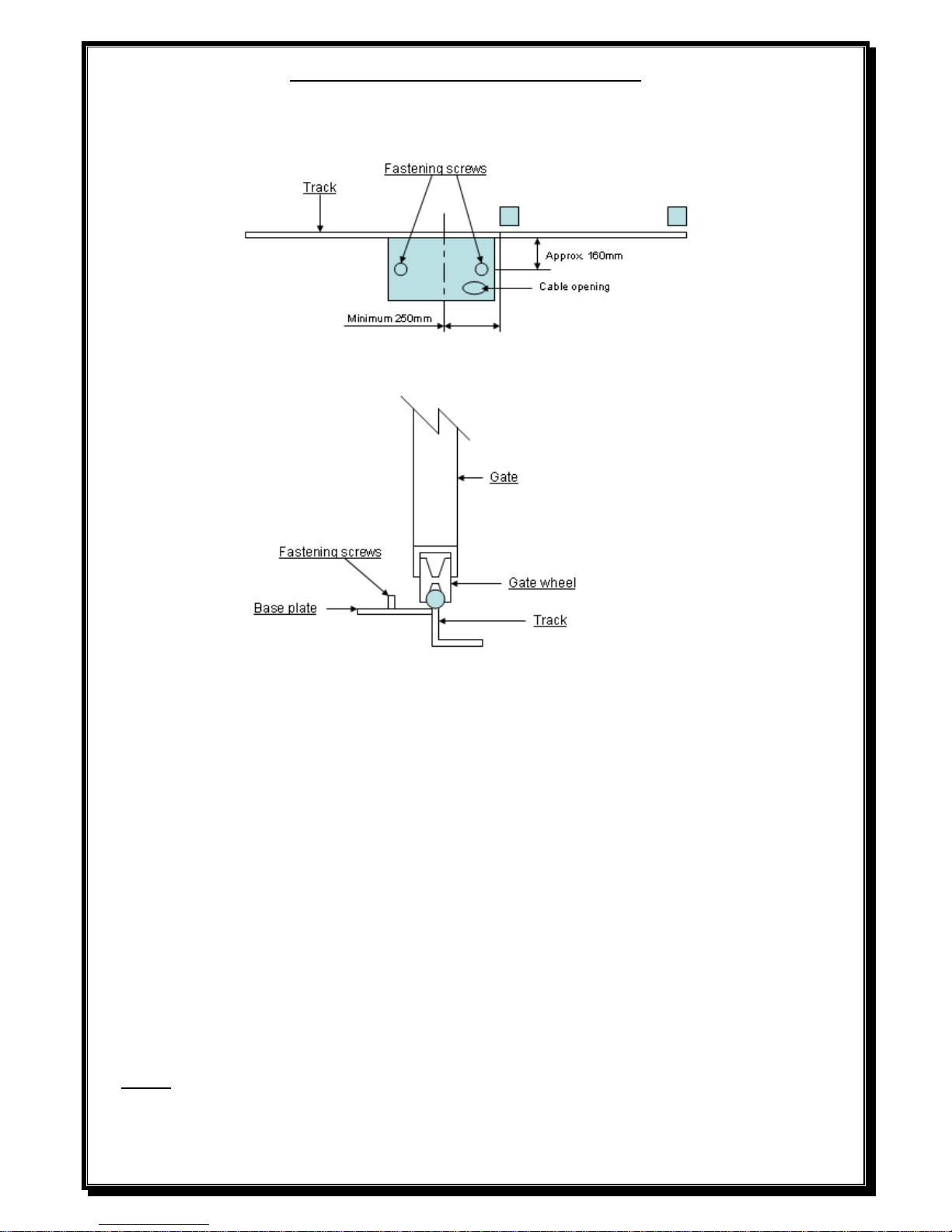
BASE PLATE MOUNTING INSTRUCTIONS
1. Assemble base plate by fastening M10x30 Hex set screws into base plate from under
the base plate up and tightening into position.
2. Mount base plate with bolts 160mm from the centre of the gate track and centre of base plate a
minimum of 250mm away from the gate opening.
3. Secure the base plate to the gate track by welding the base plate directly to the gate track. (Ensuring a
distance of 160mm from centre of gate track to centre of fastening screws).
4. Fit all required cabling through hole provided in base plate.
5. Support the back of the base plate with 40x40x3 angle iron (not provided) or similar off cut steel
knocked approximately 300 to 400mm into the ground.
6. Fill area below and around the base plate with approximately 300x400x300 concrete to ensure that the
motor will be secure.
7. NOTE - The DTS 624 motor must be fitted with a set of IR beams.
Page 3
3
Gearbox mounting instructions
1. Fit gearbox over mounting bolts protruding from base plate.
2. Slide gate fully open and closed, insuring pinion gear has approximately 5mm clearance to gate at all
times.
3. Fasten gearbox down firmly to base plate using M10 washers and nuts.
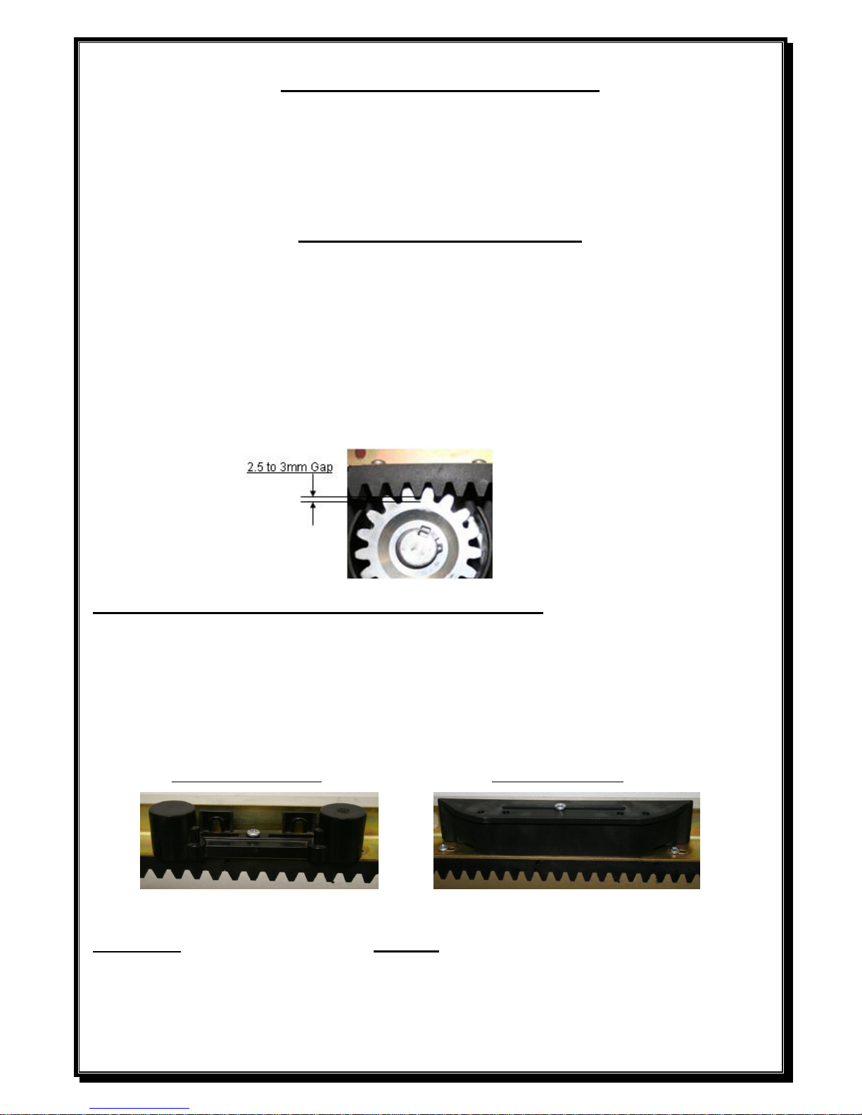
Rack mounting instructions
1. Unlock and pull manual override lever fully out to disengage gearbox.
2. Using a 2,5 to 3mm spacer between the pinion gear and the rack, mount the rack
using Tek screws No12x20 (not provided) and screw the rack to the gate starting
from the tail of the gate and ensuring that the rack is mounted level.
(A spacer can also be put between motor and base plate when fitting rack).
NB: Ensure that one of the screws attaching the nylon rack to the angle is in line with the
limit switch spring when the gate is fully closed.
Limit switch actuator mounting instructions
1. Remove screw attaching the nylon rack to angle that is closest to the position that
you wish the gate to stop.
2. Fit limit switch actuator with screw provided, screwing into the nylon rack.
3. Adjust limit switch actuator so that the gate stops approximately 10mm before
the post.
Magnetic limit actuator Spring limit actuator
Important: A solid stop must be fitted at both ends of the gate to prevent the gate from moving past its
full open or close position.
Page 4
4
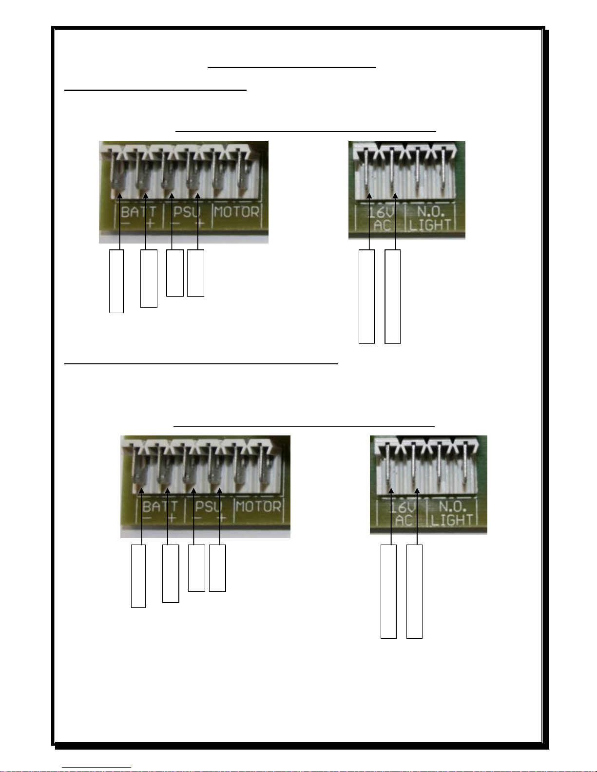
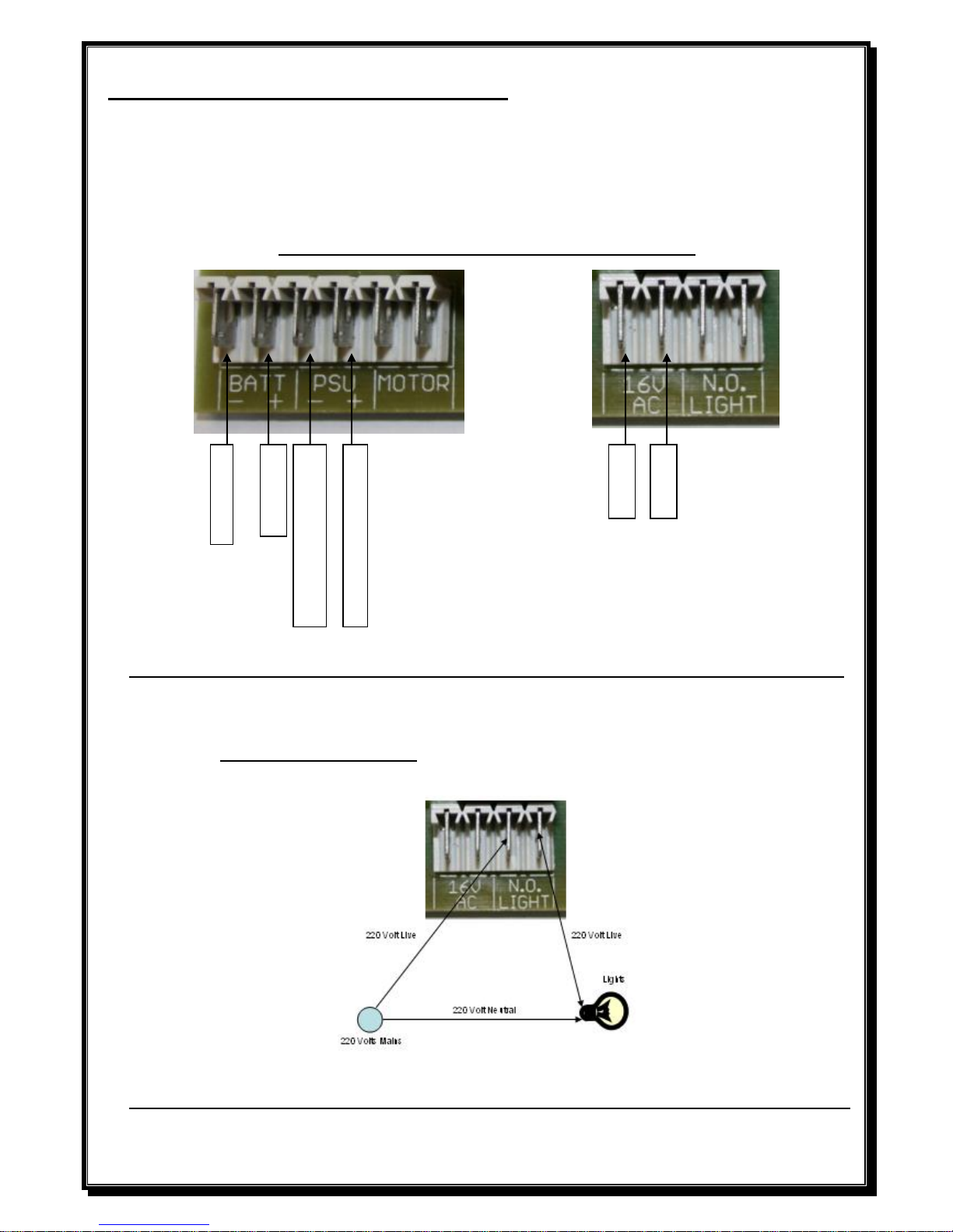
POWER CONNECTIONS
Low voltage Plug in transformer.
Connect 16V AC connectors on plug in transformer to 16V AC connectors on controller card.
DO NOT CONNECT 220V DIRECTLY TO PCB
Low voltage on board transformer – 220V at gate.
Connect 220V AC to input side of 16V AC transformer (black & brown wires), connect output
wires (red) to16V AC connectors on controller card.
DO NOT CONNECT 220V DIRECTLY TO PCB
IF 220V IS USED AT GATE MOTOR, A SEPARATE DOUBLE POLE ISOLATOR MUST
BE FITTED WITHIN 1M FROM MOTOR.
BAT (-) BLACK
BAT (+) RED
NOT USED
NOT USED
16 VAC from transformer
16 VAC from transformer
BAT (-) BLACK
BAT (+) RED
NOT USED
NOT USED
16 VAC from transformer
16 VAC from transformer
Page 5
5
High access power supply unit – 220V at gate.
Connect 220V AC to LEN (Live/Earth/Neutral) connector on side of power supply unit.
Black lead from power supply unit gets connected to – ( neg.) PSU connection on Pcb.
Red lead from power supply unit gets connected to + ( pos.) PSU connection on Pcb.
DO NOT CONNECT 220V DIRECTLY TO PCB
DO NOT USE POWER SUPPLY UNIT (PSU) AND LOW VOLTAGE TRANSFORMER (16V AC) TOGETHER.
IF 220V IS USED AT GATE MOTOR, A SEPARATE DOUBLE POLE ISOLATOR MUST
BE FITTED WITHIN 1M FROM MOTOR.
COURTESY LIGHT OUTPUT (Will stay on for 3 minutes after a trigger is received)
DO NOT CONNECT 220V DIRECTLY TO PCB UNDER ANY CIRCUMSTANCES.
BAT (-) BLACK
BAT (+) RED
NOT USED
NOT USED
(-) DC Voltage from transformer
(+) DC Voltage from transformer
Page 6

6
DO ALL RUNTIME AND TRANSMITTER PROGRAMMING BEFORE CONNECTING ANY ADDITIONAL
INPUTS SUCH AS, –INTERCOM, BEAMS ETC.
NOTE- IR beams must be fitted if DTS 624 motor is installed.
DO NOT CONNECT 220V DIRECTLY TO PCB
Dipswitch selections to activate a function.
Dipswitch 1 - Programming.
2 - Motor direction. (This can only be changed before programming or if neither limit
switches are activated).
3 – Auto close.
4 – Condominium mode.
5 – P.I.R.A.C. mode
6 – Slow down distance change
Dipswitch selection for programming. (With dipswitch 1 ON)
Dipswitch 3 – Auto close. (Infra red beams must be fitted if auto close is activated).
Dipswitch 4 – Pedestrian (Distance and time).
Page 7

7
PROGRAMING
1 – Run Time Setup (This will automatically happen when triggered after total power up or
by following the steps below).
Gate approximately 1metre open
With all dipswitches OFF (excluding dipswitch 2 pending motor direction), press & release
Bt/SET button.
Gate will close, open and close again and stop on close limit (Motor speed can be increased
during programming of open cycle by pushing and holding down the Bt/SET button). The
closing cycle of programming will automatically run at fast speed.
Control card will beep to confirm end of run time setup.
NOTE: If gate opens first, dipswitch number 2 is wrongly selected.
2 – Auto close (Default 15 seconds) (Infra red beams must be fitted if auto close is activated).
Switch Dipswitch 1 and 3 ON.
Press & hold Bt/SET button
PCB will Beep (1 Beep = 1 Sec)
Release Bt/SET button at required auto close time.
Switch Dipswitch 1 and 3 OFF.
Switch Dipswitch 3 back ON to activate the auto close.
3 – Pedestrian Opening (Default 1 meter / 4 seconds auto close)
Switch Dipswitch 1 and 4 ON.
Gate should be in closed position.
Press & Release Bt/SET Button.
Gate will open.
Press & release Bt/SET button to stop gate at required pedestrian opening distance.
Press & Hold Bt/SET button to program auto close time required.
Control card will Beep (1 Beep = 1 Sec)
Release Bt/SET button at required pedestrian auto close time.
Gate will close again.
Switch Dipswitch 1 and 4 OFF.
To reset factory default, push and release Bt Lrn or Pd Lrn, then press and hold Bt/SET for
approximately 5 seconds, the PCB will give 2 short beeps as acknowledgement.
Page 8

8
Load setting
To adjust the load, turn the provided load pot very slowly to determine the load setting (Minimumanticlockwise & Maximum clockwise). The control card will beep as you turn the pot (1 - 5 beeps).
ON BOARD RECEIVER PROGRAMING
The onboard receiver is designed to work with Sentry rolling code transmitters.
The button used for Bt Lrn CANNOT be used for Pd Lrn and vice versa.
To erase a button from the receiver, in case of incorrect programming i.e. blue button should be for Bt Lrn
and not Pd Lrn.
Simply push and hold the Bt Lrn or the Pd Lrn for 5 seconds, the board will give 1 beep. Then push the button you
want to erase, the board will give 2 beeps as confirmation. That button is then erased and can be relearned into the
correct input.
To master erase:
Push and hold the Bt Lrn or the Pd Lrn button, after 5 seconds the board with give 1 beeps. Keep holding for
another 5 seconds then the board will give 2 beeps. All transmitters will now be erased.
PROGRAMMING A
TRANSMITTER FOR FULL
OPEN OPERATION –Bt Lrn
PROGRAMMING A
TRANSMITTER FOR PEDESTRIAN
OPERATION-Pd Lrn
1. Push the Bt Lrn button, the
RX led will go on.
2. Push the required button on
the transmitter, the board
will give 2 beeps.
3. Repeat Step 1 and 2 for
additional transmitters. Up to
25 transmitters can be
programmed for this
operation.
1. Push the Pd Lrn button, the
RX led will go on.
2. Push the required button on
the transmitter, the board
will give 2 beeps.
3. Repeat Step 1 and 2 for
additional transmitters. Up to
5 transmitters can be
programmed for this
operation.
Page 9

9
ELECTRONICS
FEATURES:
1. Standard
2. Easy motor direction change
3. Auto close facility (Infra red beams must be fitted if auto close is activated).
4. Condominium / Free exit loop facility
5. P.I.R.A.C (Passive Infra Red Access Control) facility
6. Slowdown (Ramp down) facility
1. Standard Mode (No function selected)
When the gate is activated it will open and can be stopped in mid cycle by pressing the
transmitter or manual push button. Pressing the transmitter or push button can reverse the
gate. In standard mode the gate will remain on its open limit until it is triggered to close.
If main power fails, the motor will still operate until battery reaches 20 volt. Gate will then
remain close. Change to manual by overriding the motor by the override lever. When the
main power comes on again, lock in the override lever and the motor will function as
normal.
2. Easy motor direction change (Dipswitch 2)
By selecting the dipswitch, the motor direction and the limit wires are changed
automatically. Dipswitch ON, gate closes to the right. Dipswitch OFF, gate closes to the left.
(This can only be changed before programming or if neither limit switches are activated).
3. Auto close (Dipswitch 3 ON) (Infra red beams must be fitted if auto close is activated).
When Auto close is activated and the Gate opens to the open limit, the gate will wait the
pre-programmed time before automatically closing. If the gate is triggered while the gate is
in its closing cycle it will stop and reopen.
To override the auto close wait till the gate reaches its open limit then press & hold the
transmitter or manual push button for 5 sec. (The control card will give 1 long beep to
confirm the override) To reactivate the auto close, press the transmitter or manual push
button.
If the transmitter or manual push button is pressed while the gate is in its opening cycle, the
gate will close after the preprogrammed auto close time (from any position, not only from
the open limit)
Page 10

10
4. Condominium/free exit loop (Dipswitch 4 ON)
When condominium/free exit loop is activated on the unit, the unit will not respond to any
transmitter or manual push button while in its opening cycle or open position. When the
gate is on the open limit the unit will automatically wait the pre-programmed auto close
time and then close (even if auto close function is not selected i.e. dipswitch 3 is off).When
the gate is in its closing cycle and the transmitter or manual push button is pressed the gate
will stop and open. Auto close cannot be over ridden in condominium mode. If main power
fails, the motor will still operate until battery reaches 20 volt. Gate will then remain open.
Change to manual by overriding the motor by the override lever. When the main power
comes on again, lock in the override lever and the motor will function as normal.
5. P.I.R.A.C (Passive Infra Red Access Control) (Dipswitch 5 ON)
With P.I.R.A.C mode activated, if the gate is in its opening cycle and the IR beam is
activated and released the gate will stop and close immediately. When the gate is on the
open limit the unit will not automatically close unless auto close has been selected.
6. Slowdown (Dipswitch 6)
With dipswitch selected ON, the gate will have a long close and open ramp down distance,
and with the dipswitch OFF, a short ramp down distance.
NOTE - (For any gate exceeding 3.5 meters width, the long ramp down is recommended).
FOR SAFETY REASONS
Infra red beams are recommended for all
gate motor installations.
Page 11

11
PCB Control card.
For PCB identification
2 x Voltage regulators = 24V motor.
1 x Voltage regulator = 12V motor.
NB – When connecting intercoms to the control card, please ensure that your intercom trigger output is
potential free (ZERO voltage). If not, a gate relay module must be fitted.
Page 12

12
TROUBLESHOOTING
SYMPTOMS
CAUSES
ACTION
When pressing the remote
transmitter the gate operator
will not respond at all
OR
PCB responds but gate will not
open
Transmitter battery flat.
Transmitter physically damaged.
Transmitter has not been
programmed into the receiver
memory.
Battery has reached its low level
(10/20 Volt) indicated by 3 beeps
/ 3 beeps.
Motor is in holiday lock-out,
indicated by 4 quick beeps.
Override door is open, indicated
by 3 short beeps.
PCB faulty, indicated by 1 long
and 1-5 short beeps.
Motor/Load Fuse blown,
indicated by the relays clicking
followed by 4 short beeps
Replace transmitter battery.
Check with supplier.
Follow the receiver setup
instructions.
Check the household main
supply, the transformer or PSU
and all related cabling.
Press and hold the pedestrian
remote for approximately 13
seconds. PCB will give 5 long
beeps to indicate holiday lock-out
is released.
Close override door.
Return PCB to supplier.
Replace the (12Volt) 25 Amp
Fuse, (24Volt) 10 Amp Fuse.
When pressing either the
transmitter or the PCB button
(Bt/SET), no movement or
opens a short distance only.
Not picking up the encoder
reader, indicated by a short
movement followed by 4 short
beeps.
Motor overload, indicated by a
short movement followed by 4
short beeps and the St LED
flashing fast.
Fix encoder reader position to the
magnet on the motor.
Turn up the load on the load pot.
Remove any obstructions from
the rail.
Check weight and pulling force of
gate.
Page 13

13
Before operating, the unit gives
two long beeps
The primary supply has failed
and the unit is running on battery
reserve.
Check the household main
supply, the transformer or PSU
and all related cabling.
The gate opens but will not
close
The primary supply has failed
and the unit is running on battery
reserve with the
condominium/loop option
selected and it has reached its low
battery limit (10/20 Volt)
indicated by 3 beeps / 3 beeps.
Safety infra-red beams are
obstructed or the beams
equipment/cabling are faulty.
Check the household main
supply, the transformer or PSU
and all related cabling.
Clear obstruction or
repair/replace safety infra-red
beams equipment/cable.
The gate when closing stops
and reverses or when opening
stops.
OR
Gate tries to run and the relays
kick out.
The unit is sensing an obstruction
The infra-red beam has been
triggered.
Another trigger has been received
by the control card.
Encoder is faulty.
Clear obstruction or adjust load
sensing.
Clear obstruction.
Check with other operators on the
system.
Turn ring magnet on the motor by
hand: if no activity on the
encoder LED, contact supplier.
Gate does not remain open.
Auto close has been selected.
Another user has triggered the
unit.
Condominium/loop has been
selected.
Deselect auto close or use auto
close override.
Deselect condominium / loop
mode.
When the beams input is
triggered, the gate stops and
reverses during opening cycles.
P.I.R.A.C. mode has been
selected.
Gate is closing in the wrong
direction.
Deselect P.I.R.A.C. mode
Dipswitch 2 is selected
incorrectly.
Page 14

14
The unit beeps 3 times and
opens partially, beeps 3 times
and the closes. This can
sometimes continue
indefinitely.
The pedestrian (Pd) mode is
being triggered. This is constant
if the sequence keeps repeating.
A transmitter code has been
programmed into the pedestrian
(Pd Lrn) function of the receiver.
Check with the other operators
and check switching equipment /
cabling attached to the (Pd) input.
Re-code the receiver as per
instructions
When gate reaches a limit
actuator, the unit does not stop
running.
Limit inputs wired incorrectly
(out of sync’ with the motor
direction.)
Limit switch is faulty.
Re-wire
Check with supplier.
Gate motor is jumping teeth on
the rack.
Pinion to rack spacing is
incorrect.
Rack is insufficiently fastened to
gate leaf.
Re-align.
Re-align and correct fastening.
Gate jams in the open or closed
position and is not easy to
manually release.
Gate is running too far.
Gate is running past its limit
actuator.
Adjust the limit actuators so that
the gate does not ram into the end
stops.
Replace the switch, rewire
correctly or check limit spring
assembly.
Page 15

15
Manufacturers warranty.
All goods manufactured by DTS Security carry a 12 month factory warranty
from date of invoice.
All goods are warranted to be free from faulty components and manufacture.
Faulty goods will be repaired or replaced at the sole discretion of DTS Security
Products, free of charge.
This warranty is subject to the goods being returned to the premises of DTS
Security Products.
This warranty excludes lightening damage, insect damage and damage caused
by faulty installation.
In the event of the goods being supplied by dealer, merchant, agent or duly
appointed installer of DTS Security Products, the claim must be directed to
that supplier.
The carriage of goods is for the customer’s account.
This warranty is only valid if the correct installation and application of goods,
as laid out in the applicable documentation accompanying said goods, is
adhered to.
All warranty claims must be accompanied by the original invoice.
The liability of DTS Security Products and / or their distributors is limited as
herein set out DTS Security Products and / or their distributors will not be
liable for consequential or incident damages howsoever arising.
 Loading...