

Page 1

Base plate-mounting instructions
E-EEEE
1
DTS 412/512/624
SLIDING GATE MOTOR
INSTALLATION MANUAL
DTS SECURITY
P.O.BOX 3399
EDENVALE
1610
TELEPHONE 086 1000 387
Alberton 011 907 8846
Centurion 012 653 4434
Edenvale 011 524 0707
Pretoria 012 548 2336
West Rand 011 760 6564
www.dtssecurity.co.za
Page 2
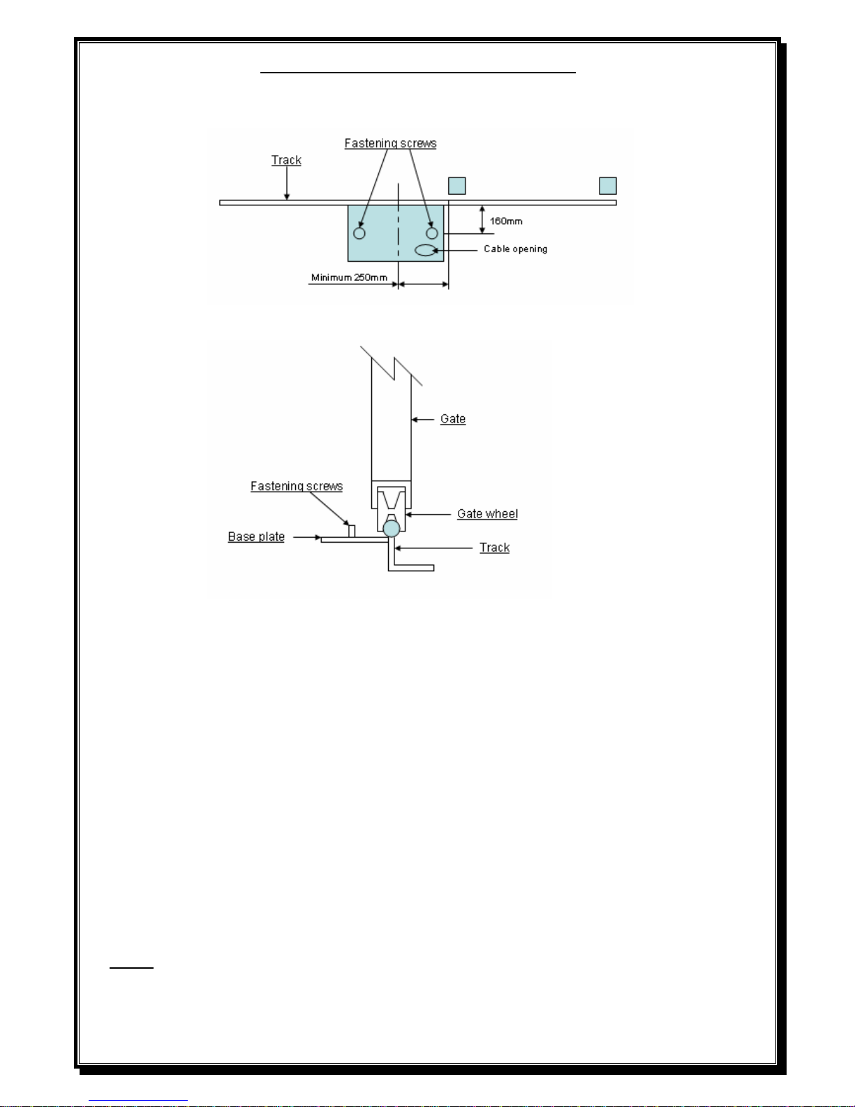
BASE PLATE MOUNTING INSTRUCTIONS
1. Assemble base plate by fastening M10x30 Hex set screws into base plate from under
the base plate up and tightening into position.
2. Mount base plate with bolts 160mm from the centre of the gate track and centre of base plate a
minimum of 250mm away from the gate opening.
3. Secure the base plate to the gate track by welding the base plate directly to the gate track. (Ensuring a
distance of 160mm from centre of gate track to centre of fastening screws).
4. Fit all required cabling through hole provided in base plate.
5. Support the back of the base plate with 40x40x3 angle iron (not provided) or similar off cut steel
knocked approximately 300 to 400mm into the ground.
6. Fill area below and around the base plate with approximately 300x400x300 concrete to ensure that the
motor will be secure.
2
7.
NOTE - The DTS 412/624 motor must be fitted with a set of IR beams.
Page 3
Gearbox mounting instructions
1. Fit gearbox over mounting bolts protruding from base plate.
2. Slide gate fully open and closed, insuring pinion gear has approximately 5mm clearance to gate at all
times.
3. Fasten gearbox down firmly to base plate using M10 washers and nuts.
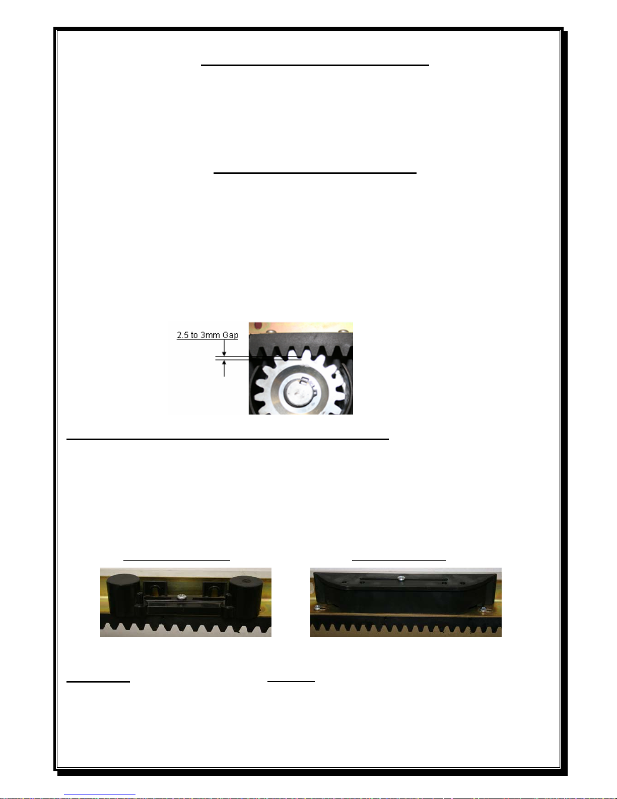
Rack mounting instructions
1. Unlock and pull manual override lever fully out to disengage gearbox.
2. Using a 2,5 to 3mm spacer between the pinion gear and the rack, mount the rack
using Tek screws No12x20 (not provided) and screw the rack to the gate starting
from the tail of the gate and ensuring that the rack is mounted level.
(A spacer can also be put between motor and base plate when fitting rack).
NB: Ensure that one of the screws attaching the nylon rack to the angle is in line with the
limit switch spring when the gate is fully closed.
Limit switch actuator mounting instructions
1. Remove screw attaching the nylon rack to angle that is closest to the position that
you wish the gate to stop.
2. Fit limit switch actuator with screw provided, screwing into the nylon rack.
3. Adjust limit switch actuator so that the gate stops approximately 10mm before
the post.
Magnetic limit actuator Spring limit actuator
Important: A solid stop must be fitted at both ends of the gate to prevent the gate from moving past its
full open or close position.
3
Page 4
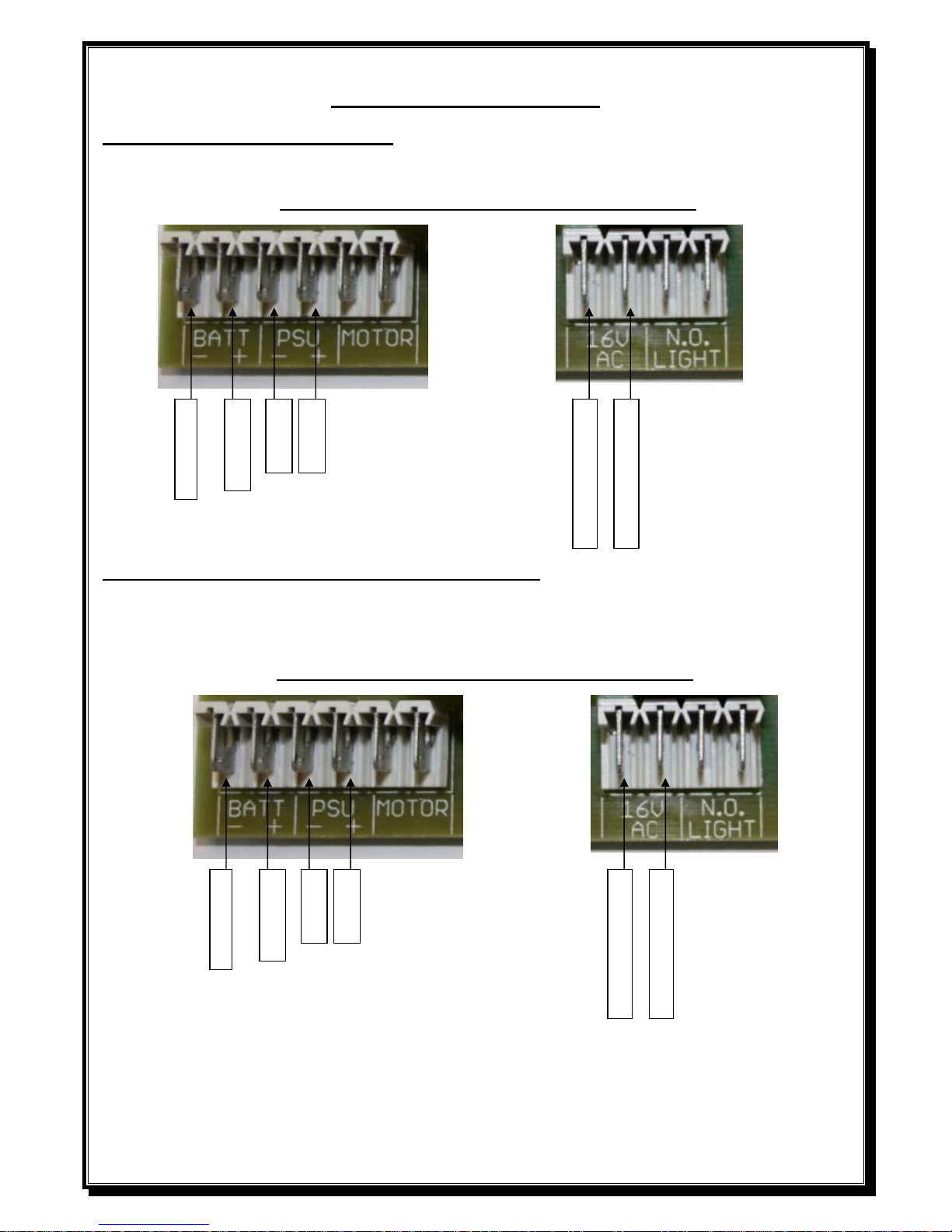
POWER CONNECTIONS
Low voltage Plug in transformer.
Connect 16V AC connectors on plug in transformer to 16V AC connectors on controller card.
DO NOT CONNECT 220V DIRECTLY TO PCB
Low voltage on board transformer – 220V at gate.
Connect 220V AC to input side of 16V AC transformer (black & brown wires), connect output
wires (red) to16V AC connectors on controller card.
DO NOT CONNECT 220V DIRECTLY TO PCB
IF 220V IS USED AT GATE MOTOR, A SEPARATE DOUBLE POLE ISOLATOR MUST
BE FITTED WITHIN 1M FROM MOTOR.
BAT
(
-
)
BLACK
BAT (+) RED
NOT USED
NOT USED
16 VAC from transformer
16 VAC from transformer
BAT
(
-
)
BLACK
BAT (+) RED
NOT USED
NOT USED
16 VAC from transformer
4
16 VAC from transformer
Page 5
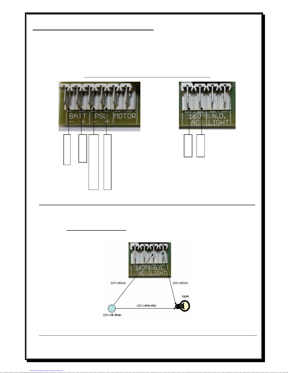
High access power supply unit – 220V at gate.
r on side of power supply unit.
DO NOT CONNECT 220V DIRECTLY TO PCB
Connect 220V AC to LEN (Live/Earth/Neutral) connecto
Black lead from power supply unit gets connected to – ( neg.) PSU connection on Pcb.
Red lead from power supply unit gets connected to + ( pos.) PSU connection on Pcb.
NOT USE POWER SUPPLY (PSU) UNIT AND LOW VOLTAGE TRANSFORMER (16V AC) TOGETHER.
DO
COUR
IF 220V IS USED AT GATE MOTOR, A SEPARATE DOUBLE POLE ISOLATOR MUST
BE FITTED WITHIN 1M FROM MOTOR.
TESY LIGHT OUTPUT (Will stay on for 3 minutes after a trigger is received)
DO NOT CONNECT 220V DIRECTLY TO PCB UNDER ANY CIRCUMSTANCES.
BAT
(
-
)
BLACK
BAT (+) RED
NOT USED
NOT USED
(-) DC
(+) DC
Voltage from transformer
5
Voltage from transformer
Page 6

DO ALL RUNTIME AND TRANSMITTER PROGRAMMING BEFORE CONNECTING AN Y AD DITIONAL
INPUTS SUCH AS, –INTERCOM, BEAMS ETC.
NOTE- IR beams must be fitted if DTS 412/624 motor is installed.
DO NOT CONNECT 220V DIRECTLY TO PCB
Dipswitch selections to activate a function.
ing or if neither limit
switches are activated).
ange
Dipswitch 1 - Programming.
2 - Motor direction. (This can only be changed before programm
3 – Auto close.
4 – Condominium mode.
5 – P.I.R.A.C. mode
6 – Slow down distance ch
Dipswitch selection for programming. (With dipswitch 1 ON)
Dipswitch 3 – Auto close. (Infra red beams must be fitted if auto close is activated).
Dipswitch 4 – Pedestrian (Distance and time).
6
Page 7

PROGRAMING
1 – Run Time Setup (This will automatically happen when triggered after total power up or
by following the steps below).
• Gate approximately 1metre open
ith all dipswitches OFF (excluding dipswitch 2 pending motor direction), press & release
Bt/SET button.
l automatically run at fast speed.
• end of run time setup.
• W
• Gate will close, open and close again and stop on close limit (Motor speed can be increased
lding down the Bt/SET button). The during programming of open cycle by pushing and ho
closing cycle of programming wil
Control card will beep to confirm
NOTE: If gate opens first, dipswitch number 2 is wrongly selected.
2 – Auto close
(Default 15 seconds) (Infra red beams must be fitted if auto close is activated).
• Switch Dipswitch 1 and 3 on.
• Press & hold Bt/SET button
• PCB will Beep (1 Beep = 1 Sec)
• Release Bt/SET button at required auto close time.
• Switch Dipswitch 1 and 3 off.
• activate the auto close.
Switch Dipswitch 3 back on to
3 – Pedestrian Opening
(Default 1 meter / 4 seconds auto close)
n.
Gate will open.
pening distance.
• auto close time required.
• ired pedestrian auto close time.
•
To reset factory default push Bt Lrn or Pd Lr ately 5
seconds, the PCB will give 2 short b
• Switch Dipswitch 1 and 4 on.
• Gate should be in closed positio
• Press & Release Bt/SET Button.
•
• Press & release Bt/SET button to stop gate at required pedestrian o
Press & Hold Bt/SET button to program
• Control card will Beep (1 Beep = 1 Sec)
Release Bt/SET button at requ
• Gate will close again.
Switch Dipswitch 1 and 4 off.
n, then press and hold Bt/SET for approxim
eeps as acknowledgement.
7
Page 8

Load setting
To adjust the load, turn the provided load pot very slowly to determine the load setting (Minimum-
nticlockwise & Maximum clockwise). The control card will beep as you turn the pot (1 - 5 beeps).
a
ON BOARD RECEIVER PROGRAMING
The onboard receiver is designed to work with Sentry rolling code transmitters.
The button used r used for L
PROGRAMMING A
TRANSMITTER FOR FULL
OPEN OPERATION –Bt Lrn
PROGRAMMING A
TRANSMITTER FOR PEDESTRIAN
OPERATION-Pd Lrn
1.
fo Bt Lrn CANNOT be Pd rn and vice versa.
should bTo erase a button from ct pro e for Bt Lrn
and not Pd Lrn.
Simply push and hold th e Pd Lrn for 5 seconds, the en push the button you want to
erase, the board will give 2 beeps as confirmation. That button is then erased and can be learned into the correct input.
rase:
the receiver, in case of incorre
e Bt Lrn or th
gramming i.e. blue button
board will give 1 beep. Th
To master e
eeps. Keep holding for Push and hold the Bt Lrn or the Pd Lrn button, after 5 seconds the board with give 1 b
another 5 seconds then the board will give 2 beeps. All transmitters will now be erased.
8
Push the Bt Lrn button, the
RX led will go on.
d button on
. Repeat Step 1 and 2 for
be
programmed for this
1. Push the Pd Lrn button, the
RX led will go on.
d button on
.
. Repeat Step 1 and 2 for
e
programmed for this
2. Push the require
the transmitter, the board
will give 2 beeps.
3
additional transmitters. Up to
25 transmitters can
operation.
2. Push the require
the transmitter, the board
will give 2 beeps
3
additional transmitters. Up to
5 transmitters can b
operation.
Page 9

ELECTRONICS
FEATURES:
1. Standard
2. Easy motor direction chang
3. Auto close facility (Infra re uto close is activated).
Condominium / Free exit loop facility
d Access Control) facility
(Ramp down) facility
e
d beams must be fitted if a
4.
5. P.I.R.A.C (Passive Infra Re
6. Slowdown
1. Standard Mode (No function selected)
When the gate is activated it will open and can be stopped in mid cycle by pressing the
itter or push button can reverse the
ain on its open limit until it is triggered to close.
If main power fails, the motor will still operate until battery reaches 20 volt. Gate will then
ng the motor by the override lever. When the
2. Easy motor direction change (Dipsw
transmitter or manual push button. Pressing the transm
gate. In standard mode the gate will rem
remain close. Change to manual by overridi
main power comes on again, lock in the override lever and the motor will function as
normal.
itch 2)
dipswitch, the motor direction and the limit wires By selecting the
are changed
utomatically a
. Dipswitch ON, gate closes to the right. Dipswitch OFF, gate closes to the
Auto close (Dipswitch 3
left.
3. On) (Infra red beams must be fitted if auto close is activated).
open limit, the gate will wait the
If the gate is triggered while the gate is
is in its opening cycle, the
gate will close after the preprogrammed auto close time (from any position, not only from
the open limit)
When Auto close is activated and the Gate opens to the
pre-programmed time before automatically closing.
in its closing cycle it will stop and reopen.
To override the auto close wait till the gate reaches its open limit then press & hold the
transmitter or manual push button for 5 sec. (The control card will give 1 long beep to
9
confirm the override) To reactivate the auto close, press the transmitter or manual push
button.
If the transmitter or manual push button is pressed while the gate
Page 10

4. Condominium/free exit loop (Dipswitch 4 On)
When condominium/free exit loop is activated on the unit, the unit will not respond to an
transmity ter or manual push button while in its opening cycle or open position. When the
closing cycle and the transmitter or manual push button is pressed the gate
will stop and open. Auto close cannot be over ridden in condominium mode. If main power
en remain open.
5.
gate is on the open limit the unit will automatically wait the pre-programmed auto close
time and then close (even if auto close function is not selected i.e. dipswitch 3 is off).When
the gate is in its
fails, the motor will still operate until battery reaches 20 volt. Gate will th
Change to manual by overriding the motor by the override lever. When the main power
comes on again, lock in the override lever and the motor will function as normal.
P.I.R.A.C (Passive Infra Red Access Control) (Dipswitch 5 On)
With P.I.R.A.C mode activated, if the gate is in its opening cycle and the IR beam is
activated and released the gate will stop and close immediately. When the gate is on the
open limit the unit will not automatically close unless auto close has been selected.
6. Slowdown (Dipswitch 6)
With dipswitch selected ON, the gate will have a long close and open ramp down distance,
NO ded).
and with the dipswitch OFF, a short ramp down distance.
TE - (For any gate exceeding 3 meters width, the long ramp down is recommen
10
Page 11

PCB Control card.
For PCB identification
2 x Voltage regulators = 24V motor.
1 x Voltage regulator = 12V motor.
NB
– When connecting intercoms to the control card, please ensure that your intercom trigger output is
potential free (ZERO voltage). If not, a gate relay module must be fitted.
11
Page 12

TROUBLESHOOTING
SYMPTOMS CAUSES ACTION
When pressing the remote
transmitter the gate operator
will not respond at all
Or
PCB responds but gate will
not open
Transmitter battery flat.
Transmitter physically
damaged.
Transmitter has not been
programmed into the receiver
memory.
Condominium /loop option is
not activated and the battery
has reached its low level
(10/20 Volt) Indicated by 3
beeps / 3 beeps.
Replace transmitter battery.
Check with supplier.
Follow the receiver setup
instructions.
Check the household main
supply, the transformer or PSU
and all related cabling.
When pressing either the
transmitter or the PCB
button or the hardwire
button on the wall, the gate
opens +- half a metre and
stops.
The transmitter is being
pressed and held.
The button input is being
pressed and held.
Press and release the
transmitter button to operate
the gate.
Press and release the button to
operate the gate.
Replace the button or rewire
the equipment.
Replace the switch, rewire
The button is jamming in the
N/C position or has been wired
normally closed.
The opposite limit switch is
jamming N/C or has been
wired up N/C.
12
correctly or check limit spring
assembly.
Page 13

13
Before operating, the unit
gives two long beeps
The primary supply has
failed and the unit is running
on battery reserve.
Check the household main
supply, the transformer or
PSU and all related cabling.
The gate opens but will not
close
The primary supply has failed
and the unit is running on
battery reserve with the
condominium/loop option
selected and it has reached its
low battery limit (10/20 Volt)
indicated by 3 beeps / 3 beeps.
Safety infra-red beams are
obstructed or the beams
equipment/cabling are faulty.
Check the household main
supply, the transformer or
PSU and all related cabling.
Clear obstruction or
repair/replace safety infra-red
beams equipment/cable.
The gate when closing stops
and reverses or when
opening stops.
OR
Gate tries to run and the
relays kick out.
The unit is sensing an
obstruction
The infra-red beam has been
triggered.
Another trigger has been
received by the control card.
Encoder is faulty.
Clear obstruction or adjust
load sensing.
Clear obstruction.
Check with other operators on
the system.
Turn ring magnet on the motor
by hand: if no activity on the
encoder LED, contact
supplier.
Gate does not remain open.
Auto close has been selected.
Another user has triggered the
unit.
Condominium/loop has been
selected.
Deselect auto close or use auto
close override.
Deselect condominium / loop
mode.
When the beams input is
triggered, the gate stops and
reverses during opening
cycles.
P.I.R.A.C. mode has been
selected.
Gate is closing in the wrong
direction.
Deselect P.I.R.A.C. mode
Dipswitch 2 is selected
incorrectly.
Page 14

14
The unit beeps 3 times and
opens partially, beeps 3
times and the closes. This
can sometimes continue
indefinitely.
The pedestrian (Pd) mode is
being triggered. This is
constant if the sequence
keeps repeating.
A transmitter code has been
programmed into the
pedestrian (Pd Lrn) function
of the receiver.
Receiver is faulty and
transmitting constantly
Check with the other
operators and check
switching equipment /
cabling attached to the (Pd)
input.
Re-code the receiver as per
instructions
Check with supplier.
When gate reaches a limit
actuator, the unit does not
stop running.
Limit inputs wired incorrectly
(out of sync’ with the motor
direction.)
Limit switch is faulty.
Re-wire
Check with supplier.
Gate motor is jumping teeth
on the rack.
Pinion to rack spacing is
incorrect.
Rack is insufficiently fastened
to gate leaf.
Re-align.
Re-align and correct fastening.
Gate jams in the open or
closed position and is not
easy to manually release.
Gate is running too far.
Gate is running past its limit
actuator.
Adjust the limit actuators so
that the gate does not ram into
the end stops.
Replace the switch, rewire
correctly or check limit spring
assembly.
Page 15

15
Manufacturers warranty
.
• A d b y a 1 rranty
fr
• All goods are warranted to be free from faulty components and manufacture.
• Faulty goods will be repair l urity
Products, free of charge.
• This warranty is subject to e to the premises of DTS
Security Products.
• This warranty excludes lig sect d ge caused
by faulty installation.
• In the event of the goods being supplie
appointed installer of DTS Security Products, the claim must be directed to
that supplier.
• The carriage of goods is fo ccount
• This w lation and application of goods,
as laid out in the applicable documentation accompanying said goods, is
adhered to.
• All warranty claims must be acco nvoice.
• T cur or thei d as
h urit Products and / or their
liable for consequential or incident damages howsoever arising.
y DTS Security carrll goods manufacture
om date of invoice.
2 month factory wa
ed or replaced at the so
the goods being return
e discretion of DTS Sec
d
htening damage, in amage and dama
d by dealer, merchant, agent or duly
r the customer’s a .
arranty is only valid if the correct instal
mpanied by the original i
he liability of DTS Se
erein set out DTS Sec
ity Products and / r distributors is limite
distributors will not bey
 Loading...