

Page 1
DMX STROBE 1500
User’s Manual Rel 1.1
D.T.S. Illuminazione srl - ITALY
http://www.dts-lighting.it
GB
Made in Italy
Page 2

2
Le informazioni contenute in questo documento sono state attentamente redatte e controllate. Tuttavia
non è assunta alcuna responsabilità per eventuali inesattezze. Tutti i diritti sono riservati e questo
documento non può essere copiato, fotocopiato, riprodotto per intero o in parte senza previo consenso
scritto della D.T.S .
DTS si riserva il diritto di apportare senza preavviso cambiamenti e modifiche estetiche , funzionali o di
design a ciascun proprio prodotto. D.T.S non assume alcuna responsabilità sull’uso o sull’applicazione dei
prodotti o dei circuiti descritti.
The information contained in this publication has been carefully prepared and checked. However, no
responsibility will be taken for any errors. All rights are reserved and this document cannot be copied,
photocopied or reproduced, in part or completely, without prior written consent from D.T.S.
D.T.S. reserves the right to make any aesthetic, functional or design modifications to any of its products
without prior notice. D.T.S. assumes no responsibility for the use or application of the products or circuits
described herein.
DMX STROBE
Les informations contenues dans le présent manuel ont été rédigées et contrôlées avec le plus grand
soin. Nous déclinons toutefois toute responsabilité en cas d'éventuelles inexactitudes. Tous droits
réservés. Ce document ne peut être copié, photocopié ou reproduit, dans sa totalité ou partiellement,
sans le consentement préalable de .
D.T.S.
de design, sans préavis, à chacun de ses produits. décline toute responsabilité sur l'utilisation ou
Todos los derechos han sido reservados y este documento no puede ser copiado, fotocopiado
D.T.S.
estético, funcional o de diseño a cada producto suyo. no se asume responsabilidad de
se réserve le droit d'apporter toutes modifications et améliorations esthétiques, fonctionnelles ou
D.T.S.
sur l'application des produits ou des circuits décrits.
Las informaciones contenidas en este documento han sido cuidadosamenteredactadas y
controladas. Con todo, no se asume ninguna responsabilidad por eventuales inexactitudes.
o reproducido, total o parcialmente, sin previa autorizaciónescrita de
se reserva el derecho a aportar sin previo aviso cambios y modificaciones de carácter
D.T.S.
ningún tipo sobre la utilización o sobre la aplicació
n de los productos o de los circuitos descritos.
D.T.S
D.T.S.
Page 3
STROBO DMX
3
DMX STROBE
INDEX:
1- TECHNICAL FEATURES 4
2- IMPORTANT SAFETY INFORMATION 5
2.1 Fire prevention
2.2 Prevention of electric shock
2.3 Protection against ultraviolet radiation
2.4 Safety
2.5 Level of protection against the penetration of solid and liquid matter
3- VOLTAGE AND FREQUENCY 6
4- INSTALLATION 6
4.1 Safety cable
4.2 Protection against liquids
4.3 Risk of fire
4.4 Forced ventilation
4.5 Ambient temperature
5- MAINS CONNECTION 7
5.1 Protection
6- DMX SIGNAL CONNECTION 7
6.1 DMX Addresses
6.2 Selecting the DMX address
7- DISPLAY FUNCTIONS 9
8- ERROR MESSAGES 10
9- PERIODIC CLEANING 11
9.1 Front Glass
9.2 Fans and air passages
10- PERIODIC CONTROLS 11
11- DMX PROTOCOLS 12
Page 4
4
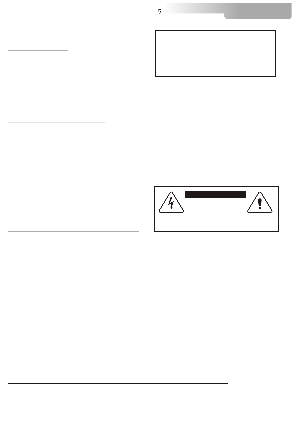
1- TECHNICAL FEATURES
The DMX STROBE 1500 is fitted with a xenon XOP 15 linear lamp
(XOP 15 lampholder base)
The unit incorporates:
USITT Standard DMX 512 input
2 or 4 DMX channels
4 -eight digit- LED display with 4 buttons
2 XLR connectors (In and Out) with 3 and 5 pins selectable by user
Power supply:
230 V (50/60 Hz)
Power consumption: 1500 W.
Operating ambient temperature 0° / 40°
Weight
4 Kg
DMX STROBE
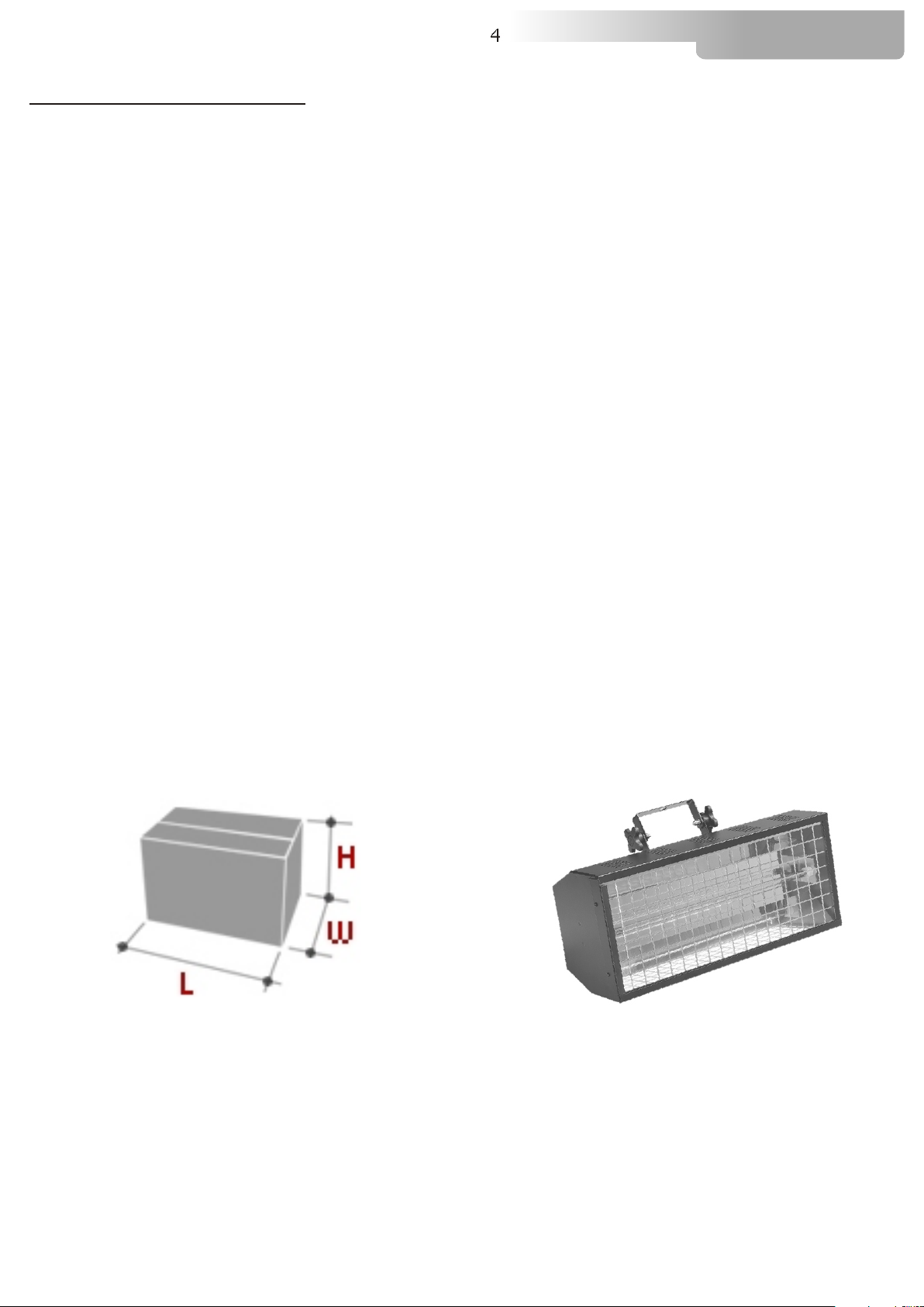
Packing Dimensions (HxWxL)
260 x 230 x 470 mm
Weight 5 Kg
Dimensions (HxWxL)
Projector (180x180x410)
Weight 4 Kg
Page 5
5
DMX STROBE
2- IMPORTANT SAFETY INFORMATION
2.1 Fire prevention:
-Never locate the fixture on any flammable surface.
ATTENTION:
1)OPERATE THIS UNITS ONLY WITH PROPER AC VOLTAGE
2)READ INSTRUCTION MANUAL CAREFULLY BEFORE OPERATION
3)TO AVOID THE RISK OF ELECTRIC SHOCK AND FIRE, DO NOT EXPOSE
THIS UNIT TO MOISTURE OR HIGH HUMIDITY
4)NO USER SERVICEABLE PARTS INSIDE
SERVICE PERSONNEL:
1)SEE SERVICE MANUAL BEFORE OPENING
2)DISCONNECT PLUG BEFORE OPENING
3)ALL PARTS MUST BE REPLACED BY ORIGINAL SPARE PARTS
-Minimum distance from flammable materials: 1 MT.
-Minimum distance from the closest illuminable surface: 2 MT.
-Replace any blown or damaged fuses only with fuses of identical value. Refer to the wiring diagram if
there is any doubt.
-Connect the unit to mains power via a thermal magnetic circuit breaker.
2.2 Prevention of electric shock:
-High voltage is present inside the unit. Unplug the unit prior to performing any function which involves
touching the inside of the moving head, including lamp replacement.
-The level of technology present in the DMX STROBE requires the assistance of specialised personnel for
all servicing. Please refer to an authorised DTS service centre.
-A good earth connection is essential for proper functioning of the projector.
-Never connect the unit without proper earth connection.
-The fixture should be located in places with a good air ventilation.
CAUTION
RISK OF ELECTRIC SHOCK
DO NOT OPEN
WARNING: SHOCK HAZARD-DO NOT OPEN
ACHTUNG: GEFAHRLICHE NETZSPANNUNG IM INNENTEIL-NICHT OFFNEN
AVIS: RISQUE DE CHOC ELECTRIQUE-NE PAS OUVRIR
2.3 Protection against ultraviolet radiation:
-Never turn on the lamp if front glass, or metal cover is damaged. Their respective shielding functions
will only operate efficiently if they are in perfect working order.
-Never look directly the lamp when it is on.
2.4 Safety:
-The projector should always be installed with bolts, clamps and other tools that are capable of
supporting the weight of the unit.
-Always use a second safety cable to sustain the weight of the unit in case of the failure of the main
fixing point.
-The external surface of the unit, at various points, may exceed 70°C. Never handle the unit until at
least 10 minutes have elapsed since the lamp was turned off.
-Always replace the lamp if any physical damage is evident.
-Never install the fixture in an enclosed area lacking sufficient air flow. The ambient temperature should
not exceed 40°C.
-A hot lamp may explode, so always wait for at least 10 minutes prior to attempting to replace the lamp.
-Always wear suitable hand protection when handling the lamp.
2.5 Level of protection against the penetration of solid and liquid matter:
-The projector is classified as an ordinary appliance and its protection level against the penetration of
solid and liquid matter is IP 20.
Page 6

6
DMX STROBE
3- VOLTAGE AND FREQUENCY
The DMX STROBE operate at 230 VOLT 50 or 60 Hz.
4- INSTALLATION
DMX STROBE should be ceiling mounted.
For ceiling mounted installations, we reccomend the use of appropriate clamps to fix the unit to the
mounting surface.
The supporting structure from which the unit is hung should be capable of bearing the weight of the
unit, as should any clamps used to hung it.
4.1- Safety cable
We recommend the use of a safety cable or chain connected to the DMX STROBE and to the suspension
truss in order to avoid the fixture accidentally falling should the main fixing point fail. Make sure that the
iron cable or chain can bear the weight of the entire unit.
4.2- Protection against liquids
The projector contains electric and electronic components which should under no circumstances come
into contact with oil, water or any other liquid. The proper unit functioning would be compromised
should this occur.
4.3- Risk of fire
Each fixture produces heat and must be installed in a well-ventilated place. The minimum recommended
distance from flammable material is 1 MT.
Minimum distance from the object being illuminated is 2 MT.
4.4- Forced ventilation
You will note, on inspection, that the unit features various air inlets and cooling fan. These should, under
no circumstances, be blocked or obstructed whilst the projector is in operation.
Doing so could cause the fixture to seriously overheat thereby compromising its proper operation.
4.5- Ambient temperature
The projector should never be installed in places that lack a constant air flow. The ambient temperature
should NOT exceed 40°C.
Page 7

7
DMX STROBE
5- MAINS CONNECTION
230 Volt 50/60 Hz
DMX STROBE operate at 230 VOLT 50-60 Hz.
Prior to connecting the unit to your mains supply,
ensure that the model in your possession correctly matches
the mains supply available. For connection purposes,
ensure that your plug is capable of supporting 16 amps at 230V,
Strict adherence to regulatory norms is strongly recommended.
FUSE 16 A
5.1- Protection
The use of a thermal magnetic circuit breaker is recommended for each DMX STROBE.
A good earth connection is essential for the correct operation of the projector.
6- DMX SIGNAL CONNECTION
The unit operates using the digital DMX 512 (1990) signal. Connection between the mixer and the unit or
between units must be carried out using a two pair screened ø 0.5 mm cable and a CANNON XLR 5 or 3
pins connector.Ensure that the conductors do not touch each other.Do not connect the cable ground to
the XLR chassy
The plug housing must be isolated. Connect the mixer signal to the DMX IN projector plug and connect
it to the next projector by connecting the DMX OUT plug on the first projector to the DMX IN plug of the
second one.
In this way, all the projectors are cascade connected.
NB. If the display showing the DMX address flashes, then one of the following errors has occurred:
- DMX signal not present
- DMX address not valid
- DMX reception problem
CONTROLLER
S TA ND AR D
D M X 5 1 2
5
1
1=GND
2=DATA3=DATA+
4 2
3
For Installations where long distance DMX cable connections are needed,we suggest to use a Dmx
terminator.
The DMX terminator is a male XLR 3-5 pins connector with a 120 ohm resistor between pin 2 and 3.
The DMX terminator must be plugged into the last unit (DMX out panel connector) of the DMX line.
15
4
2
3
OUT
PLACE A 120 OHM RESISTOR BETWEEN PIN 2
AND 3 OF A MALE XRL CONNECTOR AND PLUG IT
INTO THE DMX OUT PANEL CONNECTOR OF THE
LAST UNIT CONNECTED TO THE DMX LINE
PIN 3
120 ohm
PIN 2
Page 8

8
DMX STROBE
6.1-DMX Addresses
Dmx STROBE 1500 can be used in two different modes: 2 or 4 DMX (default) channels.
If you want to use the DMX STROBE in 2 channels mode, select the 2 CH mode from the MODE menu
and set the following addresses on the mixer:
Projector 1 A001
Projector 2 A003 If you want to select the next projector, just add “2”
Projector 3 A005
….. A….
projector 6 A011
If you want to use the DMX STROBE in 4 channels mode, select the 4 CH mode from the MODE menu
and set the following addresses:
Projector 1 A001
Projector 2 A005 If you want to select the next projector, just add “4”
Projector 3 A009
….. A….
Projector 6 A021
6.2-Selecting the DMX address
1) Press the UP-DOWN key until you reach the required DMX channel. The numbers on the display will
start to flash (but the new DMX address hasn't yet been set).
2) Press ENTER to confirm your selection. The numbers on the display will stop flashing and the
projector is now setted to the new DMX address.
TRICKS:
if you keep pushed the UP or DOWN keys, the channels are calculated more quickly and you get a
faster selection.
Page 9

7- DISPLAY FUNCTIONS
9
DMX STROBE
DMX IN DMX OUT
DMX IN DMX OUT
DISPLAY
MICROPHONE
MAINS
230V 50 / 60Hz
FUSE
16 A
MENU
ENTER
UP
DOWN
DISPLAY FUNCTIONS
The DMX STROBE display panel shows all the available functions . Using these functions, it is
possible to change some of the parameters and add some functions. Changing the DTS setting
can vary the functions of the unit so that it does not respond to the DMX 512 used to control it.
Carefully follow the instructions below before carrying out any variations or selections.
NOTE: the symbol shows which key has to be pushed to obtain the desired function.
MENU
REVERSE DISPLAY
Reverses display's reading depending on
the mounting position
(On the ground or suspended).
Up-Down
DMX MODE
To select DMX mode : 2-4 channels
Up-Down
MENU
TEST MODE
Unit test.
Up-Down
MENU ENTER
AUTOMATIC MODE
Automatic game without DMX controller
ENTERUp-Down
position
Up-Down
Floor
ENTER
Suspension
Up-Down
Up-DownMENU ENTER
Up-Down
ENTER
position
2 CHANNELS
4 CHANNELS
Unit test with strobe at different frquencies
Up-DownENTER ENTER
Up-Down
Up-Down
ENTER
ENTER
ENTER
Intensity (0-255)
Strobe rate (0-255)
Up-DownENTER
ENTER
ENTER
Up-Down
MENU
DEFAULT
To restore default setting
Musical strobe function
ENTER ENTER
Up-Down
Page 10

7- DISPLAY FUNCTIONS
10
DMX STROBE
Up-Down
MENU
SOFTWARE
Software version
MENU ENTER
Up-Down
TIMER
lamp life TIME (reset possible)
and total UNIT LIFE TIME (reset not possible)
MENU ENTER
Up-Down
SENSIBILITY
Microphone Sensibility adjustment.
8- ERROR MESSAGES
ENTER
Software version for main pcb
Up-Down
Up-Down
Up-Down
Up-Down
ENTER
ENTER
ENTER
ENTER
Lamp life time
Unit life time
Lamp life reset
ENTER
ERROR: DMX ADDRESS
ERROR: AUTO MODE INPUT
Page 11

11
DMX STROBE
9- PERIODIC CLEANING
9.1- Front glass
Even a fine layer of dust can substantially reduce the luminous output . Regularly clean the front
glass using a soft cotton cloth, dampened with a specialist lens cleaning solution.
9.2- Fan and air passages
The fan and air passages must be cleaned approximately every 6 weeks. This periodic cleaning will
depend of course, on the conditions in which the projector is operating. Suitable instruments for
performing this type of maintenance are a brush and a common vacuum cleaner or an air
compressor. If necessary, clean the fans and air passages more frequently.
10- PERIODIC CONTROLS
Attention
Disconnect mains power prior to removing the projector housing.
Lamp
The lamp should be replaced if there is any visible damage or deformation due to heat. This will
help to avoid the danger of the lamp exploding.
Electrical components
Check all electrical components for correct earthing and proper connection of all connectors;
refasten them if necessary.
Fuse replacement
Locate the fuse, which protects the lamp and electronics, in the rear panel base of the DMX
STROBE.
Using a multimeter, test the condition of the fuse, replacing it with one of equivalent type if
necessary.
Page 12

11- DMX PROTOCOL
2 CHANNELS MODE (DEFAULT)
1 DIMMER
2 STROBE RATE
DMX CHANNEL 1
DMX range
Value
Mid point
DMX value
0-255
DMX CHANNEL
DMX range
Value
0-255
Mid point
DMX value
Parameter: DIMMER
Move
range
(degrees)
2
Parameter: STROBE RATE
Move
range
(degrees)
Strobe at different frquencies from min to max (1 to 25 flashes/sec)
12
DMX STROBE
Mode Option Function
Proportional dimmer
Mode Option Function
Page 13

11- DMX PROTOCOL
4 CHANNELS MODE
1 DIMMER
2 STROBE RATE
3 STROBE DURATION
4 FUNCTIONS
DMX CHANNEL 1
DMX range
Value
0-255
Mid point
DMX value
Parameter: DIMMER
Move
range
(degrees)
13
DMX STROBE
Mode Option Function
Proportional dimmer From min to max (0-100%)
DMX CHANNEL
DMX range
Value
0-255
DMX CHANNEL
DMX range
Value
0-7
8
-15
16
-23
24-31
32-39
40-47
-55
48
-63
56
64-71
-79
72
-87
80
-95
88
96
-103
104-111
112-119
120-127
128-135
136-143
144-151
2
Mid point
DMX value
3
Mid point
DMX value
Parameter: STROBE RATE
Move
range
(degrees)
Strobe at different frquencies from min to max (1 to 25 flashes/sec)
Parameter: STROBE DURATION
Mode Option Function
Move
(degrees)
range
Mode Option Function
20 ms flash duration time
40 ms flash duration time
60 ms flash duration time
80 ms flash duration time
100 ms flash duration time
120 ms flash duration time
120 ms flash duration time
140 ms flash duration time
160 ms flash duration time
180 ms flash duration time
200 ms flash duration time
220 ms flash duration time
240 ms flash duration time
260 ms flash duration time
280 ms flash duration time
300 ms flash duration time
320 ms flash duration time
340 ms flash duration time
360 ms flash duration time
Page 14

DMX CHANNEL
DMX range
Value
152-159
160-167
168-175
176-183
184-
191
192-199
200-207
208-215
216-223
224-231
232-
239
240-247
248-255
3
Parameter: STROBE DURATION
Mid point
DMX value
Move
range
(degrees)
Mode Option Function
14
DMX STROBE
380 ms flash duration time
400 ms flash duration time
420 ms flash duration time
440 ms flash duration time
460 ms flash duration time
480 ms flash duration time
500 ms flash duration time
520 ms flash duration time
540 ms flash duration time
560 ms flash duration time
580 ms flash duration time
600 ms flash duration time
620 ms flash duration time
DMX CHANNEL
DMX range
Value
0-59
60
-119
120
-179
-255
180
4
Mid point
DMX value
One Shot function (with Strobe rate passage from 0 to 255 = One Shot)
Parameter: FUNCTIONS
Move
range
(degrees)
Musical Strobe Rate (internal microphone acivated)
Mode Option Function
No function
Random Strobe Rate
Page 15

NOTES:
15
DMX STROBE
Page 16

The information contained in this publication has been carefully prepared and checked.
However, no responsibility will be taken for any errors. All rights are reserved and this document
cannot be copied, photocopied or reproduced, in part or completely, without prior written consent
from D.T.S.
D.T.S. reserves the right to make any aesthetic, functional or design modifications to any of its
products without prior notice. D.T.S. assumes no responsibility for the use or application of the
products or circuits described herein.
MADE IN ITALY
*0517I032*
0517I032
D.T.S. Illuminazione s.r.l - Via Fagnano Selve 10-12-14 47843 - Misano Adriatico (RN) Italy
Tel. +39 0541 611131 Fax +39 0541 611111 info@dts-lighting.it www.dts-lighting.it
 Loading...