

Page 1
Revision 2.2
Page 2

Table of Contents
1 Introduction
1.1 OVERVIEW...................................................................................................................1
1.2 REGULATORY NOTICES.............................................................................................2
1.2.1 Emi Notice .............................................................................................................2
1.2.2 Patents...................................................................................................................2
1.3 RETURNS.....................................................................................................................2
1.4 WARRANTY INFORMATION........................................................................................ 3
............................................................... 1
2 Unpacking ................................................................. 4
2.1 UNPACKING.................................................................................................................4
3 Encoder Box Controls and Connectors.................. 5
3.1 QUICK-START SET-UP................................................................................................5
3.2 ELECTRICAL SPECIFICATIONS..................................................................................5
3.3 FRONT PANEL CONTROLS AND INDICATORS .........................................................5
3.3.2 Surround Switch 0dB/-3dB...................................................................................6
3.3.3 TC Trig/TC bypass ................................................................................................ 6
3.3.4 Lfe On/Lfe Off........................................................................................................6
3.3.5 1509k/754k.............................................................................................................6
3.3.7 DVD Status Indicator ............................................................................................6
3.3.8 CD Status Indicator...............................................................................................7
3.3.9 TC Indicator Light ................................................................................................. 7
3.3.10 READY Light ......................................................................................................7
3.3.11 RESET Swit ch ( m oment ary)..............................................................................7
3.4 REAR PANEL CONNECTORS......................................................................................7
3.4.1 Mains Power with Power On/Off Switch .............................................................7
3.4.2 Time code Input .................................................................................................... 8
3.4.3 Bitstream Output................................................................................................... 8
3.4.4 L/R Digital Audio Input .........................................................................................8
3.4.5 LS/RS Digital Audio Input.....................................................................................8
3.4.6 Center/SubWoofer Digital Audio Input................................................................ 8
3.4.7 Input Channel Mapping ........................................................................................8
4 Example: Production Setups.................................. 9
4.1 GENERIC SETUP......................................................................................................... 9
4.2 AUTHORING SYSTEMS SUPPORT...........................................................................12
Revision 2.2 Page i
Page 3

5 DTS Record Panel Software.................................. 13
5.1 OVERVIEW.................................................................................................................13
5.1.1 Panel.................................................................................................................... 13
5.1.2 Using Panel in CD Code (44.1)........................................................................... 14
5.1.2 Optional Dos Utilities..........................................................................................14
6 E175-01 DVD Timecode Controller........................ 16
6.1 E175-01 DVD FEATURES .......................................................................................... 16
6.1.1 Interface I/O......................................................................................................... 16
6.1.2 Power...................................................................................................................16
6.2.2 Signal...................................................................................................................16
6.2 SETUP & INITIALIZATION.......................................................................................... 17
6.3 FUNCTIONAL DESCRIPTION .................................................................................... 17
7 CAD-4 Professional Decoder................................. 19
7.0 SET-UP.......................................................................................................................19
7.1 MAINS POWER ..........................................................................................................19
7.2 INTERFACE................................................................................................................19
7.2.1 Inputs...................................................................................................................19
7.2.2 Digital Outputs.................................................................................................... 19
7.3.3 Analog Outputs................................................................................................... 19
7.3 STATUS INDICATORS ............................................................................................... 19
Appendix A.................................................................... 20
Time code embedding specifications.............................................................................. 20
A1.0 DTS Bitstream Time code Embedding Specification..........................................20
Coding of preamble ........................................................................................................ 21
Table 1 Preamble Words................................................................................................ 21
32-bit mode ....................................................................................................................21
16-bit mode ....................................................................................................................21
burst_info........................................................................................................................ 21
Table 2 burst_info........................................................................................................... 21
data_type........................................................................................................................ 22
Table 3 Values of data_type........................................................................................... 22
Reserved bits.................................................................................................................. 22
error_flag........................................................................................................................ 22
data_type_dependent.....................................................................................................22
data_stream_number .....................................................................................................22
length_code.................................................................................................................... 22
Burst spacing..................................................................................................................23
Revision 2.2 Page ii
Page 4

The null data_type.......................................................................................................... 23
The DTS data_type ........................................................................................................23
Table 4 Values of data_type_dependent When data_type = 1 .......................................23
Placement of DTS frames into data bursts ..................................................................... 23
1.4.2 The time stamp data_type.................................................................................. 24
Figure 1. Encoding audio with time code. ....................................................................... 24
1.4.3 Preamble values.................................................................................................. 24
Time stamp payload ....................................................................................................... 24
Figure 2. Time stamps and DT S frames in the IEC958 data stream............................... 26
Table 6 Frame Rate Code .............................................................................................. 26
Appendix B.................................................................... 27
Compacting files using the Join program ..............................................................................27
DTS Encoding System User Information.................... 27
Revision 2.2 Page iii
Page 5

1 Introduction
1.1 OVERVIEW
This manual describes the configuration and operation of the DTS Professional Audio
Equipment, which includes the CAE-4 Professional Encoder, the CAD-4 Decoder, and the
E175-01 DVD Timecode Controller. This is the r eference equipment t o create DTS bitstreams
from 5.1 source mate r ial for DVD-Video and CD.
The manual explains the general requirem ents f or encoding. It also outlines specif ic product ion
scenarios. The scenarios serve as examples for conf iguring production environments.
Operating software is included in this pack age (on CD-ROM), and it runs on Windows 95, 98,
2000 or NT systems. Use of the DTS Record Panel is described in Section 5 of the manual. At
the end of each project, always comply with standard industry practice f or Qualit y Control (QC) .
It is strongly recommended that QC always include critical listening of encoded material to
verify acceptability of content for end users.
A software playback panel will be available in the upcoming months. Until then it may be
necessary to use a third party program (ie; Sound Forge) for play back of DTS files directly
from your computer. A t ypical application is illust rated in Figure 6.
The E175-01 DVD Timecode Controller is described in Sect ion 6 of this manual. It is used to
sync picture content with audio content for DVD-Video applications, enabling users to select an
encoding project start and end time.
Minimum Computer Requirements to oper at e the DTS Record Panel software:
1. Windows 95, 98, 2000 or NT
2. A PC with a minimum of 64 Mbytes of memor y, a separate system drive and a data drive
with 4Gbytes (content dependent) free on hard dr ive.
3. Your will need to turn off background prog rams running (ie; screen savers, virus scan – off ,
etc). This will insure a successful DTS encode bitstream capture into the computer.
4. It is suggested that in AGP video card be used where possible.
Sound Cards tested and verified for use with DTS Pro Audio Equipment:
1. SEK'D-PRODIF 96 Pro
2. Lynx One
3. Zefiro ZA2
4. MOTV 308/PC1324
Revision 2.2 Page 1
Page 6

1.2 REGULATORY NOTICES
1.2.1 Emi Notice
This equipment has been tested and f ound to com ply with the limits f or a Class A digit al device,
pursuant to Part 15 of the FCC Rules. These limits are designed to provide reasonable
protection against harmful interference when the equipment is operated in a commercial
environment. This equipment generates, uses, and can radiate radio f requency energy and, if
not installed and used in accordance with the instruction manual, may cause harmful
interference to radio comm unications. Oper ation of this equipment in a residential ar ea is lik ely
to cause harmful interf erence in which case the user will be required t o correct the interf erence
at his own expense.
Canadian Department of Communications compliance st at em ent:
This equipment does not exceed Class A limits per radio noise emissions for digital apparatus
set in the Radio Interference Regulation of the Canadian Department of Communications.
Operation in a residential area may cause unacceptable interf erence to r adio and TV r eception,
requiring the owner or operator to take whatever steps are necessary to correct the
interference.
Avis de conformite aux normes du ministere des Communications du Canada:
Cet equipment ne depasse pas les limites de Classe A D'emission de bruits radioelectriques
pour les appareils numeriques telles que perscrites par le Reglement sur le brouillage
radioelectrique etabli par le minister e des Communications du Canada. L'exploitation faite en
milieu residentiel peut entrainer le brouillag e des receptions radio et t elevision, ce qui olbigerait
le proprietaire ou l'operateur a prendre les dispositions necessaires pour en eliminer les
causes.
1.2.2 Patents
The DTS system has been granted the following patents:
US Pat. Nos. 5,451,942, 5,956,674, 5,974,380, 5,978, 762 and other worldwide patents issued
and pending. "DTS" and "DTS Digital Surround" ar e registered trademarks of Dig ital Theater
Systems, Inc., Copyright 2000 Digit al Theater Systems, Inc. All rights reserved.
1.3 RETURNS
If any of the items on your packing list cannot be found, contact DTS with the P/N and
description of the missing item(s). Refer to inf ormation below before sending any product back
to DTS.
For warranty repair, exchange or getting replacement par ts, please call your local DT S of fice or
dealer.
A DTS Return Authorization (“RA”) number is required before sending any item back to the
factory. At the time of the call, DTS will require that you provide the serial number of any unit(s)
for return before warranty replacement units will be sent. All return packag ing should be clearly
marked with the Return Authorization number on the outside of the package.
Revision 2.2 Page 2
Page 7

Please send all returns to:
North America Europe
Digital Theater Systems, Inc. DTS SA
5171 Clareton Drive Unit 5, Ruscombe Lane
Agoura Hills, California 91301-4523 USA Tavistock Industrial Estat e
Telephone: (818) 706-3525 Twyford, Berkshire RG10-9NJ
or toll free in USA: 800-959- 4109 UK
Customer Service Fax: (818) 879-2746 Telephone: 44-1189-349199
Fax: 44-1189-349198
1.4 WARRANTY INFORMATION
Equipment manufactured by DTS, Inc. is warranted against defects in materials and
workmanship for one year from date of purchase. There are no other expressed or implied
warranties.
DTS, Inc. obligation is restricted to repair and/or replacement of defective parts. Under no
circumstances will DTS, Inc. be liable for any other damage, either direct or consequential.
All requests for repairs or information should include the unit serial number to ensure rapid
service.
DTS OFFICES AND TECHNICAL SUPPORT
North America (corporate headquarters)
Telephone: (818) 706-3525
Fax: (818) 706-1868
DTS engineers are available to assist you. If you have an emergency after
business hours, please leave a message on the answering service and we will
return your call as soon as possible.
Europe (UK)
Telephone: 44-1189-349199
Fax: 44-1189-349198
INTERNET users may email DTS at the following address: dkrasnow@dtsonline.com
DTS Web Site: www.dtsonline.com
Future updates/new releases of the DTS Recor d Panel will be provided via the website.
Revision 2.2 Page 3
Page 8

2 Unpacking
2.1 UNPACKING
The packaging is designed for t ypical shipping and handling. Upon receipt of shipm ent, check
for signs of damag e before opening and report all damag e to the carrier. All shipments made
from DTS are the customer's responsibility once they leave our premises.
Before installation it is sugg ested that a complete inventory be taken t o minimize problems or
questions during installation. Addit ionally, save all packing mat erial until installat ion is com plete
in the unlikely event that a component(s) req uires return to the factory. Use the packing slip
that came with your unit to verify received inventory.
The following is a sample packing l ist for a single system.
Typical DTS Pro Audio Equipment Package consists of :
• CAE-4 Professional Encoder
• CAD-4 Decoder
• E175-DVD Timecode Controller
• E175-DVD (1/4” Jack) to Encoder ( XLR) Cable assembly
• E175-DVD power adapter
• DTS Software suite including the DTS Recor d Panal and bit str eam tools sof t ware on
CD-ROM
• Record Panel software on CD-ROM
• CAE-4 Encoder System Manual
• Spec Sheets for the CAE-4 Encoder and CAD-4 Decoder
Revision 2.2 Page 4
Page 9
3 Encoder Box Controls and Connectors
3.1 QUICK-START SET-UP
The diagram below illustrates a quick verification procedure for DTS equipment functionality
with minimal interface. If any system interface pr oblems are encountered, refer to this simple
set-up.
Time code Input #1 (From DA88)
ABC
CAD-4 Decoder
XLR Balance
Digital input*
*set selector switch out
Monitor
(analog out)
E175-01
DVD
+ 9V input
CAE-4 Encoder
(timecode input)
(bitstream output)
Digital Inputs
L/R LS/RS C/LFE
DA88 (AES/EBU)
Content Source
Time code out
AC Adapter
XLR-1/4inch cable provided.
Place CAE-4 into TC bypass to verify operation without E175-01 DVD.
Verify decoder mains switch on side of unit is set to pr oper mains voltage. Monitor output with
amp/speakers.
Check time code trigger by setting up E175-01 DVD per section 6. Place CAD-4 into TC t rig
position to start encoding on user selected st ar t time.
3.2 ELECTRICAL SPECIFICATIONS
See spec sheets for summary specificat ions.
3.3 FRONT PANEL CONTROLS AND INDICATORS
The four pushbuttons from the left have LED indicators to show their status. Pressing the
button after reset chang es the state of the control. The only w ay to set the control back to its
default state is to press reset again. Always press the reset switch af ter changing a front
panel switch or int r oduci ng new content type (44.1K to 48K) at the AES/EBU input.
CD Mode ENCODER SPECIAL NOTE
Revision 2.2 Page 5
Page 10

1234kbps is the only active mode for CD. The active front panel switches in CD mode are TC
TRIG or TC BYPASS and LFE ON or LFE OFF. In CD Mode, even thoug h the other switches
show lighted LEDs when switched to other positions, they are ignored by the encoder
processor.
In DVD mode, ALL front panel switches are fully activated.
3.3.2 Surround Switch 0dB/-3dB
In the 0dB position the LS/RS surround channels are not attenuated, which is the typical setting
for consumer encoding. T he - 3dB position setting attenuates the surround channels by 3 dB, to
accommodate the diff er ences in t heatrical consumer monitoring levels used while mixing.
3.3.3 TC Trig/TC bypass
In the TC TRIG State, the encoder will start encoding when the E175DVD start time is passed.
The Encoder will embed time code (DVD Mode) into the DTS output bit stream per appendix A.
The E175DVD is enabling encoding when incoming time code is between the user enter ed start
and end times. The green encoding indicat or on t he
E175DVD will be on when valid time code is output. Note: The “End” time must be greater than
the “Start” time. If the end time is not known, it should be enter ed with a larg e number (up to 24
hours). Refer to section 6 for operation of the E175DVD. Verify the star t and end times are
entered on the E175DVD screen. The TC St atus LED will blink at a 15Hz (f ast) rate before the
Encoder trigger point indicat ing that it is receiving t ime code and then blink at a 5Hz(slow) rate
after passing the tr igger point. The TC LED will be of f with no time code present.
The TC BYPASS switched mode does not require a time code gener ator input. The Encoder
will not embed time code. Once locked to valid AES/EBU dig ital inputs, the Encoder will start
encoding within a few seconds of turning the m ains power on. The Encoder, the T C LED, and
READY LED indicators will remain solid green.
3.3.4 Lfe On/Lfe Off
This switch controls the encoding of the LFE ( subwoofer) channel. W ith the switch in the ON
position, the encoder will brickwall lowpass the LFE input of the 120Hz and encode t he filtered
audio into a discrete LFE channel in the bit stream with the switch in the OUT position, audio in
the LFE input channel is ignored.
3.3.5 1509k/754k
1509kbps/754kbps are bit rate options for DVD encoding.
The bitrate for CD encoding is fixed at 1234 kbps.
3.3.7 DVD Status Indicator
This light indicates digital inputs at 48k samples/seconds. When the DVD led is “ON”, the
encoder will automatically select a bit stream.
Revision 2.2 Page 6
Page 11

Note: with no digital input, the DVD and CD LEDs flash in alternat ing sequence unt il an input is
applied.
3.3.8 CD Status Indicator
This indicates digital inputs at 44.1K samples/seconds. When the CD Led is ON, t he encoder
will automatically select a bit stream peak MSB value of 14 bits.
3.3.9 TC Indicator Light
This light can be in 3 states; blink ing, steady or off.
Blinking slow: TC is present and before the encoder’s trip point.
Blinking fast TC is present and past the encoder’s trip point.
Off: TC is not present.
3.3.10 READY Light
The ready light indicates normal or faulty encoding.
Steady: Input AES/EBU audio is present and since reset was last pressed,
encoding has started and has been continuous.
Blinking: Since reset was last pressed, encoding has started and then stopped for
any amount of time. If encoding rest arted, LED will continue to blink until
the encoder is reset again.
Off: Encoding is not occurring. Norm al for a few seconds after RESET has
been pressed.
3.3.11 RESET Switch (momentary)
Forces the encoder to update its input bitstream and front panel switch settings. Always
Depress the RESET switch after making any mode selection changes. In addition, RESET
clears the fault indication of the READY light. If a problem fails to clear with a RESET , cycle
the mains power switch.
3.4 REAR PANEL CONNECTORS
From left to right the connectors are as follows:
3.4.1 Mains Power with Power On/Off Switch
Autosensing 100-240VAC 50-60 Hz, 25 watts.
Revision 2.2 Page 7
Page 12

3.4.2 Time code Input
3 pin XLR female, balanced 110 ohms.
3.4.3 Bitstream Output
3 pin XLR male, AES/EBU 110 ohms.
3.4.4 L/R Digital Audio Input
3 pin XLR female AES/EBU 110 ohms.
3.4.5 LS/RS Digital Audio Input
3 pin XLR female AES/EBU 110 ohms.
3.4.6 Center/SubWoofer Digital Audio Input
3 pin XLR female AES/EBU 110 ohms.
3.4.7 Input Channel Mapping
The AES input pairs channel assignments are fixed. Should you have a different input pair
arrangement, you may need a router to f ormat the source m aterial accor dingly to accomm odate
the input pairs specified in 3.4.4 – 3. 4. 6.
Revision 2.2 Page 8
Page 13

4 Example: Production Setups
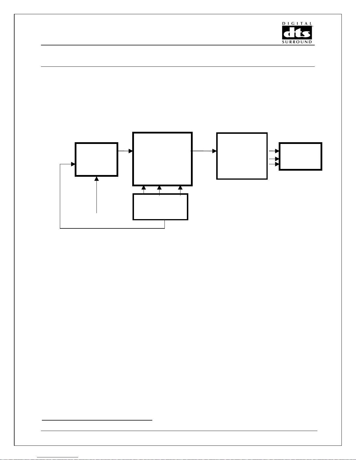
4.1 GENERIC SETUP
Figure 4.1.1 outlines the minimum system elements req uired for DTS encoding using t he CAE-
4.
TC
AES OUTPUT DEVICE
E175
L/R C/SUBLS/RS
DVD
L/R
TC
CAE-4 ENCODER
BITSTREAM
AES IN PU T
B itstream capture
W orkstation
C/SUBLS/RS
Figure 4.1.1 G en eric E ncoding S etup
First, source material must be supplied to the encoder as three AES/EBU digital inputs plus
time code. The encoded bit stream is then sent to an AES digital bitst eam capture workst ation.
As the following examples illustrate, the source material can be provided f rom digital recorders
and digital audio workstations. The recording device is typically a digital audio workstat ion such
as a PC compatible computer equipped with a digital input audio car d.
Revision 2.2 Page 9
Page 14

Figure 4.1.2 shows a test set up using industry standar d equipment.
DA88
TC
TDIF
E175
DVD
L/R C/SUB
TDIF
IF88 AE
LS/RS
L/R
TC
CAE-4 ENCODER
BITSTREAM
BITSTRE A M
DTS CAD-4 5.1 DECODER
1/2 5/63/4
AES METER BRIDGE
C/SUBLS/RS
C/SUBL/R LS/RS
Figure 4.1.2 Test Set Up with DA88 Source
The TDIF output of a Tascam DA88 is converted by a Tascam I F88AE into the three AES/EBU
channels required by the encoder; L/R, LS/RS, C/SUB. The T C OUT of the DA88 is connected
to the E175directly to the Encoder TC IN. T he BITSTREAM OUT of the encoder is connected
to the DIGITAL INPUT of the DTS CAD-4 Decoder where it is converted back into L/R, LS/RS,
C/SUB AES formatted outputs. These thr ee outputs are monitored by an AES Meter Bridge.
The six analog audio outputs are connected to a 5.1 audio monitor for audible evaluation.
Revision 2.2 Page 10
Page 15

The TDIF output of a Tascam DA88 is converted by a Tascam I F88AE into the three AES/EBU
channels required by the encoder; L/R, LS/RS, C/SUB. The T C OUT of the DA88 is connected
to the E175 and then directly to the encoder TC I N. The BITSTREAM OUT of t he encoder is
connected to the DIGITAL INPUT of the DTS CAD-4.5.1 Studio Decoder where it is converted
back into L/R, LS/RS, C/SUB AES f or mat ted output s. T hese th ree output s are m onitor ed by an
AES Meter Bridge. The six analog audio outputs are connected to a 5.1 audio monitor for
audible evaluation.
To operate the test setup, per form the following steps af t er cabling as shown in the diagram.
• Turn on power to encoder.
• Load source material onto the DA88. Source material must be 48k to allow DVD
encoding or 44.1k to allow CD encoding.
• Select LFE ON or LFE OFF.
• Select surround 0db or -3db.
• If DVD (48k) source material is being used, select high or low encoding rat e. CD source
material (44.1k) will always be encoded at 1234kbps.
• Select TC BYPASS/TC TRIGGER
• Press Reset
The audio from the DA88 which has been encoded then decoded will now be available at the
meter bridge and the monitor s .
Figure 4.1.3 shows a DA88 source and an IBM Compatible work station with a Sek’d PRODIF
96Pro digital sound card as a recorder.
If the encoder is set to “TC Trigger,” one mu st enter START and END time on the E175 (per
item 6.3)
A simple recording session with this setup and the DTS Record Panel software (ref erred to as
the Panel) is now described:
• Run the Panel (See Section 5 for set-up overview) on the PC.
• Open the Project menu. Define a path and name for the proj ect. The output f ile which
is eventually recorded will be assigned a name automatically.
• Click on setup. Set source to desired device. Select desir ed input source.
• Select the desired encoder settings on the front panel of the encoder.
• Press the encoder reset button.
• Click record on the Panel program .
• Press play on the DA88
• Click stop on the Panel program when all of the desired source material has been
encoded and decoded.
Revision 2.2 Page 11
Page 16

• Stop the DA88.
DA88
TC
TDIF
TDIF
IF88 AE
L/R C/SUB
LS/RS
L/R
TC
CAE-4 ENCODER
BITSTREAM
IBM COMPATI BLE
WORKSTATION WITH
AES/EBU SOUND CAR D
SUCH AS Sek'd Prodif
96Pro
C/SUBLS/RS
Figure 4.1.3 DA88 Source with PC W orkstation
• Select the bit depth and weather the surround are ES encoded.
• Click on CHECK on the Panel program . An edit box will summarize the Format , bit rat e,
start and stop time codes.
4.2 AUTHORING SYSTEMS SUPPORT
We are working to certify the following authoring systems for DTS. Contact your authoring
system provider if you have any questions regarding the inter face.
Daikin Scenarist
Spruce Technologies
Sonic Solutions
Sony
Toshiba
MEI
Revision 2.2 Page 12
Page 17

5 DTS Record Panel Software
C
5.1 OVERVIEW
The DTS record panel (PANEL) is provided to simplify the encoding check process. Start by
creating a directory called DTS Panel and copy all of t he programs into this f ile.
Information regarding selecting 16bit - 16bit ES, ect…descr ibing the meaning and use of .”dt s”
(padded file) “.cpt” (c om pact ed)
5.1.1 Panel
The Panel is a windows program capable of running on Windows 95, 98 and NT. The Panel
provides a method for recording or "capturing" the DTS Bitstream. Once captured, the
Bitstream can then be analyzed for dropouts and other syntax errors by using the check
function on the panel.
The edit function can then be used to proper ly format the bitsteam to accommodate the CD or
DVD authoring system, and can be used to trim t he beginning and end of the file as needed.
A project file (*prj ) is created that details all of the actions taken by the PANEL program. The
project file can be opened with.
The following sound cards have been verified to be compatible:
Lynx One ZEFIRO ZAZ MOTV 308/PCI324
SEK'D-PRODIF 96 Pro
Record/Stop
Trim
Setup
Select sound card
heck
Generate
.prj
(project
history)
File
Output
Options:
pad
.cmp
.wav
-Continuity
-Sync
-report 1
st
/last TC
-meta data header
-tc stamp video frame rate
-bit depth
Figure 5.0 Record Panel Process Flow
Authoring
Revision 2.2 Page 13
Page 18

5.1.2 Using Panel in CD Code (44.1)
Below is a description of the overall flow process for creation of DTS CD content. Note: it is
recommended to use an external program (Sound Forge, MS player or equivalent) to suppor t
playback of the .wav files. Future r elease of the Panel software will include a play panel.
Bitstream capture PC
DA88
5.1 Master
CAE-4
Sound
card
Sound
Forge, MS
media
player or
Play
Panel*
DTS
DLT
Authoring
Record
Panel
.wav
file
Figure 6.0 CD content Process Flow
5.1.2 Optional Dos Utilities
5.1.2.1 DTS Expand
The DTSExpand is a DOS program. T his program will create a new padded (*.DTS) f ile f rom a
compacted (*.CPT), and file outputs a padded file.
Compacted file DTS Expand Padded
Syntax Expand path:\file.(source) name.cpt pat h:\(output) filename. dt s.
The Expand program will require the frame size information listed below:
Prompt for the source file DTS framesize
Rate(kbps)
Revision 2.2 Page 14
Compacted Frame Size
1509.25 2013
754.50 1006
Page 19

5.1.3.2 DTSbin2wave
DTS 2Bin is a DOS program. The bin2wave will convert a padded file to a wave file.
padded bin2wave wav file
5.1.3.3 DTS2CPT
Syntax DS2cpt path : (“source”) filename.dts path:\( output) filenam e.cpt. DTS2cpt will create a
new padded (*.dts) file compacted (*.cpt) file.
Revision 2.2 Page 15
Page 20

6 E175-01 DVD Timecode Controller
6.1 E175-01 DVD FEATURES
• Starts/Stops the Encoder on user specified time
• Runs on a valid SMPTE time code input
• Accepts all standard frame rates 29.97/30ndf, 29.97df, 25df and 25f.
• All settings are saved in non-volatile memory
• The unit may be mounted into a 19 inch equipment r ack or be placed on a desktop.
6.1.1 Interface I/O
6.1.2 Power
• Connect mains to AC power adapter. Connect the 9VDC output of the converter
labeled +9VDC 500ma (Note: center pin is +9V and the outside ring is ground) into
the rear of the E175-01 DVD. At tach a chassis ground to the rear of the unit or if
rack mounted verify chassis ground continuity.
6.2.2 Signal
• Plug a ¼” jack (st ereo or mono) from the tim e code source to the “time code input
#1” rear input jack.
Signal Name
Time Code High Tip Tip
Time Code Low Ring Sleeve
Shield Sleeve
• Plug the “time code output” ¼” jack (provided) from the E175DVD to the CAE-4 Time
code input.
• Note: The only functional I/O on the E175DVD is the time code input and time code
output#1.
Using TRS Plug) (Using A ¼” Phono Plug)
Revision 2.2 Page 16
Page 21

6.2 SETUP & INITIALIZATION
When f irst applying power, the E175DVD with show the current r evision for about five seconds
and then default to a menu (Start or End) . If this does not occur f or any reason the processor
can be reset by disconnecting and then reconnecting the main power. After f ive seconds the
display should look
like:
Setting the Start time:
Press the DISPLAY button until the following is displayed on the lower line.
??:00:00:00 Start
00:00:00:00 Gen 30
01:00:00:00 Start
§ Press the SET button.
§ Press the right arrow to change the cursor position (blinking digit).
§ Press the up arrow to increase the value or DI SPLAY+up ar r ow to decrease the value.
§ Press the DISPLAY + Right arrow to zero the display. Press store when all entries are
complete.
ENCODING
aaaa
R
R ∅∅∅∅ ñ
Below is an example of a valid 1 hour start time:
01:00:00:00 Start
RR
SET STORE DISPLAY
• Upon the first power up out of the box, memory initialization may be req uired. If any of
the display locations show a “????”, then zero out the display before entering numeric
start/stop data.
NOTE: When k eeping the DISPLAY button pressed and then pressing the up button
scroll the numbers in the reverse direction. Also, keeping the up button pressed will cause the
numbers to auto increment.
ñ
ññ
one can
• Upon achieving the correct start time, pr ess “ STORE”.
• Then press the “DISPLAY” until the “end” t im e appear s.
• Repeat the step above for inputting the “end” time. T hen depress “STO RE” to save the
end time.
6.3 FUNCTIONAL DESCRIPTION
When the incoming time code matches the stored “Star t” time, the green encoding status LED
with turn on and stay on until the end time is reached. The top line of the display indicates t he
actual time code output of the E175-01 DVD. The Encoder will trigger while in “TC TRIG”
position, when the E175-01 DVD passes the “Start” tim e ( green LED on).
Revision 2.2 Page 17
Page 22

The Encoder needs to be in a pre-trigg er reset mode befor e the E175DVD reaches the “Start ”
time. Before the E175DVD star t point the Encoder TC LED with blink fast (15Hz) then at the
trigger point t he TC LED will blink slow (5Hz) and the READY LED will be solid on.
The upper right hand corner of the display indicates the frames per second (ie; 30, 25, dp)
Revision 2.2 Page 18
Page 23

7 CAD-4 Professional Decoder
7.0 SET-UP
7.1 MAINS POWER
On the side of the chassis you will find a mains power selector switch. Verif y the switch is in
the correct position for you region. Slide to the 230V position or the 115V position.
7.2 INTERFACE
7.2.1 Inputs
There is a choice of 3 inputs available, these are O ptical, 75 ohm or Balanced Digital (XLR).
Press the digital input selector switch IN f or 75 ohm O R press the dig ital input selector OUT for
Balanced Digital (XLR).
7.2.2 Digital Outputs
The 3 AES/EBU outputs are paired as: Cent er / Sub, SurrR/SurrL, Right/Left
7.3.3 Analog Outputs
All analog outputs are balanced XLR.
7.3 STATUS INDICATORS
The Power status monitors the presence of Mains power. The DTS status monitors the
presents of a DTS decoded output. The Lock status detects an incoming DTS bitstream.
Revision 2.2 Page 19
Page 24

Appendix A
Time code embedding specifications
32 Bytes timecode
header
32 Bytes timecode
header
DTS frame data
2013 bytes for 1.51MBps
DTS frame data
1006 bytes for 754kBps
3 null
bytes
1010 null bytes
754kbps
00000000
00000010
00000020 7FFE 8001 FC3C 3ED2 75E0 OD3A OOD9 8C53 ….
00000030 189C E739 8000 002D B6DB 6DFF FFFF FFFF …9.
00000040 FFFF FFFF FFFF FFFF FFFF 44D0 OOD0 DOD0 .t..
00000050 0074 1000 1DO0 00D5 OOD5 OOD5 BBDB O49D B..,
00000060 1209 C22C C2BD 3516 1039 707B 749B AFBF
00000070 5E34 8888 8868 6856 4466 4235 12AF 28C8
00000080 8A86 6888 4834 F2D0 EECC CACC CAC8 A693
00000090 108C EAA4 6844 2422 4432 FOCA EAA4 4842
F872 4E1F OOO2 0060 00D1 0014 0053 0023
0566 OO11 OOOO OOO0 F872 4E1F OODB 1F70
.rN.
.f..
000000A0 2222 4220 OOO0 OOO0 OOD0 OOD0 OOD0 00D0
000000B0 EA80
A1.0 DTS Bitstream Time code Embedding Specif ication
The purpose of this specification is to define how the DTS bitstream incorporates time code
embedding (time stamping) into a single bit stream. The majority of this information is
extracted from the Advanced Television Systems Committee standard describing time code
stamping and is consistent with the physical and logical IEC958 interface specification.
Time code embedding indicates the absolute time at which the encoded audio samples are
taken. The time code is encoded as values of SMPTE tim e code.
Revision 2.2 Page 20
Page 25

Coding of preamble
The data to be transmitted is formed into bursts of data. A 64-bit preamble is added to the
beginning of each burst. The remainder of the burst is then the data payload. The preamble
occupies 16 bits in each of 4 sub-fram es. The preamble is considered t o be four 16-bit words
designated as Pa, Pb, Pc, Pd. The contents of these f our words are specified in T able 1. When
placed into a sub-frame, the MSB of a 16-bit preamble word is placed into time slot 27, and the
LSB is placed into time slot 12. The combination of Pa and Pb form a 32-bit sync code. This
allows a receiver to find the preamble with a very small probability of mis-detection.
Table 1 Preamble Words
Preamble word Contents
Pa 16 bit sync word 1 = 0xF872
Pb 16 bit sync word 2 = 0x4E1F
Pc 16 bit burst_info value.
16 bit length_code (unsigned integer), equal to
Pd
the number of data bits in the following data burst
32-bit mode
The 4 preamble words are contained in 2 sequential frames. The frame beginning the data
burst contains preamble word Pa in the Ch1 sub-frame, and Pb in the Ch2 sub-f rame. The next
frame contains Pc in Ch1 and Pd in Ch2.
16-bit mode
The 4 preamble words are contained in 4 sequential sub-f rames of the individual channel (Ch1
or Ch2) being employed to convey the DTS data stream. The sub-frame (of the channel being
used) beginning the data burst cont ains preamble word Pa, the next sub-f rame ( of t he channel)
in the burst contains Pb, etc.
burst_info
The 16-bit burst_info value contains information about the data which will be found in the burst.
The contents of burst_info is specified in Table 2. Bit 15 of burst_info is considered the MSB.
Table 2 burst_info
Bit(s) Value
0-4 Data_type (5-bit unsigned integer = 0- 31)
5-6 Reserved (shall be set to ‘00’)
Error_flag 1 indicates data burst may contain
7
errors, 0 indicates data may be valid
8-12 Data_type_dependent
13-15 Data_stream_number
Revision 2.2 Page 21
Page 26

data_type
The 5-bit data_type field indicates what type of data, (DTS, time st am p, etc.) will be found in the
burst. Three values of data_t ype are defined in this specification. See T able 3.
Table 3 Values of data_type
Value Meaning
0 Null data
1 DTS data
2 Time Stamp
3-31 Reserved
Reserved bits
Bits 5 and 6 are reserved. These bits shall be set to a value of ‘00’. Receivers of this data
stream may ignore the contents of these bits.
error_flag
The error_flag bit is available to indicate if the contents of the bur st contains data errors. If a
data burst is thought to be err or free, or if the data source does not know if the data contains
errors, then the value of this bit shall be set to a ‘0’. If the data source does know that a
particular data burst contains some errors this bit may be set to a ‘1’. The use of this bit by
receivers is optional.
data_type_dependent
The data_type_dependent field contains 5 bits whose meaning is intended to be dependent on
the value of data_type.
data_stream_number
The 3-bit data_stream_number indicates t o which virtual data stream the burst belongs. Eight
codes (0-7) are available so that up to eight independent data streams (each of any assigned
data type) may be carried in the IEC958 data stream in a time multiplex. Each independent dat a
stream shall use a unique value for data_str eam _type.
In the consumer application the following constraints shall apply. If a single data stream is
carried, the value of data_stream_num ber shall be 0. If a set of dat a streams are carried, one of
the streams shall have a data_stream_number of 0. If a receiver is only capable of selecting
and processing a single data stream, it shall receive and process data_stream_number 0.
Stream 0 thus has the highest priority, and should carry the most important data. The MSB of
the 3-bit stream number is placed in bit num ber 15.
length_code
The length_code indicates the length of the data payload in bits, from 0 to 65535. The size of
the preamble is not counted in the value of length_code.
Revision 2.2 Page 22
Page 27

Burst spacing
In order to facilitate t he implementation of the aut odetection function there is one r equirement
on burst spacing. T here shall not be a seq uence of 4096 or m ore IEC958 f rames which contain
at least one data burst, without the beginning of at least one of the dat a bur sts preceded by two
IEC958 frames which have sub-frame contents in time slots 12-27 of all 0’s. Since the subframe contents of t ime slots 12-27 are set to all zeros between data burst s, this req uirement is
automatically met unless there are sequences of data bursts so tightly packed that there is
never (in a span of 4096 IEC958 frames) a sequence of 2 all-zero frames preceding any burst.
The null data_type
A null data type is provided so that the preamble sync codes may be inser ted occasionally into
the data stream. This could potentially enhance reliable autodetection of whether or not the
sub-frame contains PCM audio or digital data.
The null burst data_type has a value of 0x0. In a null data burst , the length_code, error_flag,
and data_type_dependent values shall all be set to ‘0’. The data_stream_number shall be set to
0x7.
If the burst frequency of the data being conveyed is low, or the interface is idle (no data to
convey) there may be long periods of inactivity which may be autodetected as PCM silence.
Placement of null data bursts allows sync codes to be detected, allowing an autodetector to
realize that the sub-frame content s should be considered to be data and not PCM audio. Thus
use of null data bursts is optional.
The DTS data_type
When DTS data is conveyed, data_type has a value of 0x1. In this case, the value of
data_type_dependent shall be as shown in Table 4.
Table 4 Values of data_type_dependent When data_type = 1
burst_info bit
number
Data_type_dep
endent bit
Meaning
number
8-10 0-2 Value of bsmod in DTS
elementary stream
11-12 3-4 Reserved, shall be set to ‘00’
The DTS syntactical element bsmod is a 3-bit f ield. The left-m ost bit of this value is placed in
burst_info bit number 10. Receivers m ay ignor e the contents of the reserved bits.
Placement of DTS frames into data bursts
The DTS data stream consists of a sequence of DTS sync frames. Each DTS sync frame
represents 1536 encoded audio samples. DTS sync fram e boundaries occur at a frequency of
exactly once every 1536 IEC958 frames. Each burst of DTS data shall contain one complete
DTS sync frame. The leng th of the DTS data burst will depend on the encoded bit rate (which
determines the DTS sync frame length). The data bursts containing DTS sync frames shall
occur at a regular rate, with each DTS bur st beginning 1536 IEC958 f rames af ter t he beginning
of the preceding DTS burst (of the same data_stream_num ber ) .
Revision 2.2 Page 23
Page 28

1.4.2 The time stamp data_type
A
Time stamps are useful in applications where time inf ormation must be k ept closely associated
with encoded audio data (see Figure 1).
Values of SMPTE time code occur only once per picture fr ame, and thus have a resolution in
their value of approximately 33 ms (for 30 Hz frame rate). Audio samples occur much more
frequently, approximately once every 21 µs (48 kHz sample rate). The DT S audio access units
occur every 32 ms (48 kHz sample rate).
udio Signals
to be encoded
DTS CAE-4 Encoder
SMPTE
Time Code
DTS-Bitstream
Coded audio + time code
Figure 1. Encoding audio wi t h t i me code.
1.4.3 Preamble values
Time stamps are conveyed by data bursts with a data_type value of 0x2. The value of
data_type_dependent shall be set to 0x0 for the payload defined below. (In the future, other
payload types may be defined for different values of data_t ype_dependent.) The length_code
shall indicate the actual length of t he time stamp payload.
Time stamp payload
The time stamp payload, shown in Table 5, has a minimum length of six 16-bit words which
have a defined meaning. Additional 16-bit words may be optionally added, but the meaning of
these words is not specified.
Revision 2.2 Page 24
Page 29

Table 5 Time Stamp Payload
Time Stamp MSB Bit Number LSB
Payload Word 15 14 13 12 11 10 9 8 7 6 5 4 3 2 1 0
0
Usr8, Usr7, Hours
1
Usr6, Usr5, Minutes
2
Usr4, Usr3, Seconds
3 Usr2, Usr1, cf, df,
Frames
4 Sample Number S15 S14 S13 S12 S11 S10 S9 S8 S7 S6 S5 S4 S3 S2 S1 S0
5 Reserved, Flags R R R R R R R R R R a3 a2 a1 a0 f1 [10]
[63] [62] [61] [60] [55] [54] [53] [52] [59] [58] H20 H10 H8 H4 H2 H1
[47] [46] [45] [44] [39] [38] [37] [36] [43] M40M20M10M8 M4 M2 M1
[31] [30] [29] [28] [23] [22] [21] [20] [27] S40 S20 S10 S8 S4 S2 S1
[15] [14] [13] [12] [7] [6] [5] [4] [11] [10] F20 F10 F8 F4 F2 F1
Table Entries
[63] Bit number 63 of SMPTE time code word
H20 This bit has a value of 20 hour s
R Reserved bit, set to ‘0’
Usr8 The 8th g roup of user bits in the SMPTE time code word
cf Color frame flag bit
df Drop-frame f lag bit
f1 Flag bit number 1
S15 Sample number, bit 15
a3 Frame rate code, bit 3
The first four words contain an hours, minutes, seconds, frame count. Space is available to
carry the user group, color frame flag, drop f ram e f lag, and unassigned bit s f r om a SMPTE time
code word. Flag bit f1 (in word 5) is set to a ‘1’ if this information has been copied from a source
of SMPTE time code into the upper bits of payload words 0-3. If flag bit f1 is set to a ‘0’, this
information has not been provided, and the upper bits of payload words marked [ ] ar e all set to
‘0’. T he sample number in word 4 is an unsigned integer which indicates the sample number
(Sn in Figure 2) to which the time code value applies. The sample number does not have to be
exactly correct, but should indicate an audio sample within ±0.5 ms of the ideal value. Word 5
contains 10 reserved bits (in bits 6-15), a 4-bit frame rate code (a3-a0) , the f1 f lag bit, and t he
drop-frame f lag bit (bit 10 of the SMPTE time code word) if the tim ing source is SMPTE time
code. The dr op-frame f lag bit is always provided in bit 0 of word 5; its presence in bit 6 of word
3 is conditional on the value of the f1 f lag bit. The meaning of the frame rate code is shown in
Table 6.
Revision 2.2 Page 25
Page 30

Increasing Time
TS
n
Time Stamp n contains the
tim e info rma tion fo r sa mple
S n in D T S fra me n
DTS Frame n
Sample Sn Sample Sn+1
If the value of sam ple number Sn contained in tim e
stamp n is >= 1536 (the num ber of sam ples in an DT S
frame), it points to sample 1536-Sn in DTS frame n+1
Figure 2. Time stamps and DTS frames in the IEC958 data stream.
Frame Rate Code Frame Rate
a3 a2 a1 a0
0 0 0 0 not indicated
0 00124 ÷ 1001 (23.98)
0 01024
Table 6 Frame Rate Code
TS
n+1
Time Stamp n+1 contains the
tim e in fo rmat ion fo r s a m p le
Sn+1 in DTS fram e n+1
DTS Fram e n+1
0 01125
0 10030 ÷ 1001 (29.97)
0 10130
0 11050
0 11160 ÷ 1001 (59.94)
1 00060
- ---reserved
1 111reserved
Additional payload words containing arbitrary information may be optionally provided. The
meaning of any additional payload informat ion is not specified. Receivers should be capable of
operating whether or not additional information is present. The presence of additional
information may be determined by the value of the length_code in the burst preamble. If the
value length_code is 0x0060 then no additional information is present. If the value of
length_code is greater than 0x0060 then additional information is present.
Revision 2.2 Page 26
Page 31

Appendix B
Compacting files using the Join program
If for some reason, your DVD authoring system cannot use padded files, and you have access to a PC and can run a
DOS program, you can use the attached executable file to generate a compacted file directly from the padded file.
1) Place a copy of the Join program in the same folder as your source padded file.
2) In DOS, navigate to the folder with the files.
3) Type Join, then press enter key.
4) Enter the code for the frame rate.
5) At the File 1 prompt, enter the source file name, with extension.
6) At the File 2 prompt, enter the word end (lower case).
7) Enter a new output file name.
8) Enter DVD frame size - for 754 kbps, 1006; for 1509 kbps 2013.
9) Enter sample rate - 48000.
10) Enter sample frame size - 512.
11) Enter time code trigger position, the time code position where the source file starts. Get this information at the
end of the *.prj file where the output file information is
12) Enter the time code start position, where you need the output file to start from. At this point you may select to
start from a point after the trigger point.
13) Enter the end time, where you want the output file to stop. At this point you may select to stop the file at a point
earlier than the end of the source file.
It should be noted that on some versions of Microsoft NT a line entry bug occurs. The first typed letter will be
ignored. Please watch the entry line to insure that your typing appears on the screen.
No problems exist with any other Microsoft operating systems.
Editing files using the Join program
If for some reason, a continuous file needs to be created from, and you have access to a PC and can run a DOS
program, you can use the attached executable file to generate a compacted file directly from the padded file.
1) Place a copy of the Join program in the same folder as your source padded file.
2) In DOS, navigate to the folder with the files.
3) Type Join, then press enter key.
4) Enter the code for the frame rate.
5) At the File 1 prompt, enter the PART 1 source file name, with extension.
6) At the File 2 prompt, enter the PART 2 source file name, with extension.
6) At the File 3 prompt, enter the word end (lower case).
7) Enter a new output file name.
8) Enter DVD frame size – 1006 for 754 kbps *.cpt files, 2013 for 1509 kbps *.cpt files, 2048 for padded *.dts files.
9) Enter sample rate - 48000.
10) Enter sample frame size - 512.
11) Enter time code trigger position for PART 1, the time code position where this source file starts. Get this
information at the end of the *.prj file with the output file information.
11) Enter time code trigger position for PART 2, the time code position where this source file starts. Get this
information at the end of the *.prj file with the output file information.
12) Enter the time code start position, where you need the output file to start from. At this point you may select to
start from a point after the trigger point.
13) Enter the end time, where you want the output file to stop. At this point you may select to stop the file at a point
earlier than the end of the source file.
It should be noted that on some versions of Microsoft NT a line entry bug occurs. The first typed letter will be
ignored. Please watch the entry line to insure that your typing appears on the screen.
No problems exist with any other Microsoft operating systems.
DTS Encoding System User Information
Revision 2.2 Page 27
Page 32

Further clarification in reg ards to the bitstream capture computer conf iguration is
provided with in this notice.
• The system must be equipped with separate system and data hard drives. The
bitstream will be recorded to the separate data drive. A partitioned drive will not
work efficiently and will probably cause dropouts while recording . There must be
sufficient space for workspace and generated f iles. It is sugg ested t hat no sm aller
that a 4 GB drive be used. The drive should be rated f o r m ultimedia applications.
• Only one sound card should be installed in the PC and it should not be sharing its
IRQ with another card.
• Certain types of video cards can take over data tr ansfers on the bus. If possible,
an AGP video board should be used, as these do not rob resources from data
transfers. If this is not possible and dropouts occur, the display should be set to
its minimum perform ance set ting (usually VGA).
• All background programs need to be set to off. This includes virus scans, screen
savers, etc.)
• Frequently, in the CMOS setup, there is a switch that can be set for allowing or
disallowing interrupts during writing. T his should be set so that writing data to the
hard disk is not interrupted. The wording for this varies machine to machine.
Revision 2.2 Page 28
 Loading...