

Page 1
ALCHEMY 5
USER’S MANUAL rel. 1.3 GB
Page 2

2
Le informazioni contenute in questo documento sono state attentamente redatte e
controllate. Tuttavia non è assunta alcuna responsabilità per eventuali inesattezze.
Tutti i diritti sono riservati e questo documento non può essere copiato, fotocopiato,
riprodotto per intero o in parte senza previo consenso scritto della D.T.S .
D.T.S. si riserva il diritto di apportare senza preavviso cambiamenti e modifiche
estetiche , funzionali o di design a ciascun proprio prodotto. D.T.S non assume alcuna
responsabilità sull’uso o sull’applicazione dei prodotti o dei circuiti descritti.
The information contained in this publication has been carefully prepared and
checked. However, no responsibility will be taken for any errors. All rights are
reserved and this document cannot be copied, photocopied or reproduced, in part or
completely, without prior written consent from D.T.S.
D.T.S. reserves the right to make any aesthetic, functional or design modifications to
any of its products without prior notice. D.T.S. assumes no responsibility for the use or
application of the products or circuits described herein.
Les informations contenues dans le présent manuel ont été rédigées et contrôlées
avec le plus grand soin. Nous déclinons toutefois toute responsabilité en cas
d'éventuelles inexactitudes. Tous droits réservés. Ce document ne peut être copié,
photocopié ou reproduit, dans sa totalité ou partiellement, sans le consentement
préalable de D.T.S.
D.T.S. se réserve le droit d'apporter toutes modifications et améliorations esthétiques,
fonctionnelles ou de design, sans préavis, à chacun de ses produits. D.T.S. décline
toute responsabilité sur l'utilisation ou sur l'application des produits ou des circuits
décrits.
Las informaciones contenidas en este documento han sido cuidadosamente
redactadas y controladas. Con todo, no se asume ninguna responsabilidad por
eventuales inexactitudes. Todos los derechos han sido reservados y este documento
no puede ser copiado, fotocopiado o reproducido, total o parcialmente, sin previa
autorización escrita de D.T.S.
D.T.S. se reserva el derecho a aportar sin previo aviso cambios y modificaciones de
carácter estético, funcional o de diseño a cada producto suyo. D.T.S. no se asume
responsabilidad de ningún tipo sobre la utilización o sobre la aplicación de los
productos o de los circuitos descritos.
Page 3

3
INDEX:
1 - SYMBOLS ................................................................................................................ 4
2 - GENERAL WARNING ............................................................................................. 5
3 - GENERAL WARRANTY CONDITIONS ................................................................... 5
4 - TECHNICAL FEATURES ........................................................................................ 6
5 - ACCESSORIES ....................................................................................................... 8
6 - IMPORTANT SAFETY INFORMATION ................................................................... 9
6.1 Fire prevention...................................................................................................... 9
6.2 Prevention of electric shock .................................................................................. 9
6.3 Safety ................................................................................................................... 9
6.4 Level of protection against the penetration of solid and liquid objects ................ 10
6.5 Waste Electrical and Electronic Equipment (WEEE) directive ............................ 10
6.6 Long-life auto-charging buffer battery ................................................................. 10
7 - RETRACTABLE TOP HAT .................................................................................... 10
8 - EZ-SHELL .............................................................................................................. 11
9 - PAN / TILT LOCK .................................................................................................. 12
10 - VOLTAGE AND FREQUENCY ............................................................................ 12
11 - INSTALLATION ................................................................................................... 13
11.1 Safety cable ...................................................................................................... 14
11.2 Protection against liquids .................................................................................. 14
11.3 Movement ......................................................................................................... 14
11.4 Risk of fire ........................................................................................................ 14
11.5 Forced ventilation ............................................................................................. 14
11.6 Ambient temperature ........................................................................................ 14
12 - MAINS CONNECTION ......................................................................................... 15
12.1 Protection ......................................................................................................... 15
13 - DMX SIGNAL CONNECTION .............................................................................. 16
13.1 DMX addresses ................................................................................................ 17
13.2 Selecting the DMX address .............................................................................. 17
14 - ART-NET / SACN SIGNAL CONNECTION ......................................................... 18
14.1 Direct Ethernet operation .................................................................................. 18
14.2 Ethernet to RDM/DMX operation ...................................................................... 19
15 - RDM FUNCTIONS ............................................................................................... 20
16 - FIRMWARE UPDATING ...................................................................................... 23
17 - DISPLAY FUNCTIONS ........................................................................................ 24
18 - ERROR MESSAGES ........................................................................................... 32
19 - PERIODIC CLEANING ........................................................................................ 34
19.1 Lenses and reflectors ....................................................................................... 34
19.2 Fans and air passages ..................................................................................... 34
20 - PERIODIC CONTROLS ....................................................................................... 34
21 - DMX PROTOCOL ................................................................................................ 35
22 - FROST/COLOUR WHEEL ................................................................................... 73
Page 4
4
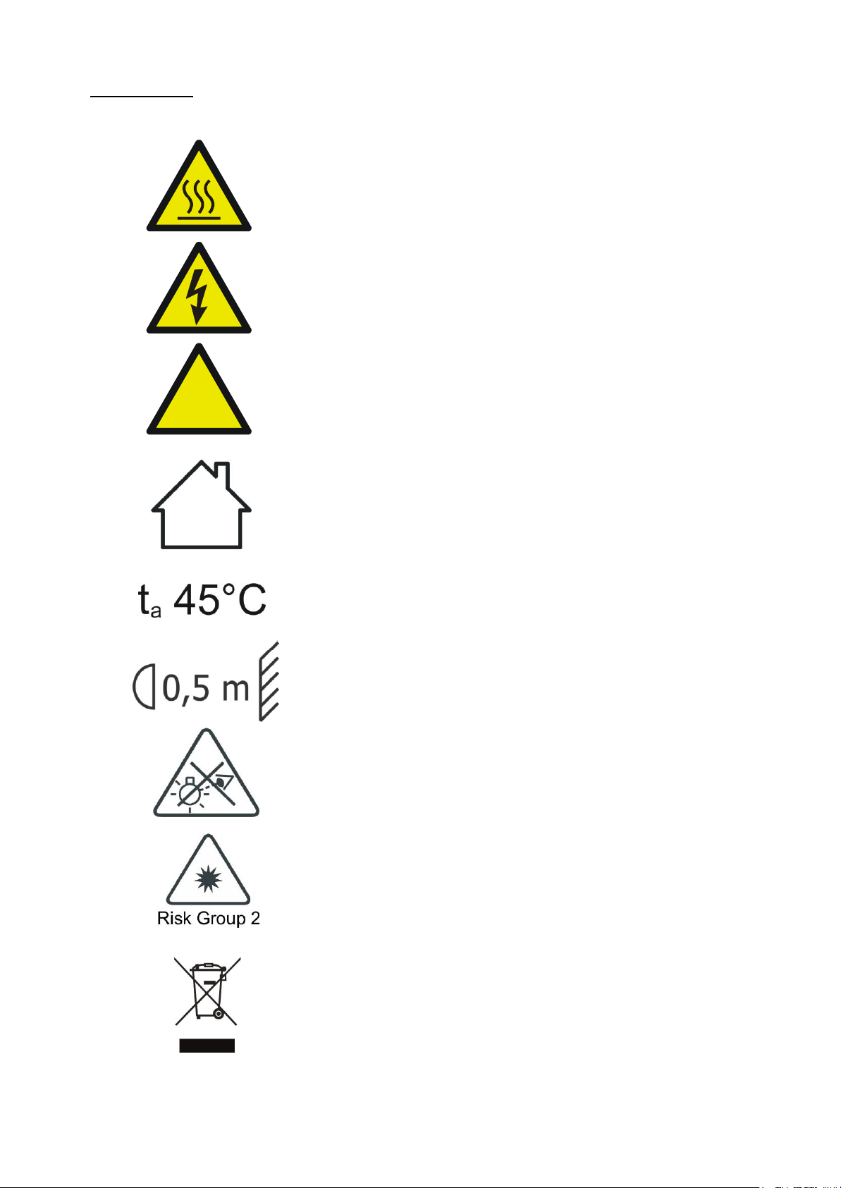
1- SYMBOLS
Graphic symbols used on this manual:
THIS SYMBOL INDICATES A HOT SURFACE
THIS SYMBOL INDICATES ELECTRIC
SHOCK RISK
THIS SYMBOL INDICATES GENERAL RISK
THIS SYMBOL MEANS “SUITABLE FOR
INDOOR USE ONLY”
THIS SYMBOL INDICATES THE MAXIMUM
OPERATING AMBIENT TEMPERATURE
THIS SYMBOL INDICATES THE MINIMUM
DISTANCE FROM THE OBJECTS AND THE
PEOPLE LIT BY THE LIGHT BEAM
THIS SYMBOL MEANS “DO NOT STARE
AT THE OPERATING LIGHT SOURCE”
THIS SYMBOL INDICATES
PHOTOBIOLOGICAL SAFETY
THIS SYMBOL INDICATES THE EUROPEAN
COMMUNITY DIRECTIVE 2012/19/EU ON
WASTE ELECTRICAL AND ELECTRONIC
EQUIPMENT (WEEE)
!
Page 5
5
2- GENERAL WARNING
Read the instruction contained in this user manual carefully, as they give important
information regarding safety during installation, use and maintenance.
The unit is not for household use and must be installed by a qualified electrician or
experienced person.
The device must always be equipped with an efficient ground connection.
3- GENERAL WARRANTY CONDITIONS
The unit is guaranteed for 36 months from the date of purchase against manufacturing
material defects.
The warranty covers defects in materials and workmanship. The warranty is not
appliable where a defect is caused by misuse or unauthorised repair of the product.
Any functional or/and physical modification of the product is not allowed.
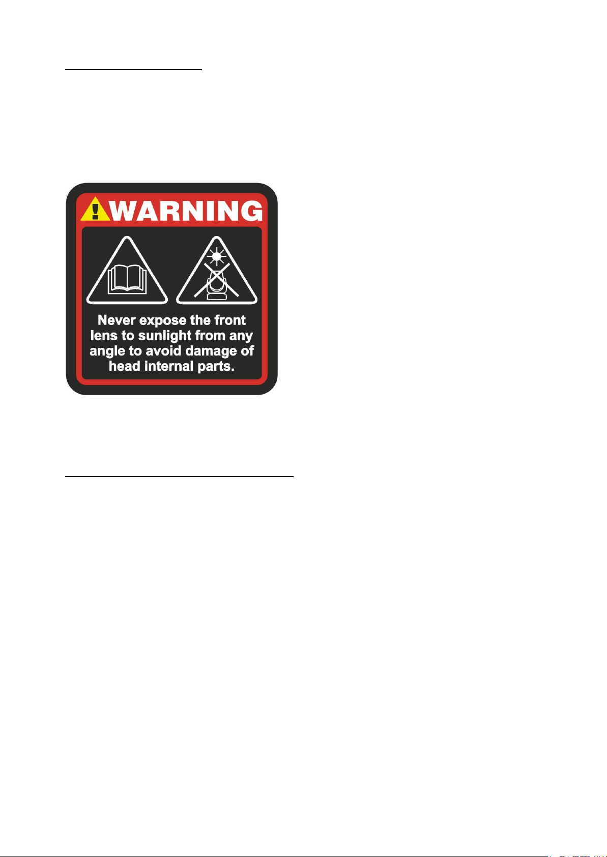
WARNING!
NEVER EXPOSE THE FRONT LENS
TO SUNLIGHT FROM ANY ANGLE
TO AVOID DAMAGE OF
HEAD INTERNAL PARTS.
Front lens could become powerful
magnifying glass if exposed towards the
sun or any strong artificial light source;
this can cause damage of head internal
parts, even for few seconds and even
when the unit is off.
The last command before switch off:
point the front lens down towards the
ground.
Page 6

6
4- TECHNICAL FEATURES
DTS Product Code:
03.MW009 ALCHEMY 5
OUTPUT
• Multi-chip LED source
• 10.800 Lumen output
• CRI: up to 98
• TLCI: up to 96
• LED lifespan: 20.000 hours (70% lumen output)
OPTICAL GROUP
• 10° - 47° linear zoom
• Ø 250 mm Fresnel lens
• Beam shaper (2x1 ratio) with endless rotation; indexable
• 2 frost filters (light and heavy) insertable via DMX
• Retractable ‘top hat’
COLOR GENERATION
• 6-color LED engine
• Linear CCT (1800K – 10000K)
• Linear ‘Green saturation’
• 100 gel filters emulation:
- Linear balance from gel filters emulation to white
- Linear balance between gel filters emulation
- True color of gel filters emulation at any CCT values
• Extra deep colors
• Color mixing by 6-color ‘Advanced’ mode
• Deep blue and Deep red filters (DMX-selectable)
DIMMER
• Hi-Q Dimming technology
• Tungsten emulation function (not yet implemented)
CONTROL
• Art-Net 4, sACN, RDM/DMX 512 protocols
Art-Net™ Designed by and Copyright Artistic Licence Holdings Ltd
• LCD graphic display + 4 soft keys; Auto-flip; Key-lock function
• ‘Standard’ and ‘Silent’ operation modes
- Noise level at Silent mode: 37 dBA @ 1 m (normal operation, full power)
• Internal operating system updatable via DTS dongle firmware uploader
• Li-Fe backup battery for controlling the display settings even when the unit is not
powered
Page 7

7
DMX
• 4 DMX modes:
- 1. CCT (default)
- 2. Advanced
- 3. Basic
- 4. Expo
PAN & TILT
• Pan 540° (3.8 sec.)
• Tilt 220° (2.1 sec.)
• 16-bit resolution
• Pan / Tilt lock
POWER SUPPLY
• Full-range 100-277Vac 50-60 Hz
• Power consumption: 450W max
• Power Factor: PF >0.90
CONNECTIONS
• Power supply: powerCON TRUE1 In/Out panel connectors
• DMX: XLR 3-pole and 5-pole In/Out panel connectors
• Art-Net / sACN: etherCON RJ45 panel connector
INTERNAL SAFETY DEVICES
Overvoltage and overtemperature circuits protection
OPERATING TEMPERATURE
-10° / 45°C
PHYSICAL
• IP20
• Weight: 26.5 Kg
• Finishing: Black
CERTIFICATIONS
Page 8
8
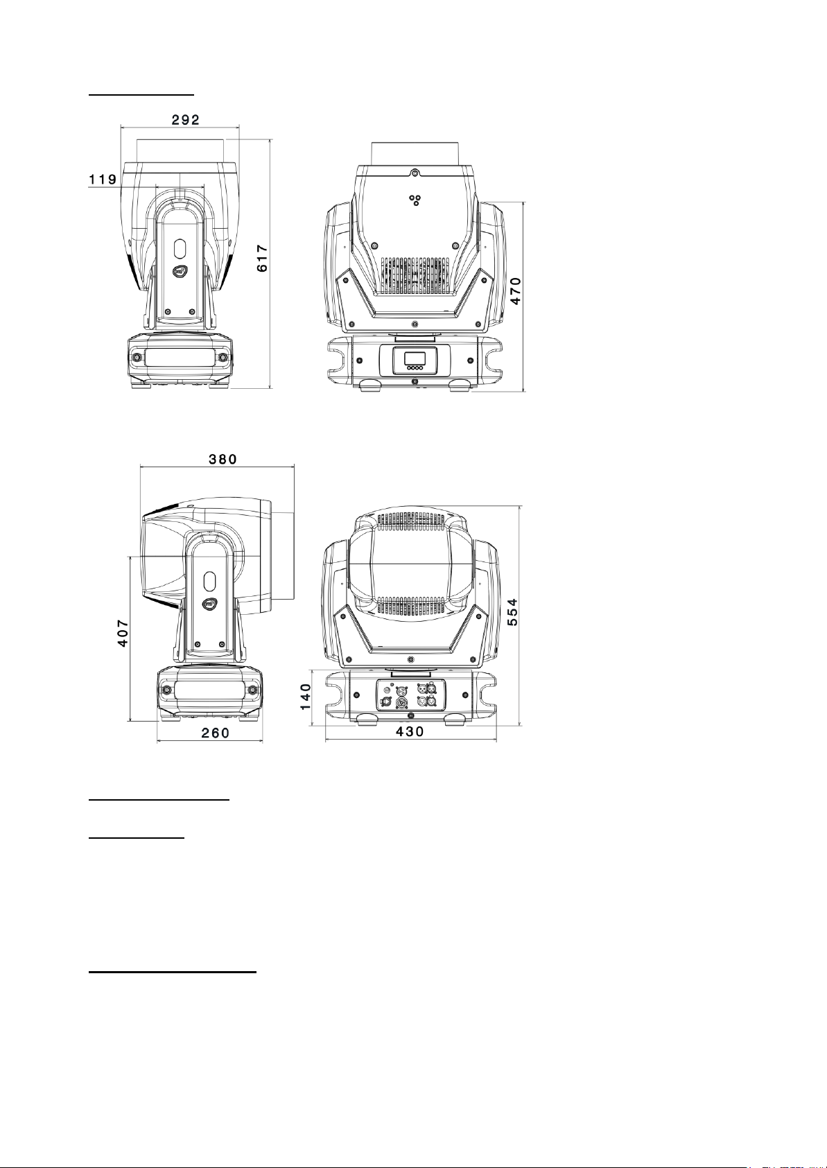
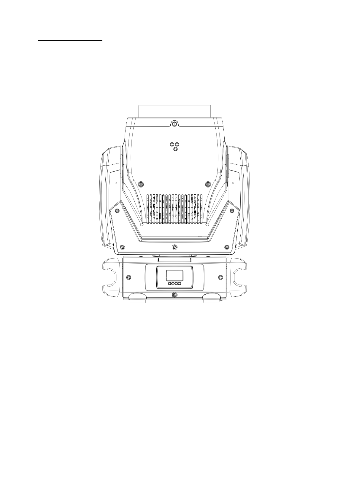
DIMENSIONS
5- ACCESSORIES
As standard
1 x Alchemy EZ-shell – 550x490x670 mm – 2 pcs needed in each flightcase (Code
0512K152.1)
1 x Cable with PowerCON TRUE1 female connector (Code 02K0012267.0015)
2 x Omega clamp with “Fast Lock” connection 1/4 turn (Code 02K00549)
1 x User’s manual
Optional (on request)
• Flightcase for 2 units (Code 0521C073)
• Aliscaf clamp for tube diameter 48-51 mm (Max load 200 Kg) (code 0521A033)
(indicated for any kind of loads vertical / horizontal)
• Professional Quick trigger clamp (Max load 100 Kg) (code 0521A037) (not indicated
for horizontal load)
• Safety cable 5 x 600 mm (Max load 60 Kg) (code 0521A038)
• DTS Dongle firmware uploader (code 03.LA.206
Page 9

9
6- IMPORTANT SAFETY INFORMATION
6.1 Fire prevention:
-Minimum distance from the objects and the people lit by the light beam: 0,5 m.
-Replace any blown or damaged fuses only with those of identical value (T 8A 250V).
Refer to the wiring diagrams if there is any doubt.
-Connect the projector to mains power via a thermal magnetic circuit breaker.
6.2 Prevention of electric shock:
-High voltage is present inside the unit.
Unplug the unit prior to performing any function which involves touching the inside of
the moving head.
-The level of technology inherent in the ALCHEMY 5 requires the assistance of
specialised personnel for all servicing. Please refer to an authorised DTS service
centre.
-A good earth connection is essential for proper functioning of the projector.
-Never connect the unit without proper earth connection.
-The fixture should be located in places with a good air ventilation.
6.3 Safety:
-Risk Group 2 product according to EN 62471.
CAUTION. Do not look directly into the light output and do not view the light beam with
optical instruments or any device that may concentrate the beam.
May be harmful to the eyes and skin.
-Do not stare at the operating light source.
-The luminaire should be positioned so that prolonged staring into the luminaire at a
distance of 38,9 m is not expected.
-The light source contained in this luminaire shall only be replaced by the
manufacturer or his service agent or a similar qualified person.
-The unit is not for household use and must be installed by a qualified electrician or
experienced person.
-The projector should always be installed with bolts, clamps and other tools that are
capable of supporting the weight of the unit.
-Always use a safety cable to sustain the weight of the unit in case of the failure of the
main fixing point.
-The external surface of the unit, at various points, may exceed 50°C. Never handle
the unit until at least 5 minutes have elapsed since the unit was turned off.
-Never install the fixture in an enclosed area lacking sufficient air flow.
The ambient temperature should not exceed 45°C.
!
Page 10
10
6.4 Level of protection against the penetration of solid and liquid objects:
-The projector is classified as an ordinary appliance and its protection level against the
penetration of solid and liquid objects is IP20.
Suitable for indoor use only.
6.5 Waste Electrical and Electronic Equipment (WEEE) directive:
- The projector, accessories and packaging should be sorted for environmental-friendly
recycling.
For EC countries: according to the European Directive 2012/19/EU for Waste
Electrical and Electronic Equipment and its implementation into national right,
luminaires that are no longer usable must be collected separately and disposed of in
an environmentally correct manner.
7- RETRACTABLE ‘TOP HAT’
The Top hat retracts automatically when projector is switched off.
To prevent damage, DTS recommend to press for 2 seconds any display button
to reset the Top hat position, before extracting the projector from the
packaging.
!
!
Page 11

11
8- EZ-SHELL
How to reuse foam EZ-shell:
1) Open 2) Extract cover 3) Extract unit
and accessories and EZ-shell
4) Each flight case can contain 5) Don’t forget to recycle
2 units and their EZ-shell
PLASTIC
PAPER
Page 12
12
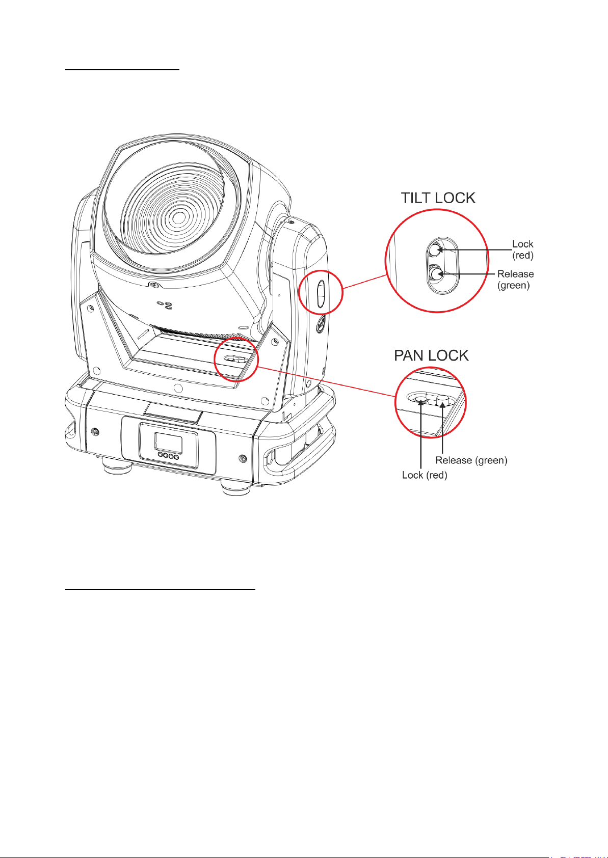
9- PAN / TILT LOCK
When moving or servicing the unit you can apply the Pan and Tilt lock.
To lock or release the Pan and Tilt refer to the picture below.
10- VOLTAGE AND FREQUENCY
ALCHEMY 5 operates at 100-240Vac 50-60 Hz.
Page 13
13
11- INSTALLATION
The unit is suitable for dry locations only.
ALCHEMY 5 may be either floor or ceiling mounted.
For floor mounting installations, ALCHEMY 5 is supplied with four rubber mounting
feet on the base.
For ceiling mounted installations, we recommend the use of appropriate clamps to fix
the unit to the mounting surface.
The supporting structure from which the unit is hung should be capable of bearing the
weight of the unit, as should any clamps used to hang it.
The structure should also be sufficiently rigid so as not to move or shake whilst the
ALCHEMY 5 is moving.
Four 1/4 turn Fast Locks connections placed in the base of the unit allow to hang the
ALCHEMY 5 by using two Omega brackets (provided in the box) in conjunction with
Aliscaf clamp (available on demand).
Page 14
14
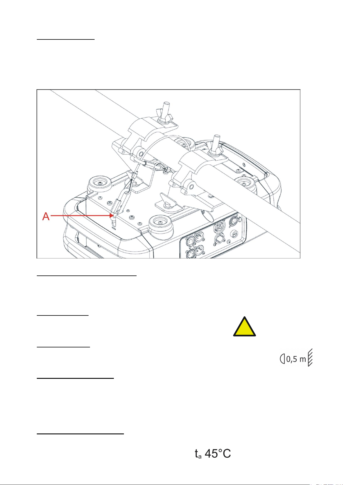
11.1- Safety cable
A safety cable must be securely fixed to the ALCHEMY 5 and to the suspension truss
in order to avoid the fixture accidentally falling should the main fixing point fail.
Make sure that the safety cable or chain can bear the weight of the entire unit.
A suitable safety cable (code 0521A038) is available on demand.
You may attach the safety cable to the attachment point (A) located on the base of the
fixture, as shown in the picture below.
11.2 Protection against liquids
The projector contains electric and electronic components which should under no
circumstances come into contact with oil, water or any other liquid.
The proper unit functioning would be compromised should this occur.
11.3- Movement
Pan: 540° rotation (3.8 sec.) ; Tilt: 220° rotation (2.1 sec.).
Do not place any object in the path of the projector’s movement.
11.4- Risk of fire
Each fixture produces heat and must be installed in a well-ventilated place.
Minimum distance from the objects and the people lit by the light beam: 0,5 m.
11.5- Forced ventilation
You will note, on inspection, that the unit features various air inlets and cooling fans
located on both the base and head of the fixture.
These should, under no circumstances, be blocked or obstructed whilst the projector
is in operation. Doing so could cause the fixture to seriously overheat thereby
compromising its proper operation.
11.6- Ambient temperature
The projector should never be installed in places that lack a constant air flow.
The ambient temperature should not exceed 45°C.
!
Page 15
15
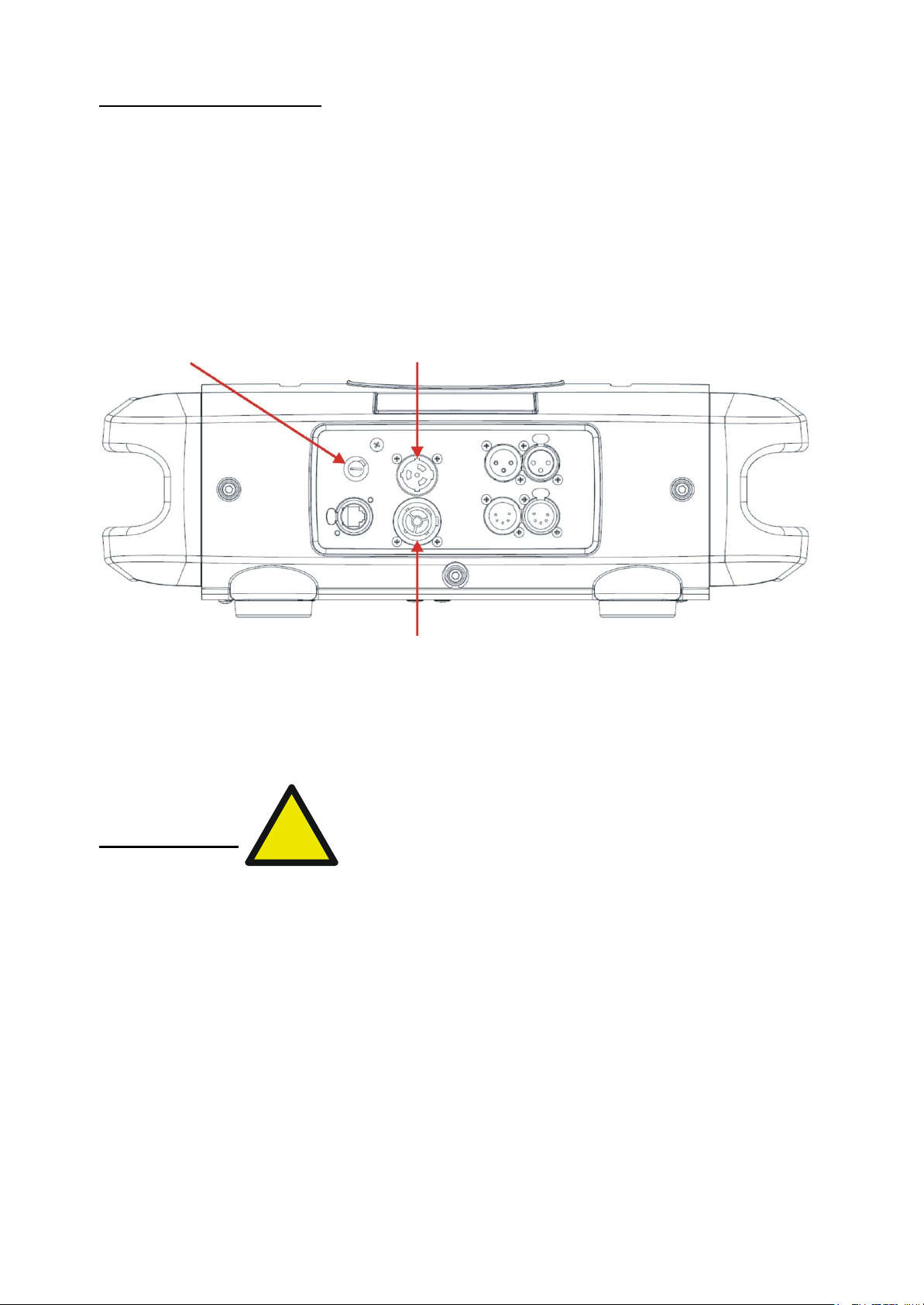
12- MAINS CONNECTION
ALCHEMY 5 operates at 100-240Vac 50-60 Hz.
Prior to connecting the unit to your mains supply, ensure that the model in your
possession correctly matches the mains supply available.
For connection purposes, ensure that your plug is capable of supporting 2,5 amps
at 230Vac or 5 amps at 100Vac each unit connected.
Strict adherence to regulatory norms is strongly recommended.
FUSE MAINS INPUT 100-240Vac 50-60 Hz
T 8A 250V PowerCon TRUE1 male panel connector
MAINS OUTPUT 100-240Vac 50-60 Hz (MAX 16A)
Max 6 ALCHEMY units @ 230Vac
Max 3 ALCHEMY units @ 100Vac
PowerCON TRUE1 female panel connector
11.1- Protection
The use of a thermal magnetic circuit breaker is recommended for each ALCHEMY 5.
A good earth connection is essential for the correct operation of the projector.
!
Page 16
16
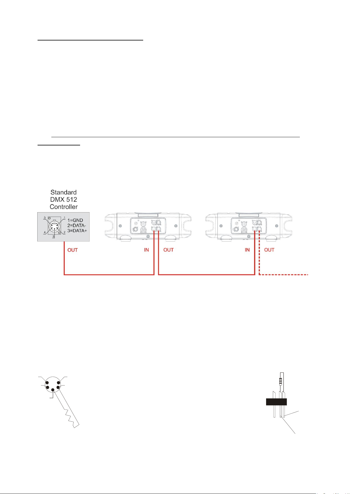
13- DMX SIGNAL CONNECTION
The unit operates using the digital DMX 512 signal.
Connection between the mixer and the projector or between projectors must be carried
out using a two pair screened ø 0.5 mm cable and a XLR 5 or 3 pins connector.
Ensure that the conductors do not touch each other.
Do not connect the cable ground to the XLR chassy.
The plug housing must be isolated. Connect the mixer signal to the DMX IN projector
plug and connect it to the next projector by connecting the DMX OUT plug on the first
projector to the DMX IN plug of the second one.
This way, all the projectors are cascade connected.
NB. If the display showing the DMX address flashes, then one of the following errors
has occurred:
- DMX signal not present
- DMX address not valid
- DMX reception problem
For Installations where long distance DMX cable connections are needed, we suggest
to use a DMX terminator.
The DMX terminator is a male XLR 3-5 pins connector with a 120 ohm resistor
between pin 2 and 3.
The DMX terminator must be plugged into the last unit (DMX out panel connector) of
the DMX line.
PLACE A 120 OHM RESISTOR BETWEEN PIN 2
AND 3 OF A MALE XRL CONNECTOR AND PLUG IT
INTO THE DMX OUT PANEL CONNECTOR OF THE
LAST UNIT CONNECTED TO THE DMX LINE
1
2
3
5
4
OUT
120 ohm
PIN 3
PIN 2
Page 17

17
13.1-DMX Addresses
ALCHEMY 5 can be used in 4 DMX modes:
1. CCT (Default)
2. Advanced
3. Basic
4. Expo
In order to use the unit in “CCT” mode (20 DMX channels) (Default), set the following
addresses on the mixer:
Projector 1 A001
Projector 2 A021 If you want to select the next projector, just add “20”
Projector 3 A041
….. A….
projector 6 A101
13.2-Selecting the DMX address
1) Press the UP-DOWN key until you reach the required DMX channel. The numbers
on the display will start to flash (but the new DMX address hasn't yet been set).
2) Press ENTER to confirm your selection. The numbers on the display will stop
flashing and the projector is now setted to the new DMX address.
TRICKS:
If you keep pushed the UP or DOWN keys, the channels are calculated more quickly
and you get a faster selection.
Page 18
18
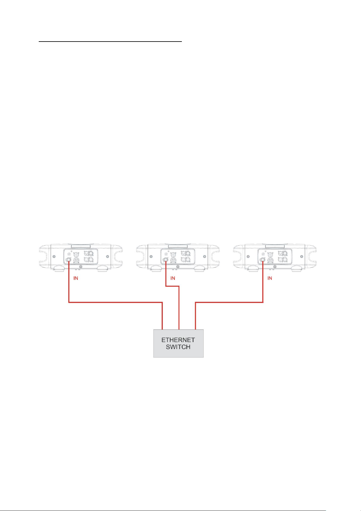
14- Art-Net / sACN SIGNAL CONNECTION
The unit operates using the Art-Net / sACN signal.
Connection between the mixer and the projector must be carried out using a category
5 network cable and a standard RJ45 connector.
14.1-Direct Ethernet operation
For direct Ethernet operation connect the mixer Art-Net / sACN signal via Ethernet
switch to each unit etherCON RJ45 input connector.
For each unit scroll till NETWORK menu (refer to DISPLAY FUNCTIONS for details):
• Select under INPUT menu “Art-Net” or “sACN” as input control signal.
• Select under IP ADDRESS MODE menu “Default” or “Static” mode.
• Select ETH TO DMX menu to OFF.
• Set the IP address and Net Mask. IP address must be different for each unit
on a network.
• Set the Art-Net or sACN Universe.
DMX address: 1 DMX address: 45 DMX address: 89
IP address: 002.214.192.007 IP address: 002.214.192.008 IP address: 002.214.192.009
Universe: 1 Universe: 1 Universe: 1
Page 19
19
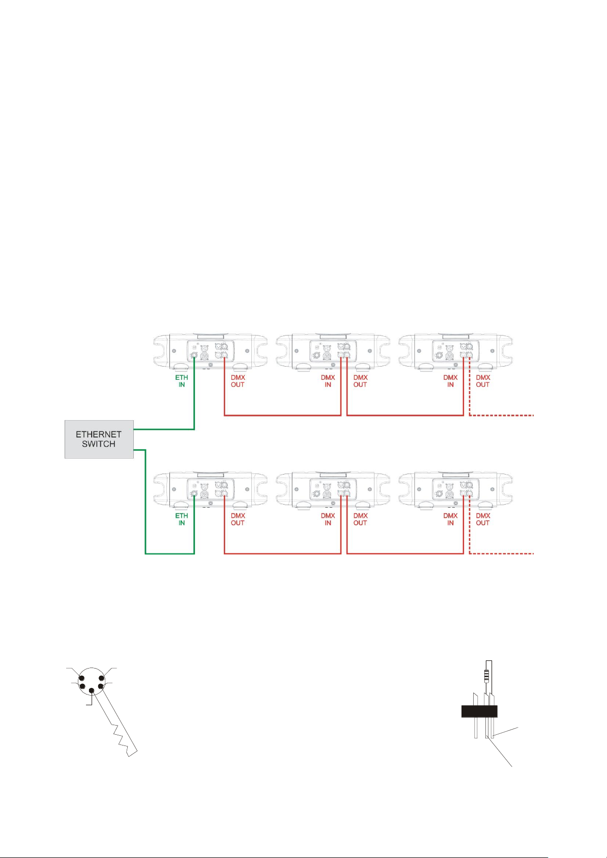
14.2-Ethernet to RDM/DMX operation
For Ethernet to RDM/DMX operation connect the mixer Art-Net / sACN signal via
Ethernet switch to the etherCON RJ45 input connector of the first unit only.
In this configuration the first unit works as an Ethernet to DMX converter and sends
RDM/DMX signal to its DMX output connector.
All the other units must be connected as a DMX chain with standard DMX settings.
Only for the first unit scroll till NETWORK menu (refer to DISPLAY FUNCTIONS for
details):
• Select under INPUT menu “Art-Net” or “sACN” as input control signal.
• Select under IP ADDRESS MODE menu “Default” or “Static” mode.
• Select ETH TO DMX menu to ON.
• Set the IP address and Net Mask. IP address must be different for each unit
on a network.
• Set the Art-Net or sACN Universe.
DMX address: 1 DMX address: 45 DMX address: 89
IP address: 002.214.192.007
Universe: 1
DMX address: 1 DMX address: 45 DMX address: 89
IP address: 002.214.192.008
Universe: 2
For Installations where long distance DMX cable connections are needed, we suggest
to use a DMX terminator.
The DMX terminator is a male XLR 3-5 pins connector with a 120 ohm resistor
between pin 2 and 3.
The DMX terminator must be plugged into the last unit (DMX out panel connector) of
the DMX line.
PLACE A 120 OHM RESISTOR BETWEEN PIN 2
AND 3 OF A MALE XRL CONNECTOR AND PLUG IT
INTO THE DMX OUT PANEL CONNECTOR OF THE
LAST UNIT CONNECTED TO THE DMX LINE
1
2
3
5
4
OUT
120 ohm
PIN 3
PIN 2
Page 20
20
15- RDM FUNCTIONS
By using a RDM controller it is possible to read / set DMX address, DMX mode and
other parameters. ALCHEMY 5 accepts the following RDM commands:
RDM Device Model ID: 0x0016
RDM PID DESCRIPTION
RDM PID VALUE
GET
SET
Category – Network Management
DISC_UNIQUE_BRANCH
0x0001
DISC_MUTE
0x0002
DISC_UN_MUTE
0x0003
Category – Status Collection
STATUS_MESSAGES
0x0030
X
STATUS_ID_DESCRIPTION
0x0031
X
Category - RDM Information
SUPPORTED_PARAMETERS
0x0050
X
PARAMETERS_DESCRIPTION
0x0051
X
Category – Product Information
DEVICE_INFO
0x0060
X
DEVICE_MODEL_DESCRIPTION
0x0080
X
MANUFACTURER_LABEL
0x0081
X
DEVICE_LABEL
0x0082
X
X
SOFTWARE_VERSION_LABEL
0x00C0
X
Category - DMX512 Setup
DMX_PERSONALITY
0x00E0
X
X
DMX_PERSONALITY_DESCRIPTION
0x00E1
X
DMX_START_ADDRESS
0x00F0
X
X
Category – Sensors
SENSOR_DEFINITION
0x0200
X
SENSOR_VALUE
0x0201
X
X
Category – Power/Lamp Settings
DEVICE_HOURS
0x0400
X
LAMP_HOURS
0x0401
X
Category – Display Settings
DISPLAY_INVERT
0x0500
X
X
Category – Configuration
PAN_INVERT
0x0600
X
X
TILT_INVERT
0x0601
X
X
Category – Control
IDENTIFY_DEVICE
0x1000
X
X
Category – Dimmer Settings
CURVE
0x0343
X
X
CURVE_DESCRIPTION
0x0344
X
OUTPUT_RESPONSE_TIME
0x0345
X
X
OUTPUT_RESPONSE_TIME_DESCRIPTION
0x0346
X
MODULATION_FREQUENCY
0x0347
X
X
MODULATION_FREQUENCY_DESCRIPTION
0x0348
X
Category – Custom PID
ETHERNET_TO_DMX
0x8000
X
X
INPUT_PRIORITY
0x8001
X
X
DISPLAY_STANDBY
0x8002
X
X
Page 21
21
15- RDM FUNCTIONS
RDM ADDITIONAL MESSAGEs:
CURVE
CURVE DESCRIPTION
1
LINEAR
2
QUADRATIC (default) 3
GAMMA 2.2
4
S-CURVE
OUTPUT RESPONSE TIME
OUTPUT_RESPONSE_TIME_DESCRIPTION
1
SMOOTH OFF
2
SMOOTH 1 ( 25 ms)
3
SMOOTH 2 ( 50 ms)
4
SMOOTH 3 ( 75 ms)
5
SMOOTH 4 (100 ms) (default)
6
SMOOTH 5 (125 ms)
7
SMOOTH 6 (150 ms)
8
SMOOTH 7 (175 ms)
9
SMOOTH 8 (200 ms)
10
SMOOTH 9 (225 ms)
11
SMOOTH 10 (250 ms)
12
SMOOTH 11 (275 ms)
13
SMOOTH 12 (300 ms)
14
SMOOTH 13 (325 ms)
15
SMOOTH 14 (350 ms)
16
SMOOTH 15 (375 ms)
17
SMOOTH 16 (400 ms)
18
SMOOTH 17 (425 ms)
19
SMOOTH 18 (450 ms)
20
SMOOTH 19 (475 ms)
21
SMOOTH 20 (500 ms)
Page 22
22
15- RDM FUNCTIONS
RDM ADDITIONAL MESSAGEs:
MODULATION FREQUENCY
MODULATION FREQUENCY DESCRIPTION
1
610 Hz
2
800 Hz
3
1.000 Hz (default)
4
1.500 Hz
5
2.000 Hz
6
2.500 Hz
7
3.000 Hz
8
3.500 Hz
9
4.000 Hz
10
4.500 Hz
11
5.000 Hz
RDM MANUFACTURER’S SPECIFIC PIDs:
RDM CUSTOM PID
DESCRIPTION
0x8000_ETHERNET_TO_DMX
Set parameter NETWORK – ETH TO DMX
0 = OFF (default)
1 = ON
0x8001_INPUT_PRIORITY
Set parameter NETWORK – PRIORITY
0 = DMX PORT (default)
1 = ETHERNET PORT
0x8002_DISPLAY_STANDBY
Set parameter DISPLAY – STANDBY
0 = DISABLED (default)
1 = ENABLED
2 = FORCED ENABLED
Page 23

23
15- RDM FUNCTIONS
RDM STATUS MESSAGE IDs:
Status Message ID
Data Value 1
Data Value 2
Status ID Description
0x8000
ERROR PAN MOTOR/ENCODER
0x8001
ERROR PAN LOCKED
0x8002
ERROR PAN ZERO SENSOR
0x8003
ERROR TILT MOTOR/ENCODER
0x8004
ERROR TILT LOCKED
0x8005
ERROR TILT ZERO SENSOR
0x8006
ERROR DMX ADDRESS
0x8007
ERROR PARAMETERS MEMORY
0x8008
ERROR SUPPLY VOLTS TOO LOW
0x8009
ERROR SUPPLY VOLTS TOO HIGH
0x800A
ERROR BUS ARTNET CARD
0x800B
ERROR BUS LED DRIVER CARD
0x800C
card number
ERROR BUS MOTORS CARD %d
0x8013
ERROR ZOOM
0x801B
ERROR EFFECTS
0x801C
prism number
ERROR PRISM %d
0x801D
prism number
ERROR PRISM %d INDEX
0x801F
ERROR TEMPERATURE LED MODULE
0x8020
sensor number
ERROR TEMPERATURE LED DRIVER %d
0x8021
ERROR TEMPERATURE MICRO
0x8022
ERROR RED
0x8023
ERROR GREEN
0x8024
ERROR BLUE
0x8025
ERROR AMBER
0x800E
ERROR CYAN
0x8026
ERROR LIME
16- FIRMWARE UPDATING
To update the firmware release of the ALCHEMY 5 you need:
- DTS Dongle Firmware Uploader (code 03.LA.206).
- “DTS Firmware Upgrade Utility v.2.02” program installed on PC.
- Latest firmware release available for ALCHEMY 5 unit.
Updating the firmware release.
Please follow the procedure below to perform the update:
1. Connect the DTS Dongle Firmware Uploader to a spare USB port on the PC.
2. Connect the unit DMX input to the DTS Dongle Firmware Uploader DMX output with
a standard DMX cable and turn ON the unit.
3. Send the new firmware release into the unit by using “DTS Firmware Upgrade
Utility v.2.02” program. At the end of the procedure, the unit will reset.
For more information please refer to an authorised DTS service centre.
Page 24

24
17- DISPLAY FUNCTIONS
The ALCHEMY 5 display panel shows all the available control menus.
Using these options, it is possible to change the fixture’s setting.
Changing the DTS settings can vary the functions of the unit so that it does not
respond to the DMX 512 used to control it. Carefully follow the instructions below
before carrying out any variations or selections.
MENU
• To access the control menus in the display panel.
• To return to the previous level in the menu structure without
making a change.
• To exit the menus.
ENTER
• To select any required menu.
• To confirm any changes.
UP / DOWN
• To navigate the menus structure.
• To change any value.
MOTORS FIRMWARE RELEASE
LED FIRMWARE RELEASE
12
1.00
RDM Device Model ID
0x0016
DMX Personality IDs
0x01 “CCT”
0x02 “ADVANCED”
0x03 “BASIC”
0x04 “EXPO”
Page 25

25
DISPLAY KEY-LOCK FUNCTION
Display key-lock function can be enabled/disabled by pressing ENTER + DOWN keys
at the same time for 3 seconds.
“ZERO SKIP” FUNCTION
“ZERO SKIP” function can be activated by pressing MENU + UP keys at the same
time during initial reset.
This function allows to have the display ON and all motors OFF.
Usefull when the unit is powered in the flight case and DMX address or other
parameters need to be set.
Page 26

26
MAIN MENU
LEVEL 1
LEVEL 2
LEVEL 3
FUNCTION
NETWORK
INPUT
DISABLED
Allows to disable
Ethernet operation.
(Default).
ARTNET
Allows to select Art-Net
as input control signal
protocol.
SACN
Allows to select sACN
as input control signal
protocol.
IP ADDR MODE
DEFAULT
Allows to select the
mode to set the IP
address and the Net
Mask.
Fixed IP address with
manual setting of
first byte only and
fixed Net Mask
(Default).
STATIC
Manual setting of IP
address and Net Mask.
DEFAULT IP
IP 2.214.192. 7
MASK 255. 0. 0. 0
Fixed IP address and
Net Mask.
It is possible to set only
first byte of the
IP address.
IP address must be
different for each
unit on a network.
ARTNET UNIV.
00000 - 32767
Allows to set the ArtNet Universe (range 0
÷ 32767).
SACN UNIVERSE
00001 - 63999
Allows to set the sACN
Universe (range 1 ÷
63999).
PRIORITY
DMX512
Allows to set the
priority between input
control signals when
the unit is connected
via DMX and via
ETHERNET at the
same time.
RDM/DMX signal has
the priority on the
Art-Net / sACN signal
(Default).
ETHERNET
Art-Net / sACN signal
has the priority on the
DMX signal.
ETH TO DMX
OFF
Allows to enable
ETHERNET to
RDM/DMX operation.
OFF = Default.
ON
In this configuration the
first unit works as an
Ethernet to DMX
converter and sends
RDM/DMX signal to its
DMX output connector.
NO SIGNAL
KEEP LAST
Allows to set the
desired unit’s behavior
in case Art-Net or
sACN signal is missing
or not available.
Keep last valid ArtNet or sACN signal
(Default).
BLACK OUT
Black-out.
Page 27

27
MAIN MENU
LEVEL 1
LEVEL 2
LEVEL 3
FUNCTION
PAN DIRECTION
NORMAL
Allows to set the Pan
movement.
Normal or Reverse.
Normal (Default).
REVERSE
TILT DIRECTION
NORMAL
Allows to set the Tilt
movement.
Normal or Reverse.
Normal (Default).
REVERSE
ZOOM
DIRECTION
NORMAL
Allows to set the Zoom
movement.
Normal or Reverse.
Normal (Default).
REVERSE
OPERATING
MODE
SILENT
Reduced Pan-TiltZoom-Fans speed for
low noise operation
(Default).
STANDARD
Pan-Tilt-Zoom-Fans
standard speed.
FAN MODE
(FAN MODE will work
relatively to
OPERATING MODE)
CONSTANT
Same fans speed in
any working
condition in SILENT
or STANDARD
operating mode
(Default).
AUTOMATIC
Automatic fans speed.
If LED temperature
<40°C: fans OFF.
If LED temperature
>40°C:
If OPERATING MODE
= SILENT, fans speed
is increased within the
values range set in
SILENT mode.
If OPERATING MODE
= STANDARD, fans
speed is increased
within the values range
set in STANDARD
mode.
DISPLAY
FLIP
AUTO
Reverses display’s
reading depending on
the mounting position.
Automatic, on the
ground or suspended.
Automatic (Default).
ON THE
GROUND
SUSPENDED
STANDBY
DISABLED
Display stand-by
disabled (Default).
ENABLED
Display goes OFF after
5 seconds.
FORCED EN.
Display forced OFF
even if control signal is
missing or error
messages are shown.
CONTRAST
20 - 35
Display contrast
regulation.
Range 20-35.
Default = 25.
DMX MODE
Personality
CCT
20 channels
Allows to select CCT
mode (20 DMX
channels). Default.
ADVANCED
28 channels
Allows to select
ADVANCED mode (28
DMX channels).
BASIC
23 channels
Allows to select BASIC
mode (23 DMX
channels).
EXPO
13 channels
Allows to select EXPO
mode (13 DMX
channels).
Page 28

28
MAIN MENU
LEVEL 1
LEVEL 2
LEVEL 3
FUNCTION
NO DMX
ACTION
KEEP LAST DMX
Allows to set the
desired unit’s behavior
in case DMX signal is
missing or not
available.
Keep last valid DMX
signal (Default).
PROGRAM 1-48
1 - 48
48 pre-programmed
steps. Speed time
values (range 0.5x –
3x) selectable by user
(default 1x).
SINGLE CUE
PAN MSB
0 - 255
Fixed cue with values
selectable by user.
Default = 128
PAN LSB
0 - 255
Default = 128
TILT MSB
0 - 255
Default = 128
TILT LSB
0 - 255
Default = 128
SPEED
MOVEMENT
0 - 255
Default = 0
SHUTTER
0 - 255
Default = 15
DIMMER MSB
0 - 255
Default = 255
DIMMER LSB
0 - 255
Default = 255
CCT
0 - 255
Default = 0
GEL LIBRARY
0 - 255
Default = 0
RED
0 - 255
Default = 255
GREEN
0 - 255
Default = 255
BLUE
0 - 255
Default = 255
AMBER
0 - 255
Default = 255
CYAN
0 - 255
Default = 255
LIME
0 - 255
Default = 255
FROST/COL.
0 - 255
Default = 0
BEAM SHAPER
0 - 255
Default = 0
BEAM SHP R-I
0 - 255
Default = 0
ZOOM
0 - 255
Default = 128
BLACKOUT
Black-out.
RESET BY DMX
ENABLED
Reset via DMX
enabled (Default).
DISABLED
Reset via DMX
disabled.
NOW
Instant unit motors
reset.
LED
SMOOTH
OFF - 20
Allows to select the
value of delay (in ms)
for DIMMER channel
reaction to DMX
dimming command.
OFF = Instant
response.
4 = 100 ms smooth
response (Default).
20 = 500 ms smooth
response.
Page 29

29
MAIN MENU
LEVEL 1
LEVEL 2
LEVEL 3
FUNCTION
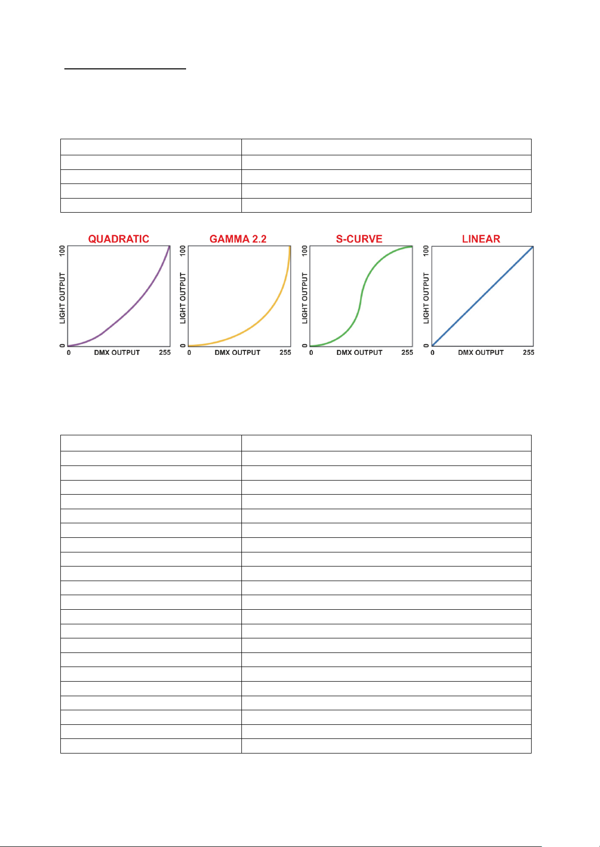
LED
GAMMA CORR.
QUAD
Allows to set
quadratic current
output for LED
(Default).
2.2
Allows to set gamma
curve 2.2 .
S-CURVE
Allows to set S-curve
to emulates light
intensity characteristics
of the tungsten
halogen lamps.
LINE
Allows to set linear
light output.
FREQUENCY
610 - 5000 HZ
Allows to adjust the
PWM frequency value
(Hz) in order to reduce
flickering in the
process of your
camera recordings.
Range = 610 Hz – 5
KHz
Default = 1000 Hz
TUNGSTEN
EMU.
DISABLED
Allows to enable
Tungsten Emulation.
Variation in the dimmer
intensity will affect
CCT values.
Disabled (Default).
Not yet implemented.
ENABLED
CROSSFADE
INTERMEDIATE
Allows to set
Crossfade
Intermediate for
‘CCT/GEL FADE TO
RGBACL’ channel 15
of “ADVANCED”
DMX mode (Default).
TRANSITION
Allows to set
Crossfade Transition
for ‘CCT/GEL FADE
TO RGBACL’ channel
15 of “ADVANCED”
DMX mode.
“GAMMA CORR.” GRAPHICS:
“CROSSFADE” GRAPHICS:
Page 30

30
MAIN MENU
LEVEL 1
LEVEL 2
LEVEL 3
FUNCTION
SYSTEM INFO
SOFTWARE
ALCHEMY 5
29 MAY 2019
MOTOR: V.01
LED:V.1.00
Unit model, motors
firmware release date,
Motors board and LED
Driver board firmware
release.
TEMPERATURES
LED: 041°C
DRV-1: 043°C
DRV-2: 044°C
MICRO: 040°C
LED: LED temperature
monitoring.
DRV-1: output 1 and
output 2 of LED Driver
board temperature
monitoring.
DRV-2: output 3 and
output 4 of LED Driver
board temperature
monitoring.
MICRO: Micro
controller temperature
monitoring.
TIME COUNTERS
UNIT: 0082H
DRIVER: 0080H
RED: 0045H
GREEN: 0068H
BLUE: 0023H
AMBER: 0037H
CYAN: 0067H
LIME: 0058H
Unit, LED Driver board
and LED channels life
time.
ADDRESSES
RDM:
0710:000113F1
MAC:
70:B3:D5:D7:C3:A3
RDM and MAC IDs.
RESERVED
ENTER CODE
0 – 255
(code 100)
PAN LOCK
NO
Lock the Pan to the
desired value.
NO = Default.
YES
TILT LOCK
NO
Lock the Tilt to the
desired value.
NO = Default.
YES
PAN FREE
NO
Remove power to Pan
motor.
NO = Default.
YES
TILT FREE
NO
Remove power to Tilt
motor.
NO = Default.
YES
LOCK DETECTOR
ON
Allows to activate the
Lock detector on Pan
and Tilt.
If for any reason there
is something blocking
the movement for
Pan&Tilt motors during
the initial reset
(example unit into the
flight case and power
connected), it
automatically will stop
to reset Pan&Tilt
motors after 5 seconds
from the startup and a
warning message
(Pan locked-Tilt
locked) will appear on
unit display.
ON = Default.
OFF
REBOOT
Unit reboot without
needing of turning
OFF the unit.
EXIT TO MAIN
Exit from Reserved
menu.
Page 31

31
MAIN MENU
LEVEL 1
LEVEL 2
LEVEL 3
FUNCTION
DEFAULT
To restore factory
settings.
MANUAL
CONTR.
RESET
HEAD MOTORS
To reset head motors
only.
PAN TILT
To reset Pan and Tilt
only.
ALL MOTORS
To reset all motors.
RESTORE DEF.
To restore parameters
default settings.
PAN MSB
0 - 255
Manual mode with
functions value
selectable by user.
Default = 128
PAN LSB
0 - 255
Default = 128
TILT MSB
0 - 255
Default = 128
TILT LSB
0 - 255
Default = 128
SPEED
MOVEMENT
0 - 255
Default = 0
SHUTTER
0 - 255
Default = 15
DIMMER MSB
0 - 255
Default = 255
DIMMER LSB
0 - 255
Default = 255
CCT
0 - 255
Default = 0
GEL LIBRARY
0 - 255
Default = 0
RED
0 - 255
Default = 255
GREEN
0 - 255
Default = 255
BLUE
0 - 255
Default = 255
AMBER
0 - 255
Default = 255
CYAN
0 - 255
Default = 255
LIME
0 - 255
Default = 255
FROST/COL.
0 - 255
Default = 0
BEAM SHAPER
0 - 255
Default = 0
BEAM SHP R-I
0 - 255
Default = 0
ZOOM
0 - 255
Default = 128
Page 32

32
18- ERROR MESSAGES
ERROR SHOWN ON DISPLAY
APPEARS WHEN
PAN
-Pan motor fault
-Pan encoder fault
-Pan motor driver on Pan&Tilt PCB fault
-Wiring connection between Pan encoder and
Pan&Tilt PCB fault
PAN LOCKED
-Pan locked
-Pan motor fault
-Pan encoder fault
-Pan motor driver on Pan&Tilt PCB fault
-Wiring connection between Pan encoder and
Pan&Tilt PCB fault
TILT
-Tilt motor fault
-Tilt encoder fault
-Tilt motor driver on Pan&Tilt PCB fault
-Wiring connection between Tilt encoder and
Pan&Tilt PCB fault
TILT LOCKED
-Tilt locked
-Tilt motor fault
-Tilt encoder fault
-Tilt motor driver on Pan&Tilt PCB fault
-Wiring connection between Tilt encoder and
Pan&Tilt PCB fault
PAN ZERO SENSOR LINE
-Pan magnet missing
-Pan hall sensor PCB fault
-Wiring connection between Pan hall sensor PCB
and Pan&Tilt PCB fault
TILT ZERO SENSOR LINE
-Tilt magnet missing
-Tilt hall sensor PCB fault
-Wiring connection between Tilt hall sensor PCB
and Pan&Tilt PCB fault
TEMP. LED MOD.
LED module temperature detected under -10°C or
over 80°C.
Unit immediately goes in black-out.
TEMP. LED DRV 1
Output from 1 to 4 of LED Driver PCB temperature
detected under -10°C or over 90°C.
Unit immediately goes in black-out.
TEMP. LED DRV 2
Output from 5 to 8 of LED Driver PCB temperature
detected under -10°C or over 90°C.
Unit immediately goes in black-out.
TEMP. LED MICRO
Micro controller on LED Driver PCB temperature
detected under -10°C or over 80°C.
Unit immediately goes in black-out.
R/G/B/A/C/L OPEN
(not yet implemented)
LED channel in open circuit.
Unit immediately goes in black-out.
R/G/B/A/C/L SHORT
(not yet implemented)
LED channel in short circuit.
Unit immediately goes in black-out.
SUPPLY VOLTS TOO LOW
PCBs input voltage <46,5Vdc.
SUPPLY VOLTS TOO HIGH
PCBs input voltage >49,5Vdc.
Page 33

33
18- ERROR MESSAGES
ERROR SHOWN ON DISPLAY
APPEARS WHEN
BUS 5 MOTORS CARD
-Pan&Tilt PCB driver fault
-5 Motors PCB driver fault
-5 Motors PCB input voltage missing
-Internal Bus wiring connection fault
BUS LED DRIVER CARD
-Pan&Tilt PCB driver fault
-LED Driver PCB driver fault
-LED Driver PCB input voltage missing
-Internal Bus wiring connection fault
BUS ARTNET CARD
-Pan&Tilt PCB driver fault
-Art-Net PCB driver fault
-Art-Net PCB input voltage missing
-Wiring connection between Art-Net PCB and
Pan&Tilt PCB fault
ZOOM DX
OR RESET LINE 4
-Zoom DX motor fault
-Zoom DX motor driver on 5 Motors PCB fault
-Zoom DX magnet missing
-Zoom DX hall sensor PCB fault
ZOOM SX
OR RESET LINE 3
-Zoom SX motor fault
-Zoom SX motor driver on 5 Motors PCB fault
-Zoom SX magnet missing
-Zoom SX hall sensor PCB fault
EFFECTS
OR RESET LINE 2
-Effects wheel motor fault
-Effects wheel motor driver on 5 Motors PCB fault
-Effects wheel magnet missing
-Effects wheel hall sensor PCB fault
PRISM
OR RESET LINE 1
-Prism motor fault
-Prism motor driver on 5 Motors PCB fault
-Prism magnet missing
-Prism hall sensor PCB fault
PRISM INDEX
OR RESET LINE 5
-Prism Index motor fault
-Prism Index motor driver on 5 Motors PCB fault
-Prism Index magnet missing
-Prism Index hall sensor PCB fault
Page 34

34
19- PERIODIC CLEANING
19.1- Lenses and reflectors
Even a fine layer of dust can reduce the luminous output substantially.
Regularly clean all lenses and the reflector using a soft cotton cloth, dampened with a
specialist lens cleaning solution.
19.2- Fans and air passages
The fans and air passages must be cleaned approximately every 6 weeks.
This periodic cleaning will depend of course, on the conditions in which the projector is
operating.
Suitable instruments for performing this type of maintenance are a brush and a
common vacuum cleaner or an air compressor.
If necessary, clean the fans and air passages more frequently.
20- PERIODIC CONTROLS
Attention
Disconnect mains power prior to opening the projector housing.
Mechanical parts
Periodically check all mechanical parts, gears, guides, belts, etc. for wear and tear,
replacing them if necessary.
Periodically check the lubrification of all components, particularly the parts subject to
high temperatures.
If necessary, lubrificate with suitable lubrificant, available from your DTS distributor.
Check the tension of the belts and adjust it if necessary.
Electrical components
Check all electrical components for correct earthing and proper connection of all
connectors, refastening if necessary.
Fuse replacement
Locate the fuse, which protects the lamp and electronics, in the base of ALCHEMY 5.
Using a multimeter, test the condition of the fuse, replacing it with one of equivalent
type (T 8A 250V) if necessary.
!
Page 35

35
21- DMX PROTOCOL
1. “CCT” mode (20 DMX channels) (Default)
1 PAN msb
2 PAN lsb
3 TILT msb
4 TILT lsb
5 SPEED MOVEMENT
6 SHUTTER
7 DIMMER msb
8 DIMMER lsb
9 CCT (1.800K – 10.000K)
10 GREEN SATURATION
11 GEL LIBRARY 1
12 GELS X-FADE
13 GEL LIBRARY 2
14 GEL FILTER DESATURATION
15 FROST/COLOUR WHEEL
16 BEAM SHAPER
17 BEAM SHAPER INDEX/ROTATION
18 ZOOM
19 FIXTURE CONTROL
20 RESET
DMX CHANNEL
1
Parameter: PAN msb
DMX CHANNEL
2
Parameter: PAN lsb
DMX CHANNEL
3
Parameter: TILT msb
DMX CHANNEL
4
Parameter: TILT lsb
DMX CHANNEL
5
Parameter: SPEED MOVEMENT
DMX value
Function
000-009
Fast movement
010-025
Standard movement
026-127
Vector mode from fast to slow
128-247
Variable time reaction to dmx signal (fast to slow)
248-250
Silent movement
251-255
Snap movement
Page 36

36
DMX CHANNEL
6
Parameter: SHUTTER
DMX value
Function
000-009
Black Out
010-019
Open
020-029
Black Out
030-119
Strobe (from 3,27s to 30ms)
120-149
Pulse up (from 42,6s to 120ms)
150-179
Pulse down (from 42,6s to 120ms)
180-189
Random strobe
190-199
Open
200-209
Effect wheel in Black Out while rotating
210-219
Pan/Tilt in Black Out while moving
220-222
Open
223-224
Beam shaper in Black Out while inserting
225-226
Zoom in Black Out while moving
227-229
Effect wheel/Beam Shaper/Zoom in Black Out while moving
230-255
Open
DMX CHANNEL
7
Parameter: DIMMER msb
DMX CHANNEL
8
Parameter: DIMMER lsb
DMX CHANNEL
9
Parameter: CCT
DMX value
Function
000-255
Correlate colour temperature from 1800K to 10000K.
Relevant CCT values (GREEN SATURATION channel 10 @ 128)
1800K = 000
2700K = 070
3000K = 083
3200K = 092
4000K = 119
5000K = 148
5600K = 163
6000K = 174
6500K = 184
7000K = 195
8000K = 215
9000K = 233
10000K = 255
DMX CHANNEL
10
Parameter: GREEN SATURATION
DMX value
Function
000-127
From full minus green to neutral
128
Neutral (Default)
129-255
From neutral to full plus green
Page 37

37
DMX CHANNEL
11
Parameter: GEL LIBRARY 1
DMX value
Function
000-009
No function
010-011
M001: L 002 Rose Pink
012-013
M002: L 007 Pale Yellow
014-015
M003: L 015 Deep Straw
016-017
M004: L 019 fire
018-019
M005: L 020 medium amber
020-021
M006: L 021 Gold Amber
022-023
M007: L 022 Dark Amber
024-025
M008: L 025 sunset red
026-027
M009: L 046 Dark Magenta
028-029
M010: L 049 Medium Purple
030-031
M011: L 058 Lavender
032-033
M012: L 068 Sky Blue
034-035
M013: L 079 Just Blue
036-037
M014: L 085 Deeper Blue
038-039
M015: L 088 Lime Green
040-041
M016: L 089 moss green
042-043
M017: L 100 Spring Yellow
044-045
M018: L 101 yellow
046-047
M019: L 102 light amber
048-049
M020: L 103 Straw
050-051
M021: L 104 DEEP AMBER
052-053
M022: L 105 Orange
054-055
M023: L 106 primary red
056-057
M024: L 108 English rose
058-059
M025: L 111 dark pink
060-061
M026: L 113 magenta
062-063
M027: L 115 peacock blue
064-065
M028: L 117 Steel Blue
066-067
M029: L 118 LIGHT BLU
068-069
M030: L 119 dark blue
070-071
M031: L 121 lee green
072-073
M032: L 122 fern green
074-075
M033: L 124 dark green
076-077
M034: L 126 mauve
078-079
M035: L 132 Medium Blue
080-081
M036: L 136 Pale Lavender
082-083
M037: L 137 Special lavender
084-085
M038: L 138 Pale Green
086-087
M039: L 139 primary green
088-089
M040: L 142 Pale Violet
090-091
M041: L 147 apricot
092-093
M042: L 151 Gold Tint
094-095
M043: L 152 pale gold
096-097
M044: L 154 pale rose
098-099
M045: L 156 Chocolate
100-101
M046: L 164 flame red
102-103
M047: L 170 deep lavender
104-105
M048: L 174 dark steel blue
106-107
M049: L 176 loving amber
108-109
M050: L 179 chrome orange
110-111
M051: L 180 dark lavender
112-113
M052: L 181 congo blue
Page 38

38
DMX CHANNEL
11
Parameter: GEL LIBRARY 1
DMX value
Function
114-115
M053: L 182 Light Red
116-117
M054: L 194 Surprise Pink
118-119
M055: L 195 zenith blue
120-121
M056: L 200 Double C.T. Blue
122-123
M057: L 201 Full C.T. Blue
124-125
M058: L 202 Half C.T Blue
126-127
M059: L 203 Quarter C.T. Blue
128-129
M060: L 204 Full C.T. Orange
130-131
M061: L 205 Half C.T. Orange
132-133
M062: L 206 Quarter C.T. Orange
134-135
M063: L 242 Fluorescent 4300 Kevin
136-137
M064: L 249 1/4 minus green
138-139
M065: L 323 jade
140-141
M066: L 328 Follies Pink
142-143
M067: L 343 special medium lavender
144-145
M068: L 345 fuchsia pink
146-147
M069: L 341 Plum
148-149
M070: L 353 lighter blue
150-151
M071: L 506 Marlene
152-153
M072: L 601 Silver
154-155
M073: L 725 Old Steel Blue
156-157
M074: L 728 Steel Green
158-159
M075: L 731 Dirty Ice
160-161
M076: L 765 LEE Yellow
162-163
M077: L 777 rust
164-165
M078: L 795 Magical Magenta
166-167
M079: L 797 Deep Purple
168-169
M080: R 03 Dark Bastard Amber
170-171
M081: R 05 Rose tint
172-173
M082: R 11 Light Straw
174-175
M083: R 23 Orange
176-177
M084: R 25 Orange Red
178-179
M085: R 31 Salmon Pink
180-181
M086: R 35 Light pink
182-183
M087: R 40 Light Salmon
184-185
M088: R 54 special lavender
186-187
M089: R 57 Lavender
188-189
M090: R 61 Mist Blue
190-191
M091: R 68 Parry Sky Blue
192-193
M092: R 75 Twilight Blue
194-195
M093: R 79 Bright Blue
196-197
M094: R 82 Surprise Blue
198-199
M095: R 89 Moss Green
200-201
M096: R 303 Warm Peach
202-203
M097: R 318 Mayan Sun
204-205
M098: R 363 Aquamarine
206-207
M099: R 385 Royal Blue
208-209
M100: R 386 Leaf Green
210-255
No function
DMX CHANNEL
12
Parameter: GEL X-FADE
DMX value
Function
000-255
Crossfade between GEL LIBRARY 1 and GEL LIBRARY 2
0 = 100% GEL LIBRARY 1, 0% GEL LIBRARY 2
128 = 50% GEL LIBRARY 1, 50% GEL LIBRARY 2
255 = 0% GEL LIBRARY 1, 100% GEL LIBRARY 2
Page 39

39
DMX CHANNEL
13
Parameter: GEL LIBRARY 2
DMX value
Function
000-009
No function
010-011
M001: L 002 Rose Pink
012-013
M002: L 007 Pale Yellow
014-015
M003: L 015 Deep Straw
016-017
M004: L 019 fire
018-019
M005: L 020 medium amber
020-021
M006: L 021 Gold Amber
022-023
M007: L 022 Dark Amber
024-025
M008: L 025 sunset red
026-027
M009: L 046 Dark Magenta
028-029
M010: L 049 Medium Purple
030-031
M011: L 058 Lavender
032-033
M012: L 068 Sky Blue
034-035
M013: L 079 Just Blue
036-037
M014: L 085 Deeper Blue
038-039
M015: L 088 Lime Green
040-041
M016: L 089 moss green
042-043
M017: L 100 Spring Yellow
044-045
M018: L 101 yellow
046-047
M019: L 102 light amber
048-049
M020: L 103 Straw
050-051
M021: L 104 DEEP AMBER
052-053
M022: L 105 Orange
054-055
M023: L 106 primary red
056-057
M024: L 108 English rose
058-059
M025: L 111 dark pink
060-061
M026: L 113 magenta
062-063
M027: L 115 peacock blue
064-065
M028: L 117 Steel Blue
066-067
M029: L 118 LIGHT BLU
068-069
M030: L 119 dark blue
070-071
M031: L 121 lee green
072-073
M032: L 122 fern green
074-075
M033: L 124 dark green
076-077
M034: L 126 mauve
078-079
M035: L 132 Medium Blue
080-081
M036: L 136 Pale Lavender
082-083
M037: L 137 Special lavender
084-085
M038: L 138 Pale Green
086-087
M039: L 139 primary green
088-089
M040: L 142 Pale Violet
090-091
M041: L 147 apricot
092-093
M042: L 151 Gold Tint
094-095
M043: L 152 pale gold
096-097
M044: L 154 pale rose
098-099
M045: L 156 Chocolate
100-101
M046: L 164 flame red
102-103
M047: L 170 deep lavender
104-105
M048: L 174 dark steel blue
106-107
M049: L 176 loving amber
108-109
M050: L 179 chrome orange
110-111
M051: L 180 dark lavender
112-113
M052: L 181 congo blue
Page 40

40
DMX CHANNEL
13
Parameter: GEL LIBRARY 2
DMX value
Function
114-115
M053: L 182 Light Red
116-117
M054: L 194 Surprise Pink
118-119
M055: L 195 zenith blue
120-121
M056: L 200 Double C.T. Blue
122-123
M057: L 201 Full C.T. Blue
124-125
M058: L 202 Half C.T Blue
126-127
M059: L 203 Quarter C.T. Blue
128-129
M060: L 204 Full C.T. Orange
130-131
M061: L 205 Half C.T. Orange
132-133
M062: L 206 Quarter C.T. Orange
134-135
M063: L 242 Fluorescent 4300 Kevin
136-137
M064: L 249 1/4 minus green
138-139
M065: L 323 jade
140-141
M066: L 328 Follies Pink
142-143
M067: L 343 special medium lavender
144-145
M068: L 345 fuchsia pink
146-147
M069: L 341 Plum
148-149
M070: L 353 lighter blue
150-151
M071: L 506 Marlene
152-153
M072: L 601 Silver
154-155
M073: L 725 Old Steel Blue
156-157
M074: L 728 Steel Green
158-159
M075: L 731 Dirty Ice
160-161
M076: L 765 LEE Yellow
162-163
M077: L 777 rust
164-165
M078: L 795 Magical Magenta
166-167
M079: L 797 Deep Purple
168-169
M080: R 03 Dark Bastard Amber
170-171
M081: R 05 Rose tint
172-173
M082: R 11 Light Straw
174-175
M083: R 23 Orange
176-177
M084: R 25 Orange Red
178-179
M085: R 31 Salmon Pink
180-181
M086: R 35 Light pink
182-183
M087: R 40 Light Salmon
184-185
M088: R 54 special lavender
186-187
M089: R 57 Lavender
188-189
M090: R 61 Mist Blue
190-191
M091: R 68 Parry Sky Blue
192-193
M092: R 75 Twilight Blue
194-195
M093: R 79 Bright Blue
196-197
M094: R 82 Surprise Blue
198-199
M095: R 89 Moss Green
200-201
M096: R 303 Warm Peach
202-203
M097: R 318 Mayan Sun
204-205
M098: R 363 Aquamarine
206-207
M099: R 385 Royal Blue
208-209
M100: R 386 Leaf Green
210-255
No function
Page 41

41
DMX CHANNEL
14
Parameter: GEL FILTER DESATURATION
DMX value
Function
000-255
Gel filters desaturation
0 = 100% color
255 = 0% color
DMX CHANNEL
15
Parameter: FROST/COLOUR WHEEL
DMX value
Function
000-009
No Function
010-050
Light frost
051-090
Heavy frost
091-130
Deep blue filter switch ON (BLUE channel forced at full)
131-170
Deep red filter switch ON (RED channel forced at full)
171-210
Deep blue filter manual control
211-255
Deep red filter manual control
DMX CHANNEL
16
Parameter: BEAM SHAPER
DMX value
Function
000-009
No Function
010-255
Beam shaper inserted
DMX CHANNEL
17
Parameter: BEAM SHAPER INDEX/ROTATION
DMX value
Function
000-009
No Function
010-127
Proportional index 0°-360°
128-180
CW rotation from fast to slow
181-202
Stop
203-255
CCW rotation from slow to fast
DMX CHANNEL
18
Parameter: ZOOM
DMX value
Function
000-255
Linear zoom from min to max
Page 42

42
DMX CHANNEL
19
Parameter: FIXTURE CONTROL
Function
000-009
0 - No effect
010-024
1 – SMOOTH DIMMING OFF
025-026
2 - SMOOTH DIMMING 1
027-028
3 - SMOOTH DIMMING 2
029-030
4 - SMOOTH DIMMING 3
031-032
5 - SMOOTH DIMMING 4 (Default)
033-034
6 - SMOOTH DIMMING 5
035-036
7 - SMOOTH DIMMING 6
037-038
8 - SMOOTH DIMMING 7
039-040
9 - SMOOTH DIMMING 8
041-042
10 - SMOOTH DIMMING 9
043-044
11 - SMOOTH DIMMING 10
045-046
12 - SMOOTH DIMMING 11
047-048
13 - SMOOTH DIMMING 12
049-050
14 - SMOOTH DIMMING 13
051-052
15 - SMOOTH DIMMING 14
053-054
16 - SMOOTH DIMMING 15
055-056
17 - SMOOTH DIMMING 16
057-058
18 - SMOOTH DIMMING 17
059-060
19 - SMOOTH DIMMING 18
061-062
20 - SMOOTH DIMMING 19
063-064
21 - SMOOTH DIMMING 20
065-066
22 - GAMMA CORRECTION QUADRATIC (Default)
067-068
23 - GAMMA CORRECTION LINEAR
069-070
24 - GAMMA CORRECTION S-CURVE
071-072
25 - GAMMA CORRECTION 2.2
073-074
26 - reserved
075-076
27 – TUNGSTEN EMULATION DISABLED (Default) (to be defined)
077-078
28 – TUNGSTEN EMULATION ENABLED (to be defined)
079-080
29 – CROSSFADE CURVE INTERMEDIATE (Default)
081-082
30 – CROSSFADE CURVE TRANSITION
083-084
31 – reserved
085-104
32 - OUTPUT FREQUENCY 610 Hz
105
33 - OUTPUT FREQUENCY 800 Hz
106
34 - OUTPUT FREQUENCY 1000 Hz (Default)
107
35 - OUTPUT FREQUENCY 1500 Hz
108
36 - OUTPUT FREQUENCY 2000 Hz
109
37 - OUTPUT FREQUENCY 2500 Hz
110
38 - OUTPUT FREQUENCY 3000 Hz
111
39 - OUTPUT FREQUENCY 3500 Hz
112
40 - OUTPUT FREQUENCY 4000 Hz
113
41 - OUTPUT FREQUENCY 4500 Hz
114
42 - OUTPUT FREQUENCY 5000 Hz
115
43 - reserved
116
44 - reserved
117
45 - reserved
118
46 - reserved
119
47 - reserved
120
48 - reserved
121
49 - reserved
122
50 - reserved
123
51 - reserved
Page 43

43
DMX CHANNEL
19
Parameter: FIXTURE CONTROL
Function
124
52 - reserved
125
53 - reserved
126
54 - reserved
127
55 - reserved
128
56 - reserved
129
57 - reserved
130
58 - reserved
131
59 - reserved
132
60 - reserved
133
61 - reserved
134
62 - reserved
135-136
63 - reserved
137-138
64 - reserved
139-140
65 - reserved
141-142
66 - reserved
143-144
67 - reserved
145-146
68 - reserved
147-148
69 - reserved
149-150
70 - reserved
151-152
71 – reserved
153-154
72 – reserved
155-156
73 - DISPLAY STANDBY DISABLED (Default)
157-158
74 - DISPLAY STANDBY ENABLED
159-160
75 - DISPLAY STANDBY FORCED ENABLED
161-174
76 – reserved
175-176
77 - NO DMX ACTION – KEEP LAST DMX (Default)
177-178
78 - NO DMX ACTION – BLACK OUT
179-180
79 - reserved
181-182
80 - NO DMX ACTION – DEMO PROGRAM (STEPS 01..48)
183-184
81 - NO DMX ACTION – SINGLE CUE
185-186
82 - PAN NORMAL (Default)
187-188
83 - PAN REVERSE
189-190
84 - reserved
191-192
85 - reserved
193-194
86 - reserved
195-196
87 - reserved
197-198
88 - TILT NORMAL (Default)
199-200
89 - TILT REVERSE
201-202
90 - reserved
203-204
91 - reserved
205-206
92 - reserved
207-208
93 - reserved
209-210
94 – ZOOM NORMAL (Default)
211-212
95 - ZOOM REVERSE
213-214
96 - reserved
215-216
97 - reserved
217-218
98 - reserved
219-220
99 - reserved
221-222
100 - reserved
223-224
101 - reserved
225-226
102 - reserved
227-228
103 - reserved
229-230
104 - reserved
231-232
105 - reserved
233-234
106 - reserved
Page 44

44
DMX CHANNEL
19
Parameter: FIXTURE CONTROL
Function
235-236
107 – OPERATING MODE SILENT (Default)
237-238
108 - OPERATING MODE STANDARD
239-240
109 – reserved
241-242
110 – FAN MODE CONSTANT (Default)
243-244
111 – FAN MODE AUTO
245-246
112 – reserved
247-248
113 – reserved
249-250
114 – reserved
251-252
115 – reserved
253-255
116 - SET FUNCTION TO DEFAULT:
-SMOOTH DIMMING = 4
-GAMMA = QUADRATIC
-FREQUENCY = 1000 Hz
-DISPLAY STANDBY = DISABLE
-NO DMX ACTION = KEEP LAST DMX
-OPERATING MODE = SILENT
-FAN MODE = CONSTANT
-PAN DIRECTION = NORMAL
-TILT DIRECTION = NORMAL
-ZOOM DIRECTION = NORMAL
-TUNGSTEN EMULATION = DISABLED
-CROSSFADE CURVE = INTERMEDIATE
DMX CHANNEL
20
Parameter: RESET
DMX value
Function
000-009
No effect
010-075
PAN TILT reset
076-095
HEAD MOTORS reset
096-115
reserved
116-135
Effects wheel reset
136-155
reserved
156-175
reserved
176-195
BEAM SHAPER reset
196-215
reserved
216-239
ZOOM reset
240-255
Total unit reset (PAN TILT + HEAD MOTORS)
Page 45

45
2. “ADVANCED” mode (28 DMX channels)
78 PAN msb
2 PAN lsb
3 TILT msb
4 TILT lsb
5 SPEED MOVEMENT
6 SHUTTER
7 DIMMER msb
8 DIMMER lsb
9 CCT (1.800K – 10.000K)
10 GREEN SATURATION
11 GEL LIBRARY 1
12 GELS X-FADE
13 GEL LIBRARY 2
14 GEL FILTER DESATURATION
15 CCT/GEL FADE TO RGBACL
16 RED
17 GREEN
18 BLUE
19 AMBER
20 CYAN
21 LIME
22 FROST/COLOUR WHEEL
23 BEAM SHAPER
24 BEAM SHAPER INDEX/ROTATION
25 reserved
26 ZOOM
27 FIXTURE CONTROL
28 RESET
DMX CHANNEL
1
Parameter: PAN msb
DMX CHANNEL
2
Parameter: PAN lsb
DMX CHANNEL
3
Parameter: TILT msb
DMX CHANNEL
4
Parameter: TILT lsb
DMX CHANNEL
5
Parameter: SPEED MOVEMENT
DMX value
Function
000-009
Fast movement
010-025
Standard movement
026-127
Vector mode from fast to slow
128-247
Variable time reaction to dmx signal (fast to slow)
248-250
Silent movement
251-255
Snap movement
Page 46

46
DMX CHANNEL
6
Parameter: SHUTTER
DMX value
Function
000-009
Black Out
010-019
Open
020-029
Black Out
030-119
Strobe (from 3,27s to 30ms)
120-149
Pulse up (from 42,6s to 120ms)
150-179
Pulse down (from 42,6s to 120ms)
180-189
Random strobe
190-199
Open
200-209
Effect wheel in Black Out while rotating
210-219
Pan/Tilt in Black Out while moving
220-222
Open
223-224
Beam shaper in Black Out while inserting
225-226
Zoom in Black Out while moving
227-229
Effect wheel/Beam Shaper/Zoom in Black Out while moving
230-255
Open
DMX CHANNEL
7
Parameter: DIMMER msb
DMX CHANNEL
8
Parameter: DIMMER lsb
DMX CHANNEL
9
Parameter: CCT
DMX value
Function
000-255
Correlate colour temperature from 1800K to 10000K.
Relevant CCT values (GREEN SATURATION channel 10 @ 128)
1800K = 000
2700K = 070
3000K = 083
3200K = 092
4000K = 119
5000K = 148
5600K = 163
6000K = 174
6500K = 184
7000K = 195
8000K = 215
9000K = 233
10000K = 255
DMX CHANNEL
10
Parameter: GREEN SATURATION
DMX value
Function
000-127
From full minus green to neutral
128
Neutral (Default)
129-255
From neutral to full plus green
Page 47

47
DMX CHANNEL
11
Parameter: GEL LIBRARY 1
DMX value
Function
000-009
No function
010-011
M001: L 002 Rose Pink
012-013
M002: L 007 Pale Yellow
014-015
M003: L 015 Deep Straw
016-017
M004: L 019 fire
018-019
M005: L 020 medium amber
020-021
M006: L 021 Gold Amber
022-023
M007: L 022 Dark Amber
024-025
M008: L 025 sunset red
026-027
M009: L 046 Dark Magenta
028-029
M010: L 049 Medium Purple
030-031
M011: L 058 Lavender
032-033
M012: L 068 Sky Blue
034-035
M013: L 079 Just Blue
036-037
M014: L 085 Deeper Blue
038-039
M015: L 088 Lime Green
040-041
M016: L 089 moss green
042-043
M017: L 100 Spring Yellow
044-045
M018: L 101 yellow
046-047
M019: L 102 light amber
048-049
M020: L 103 Straw
050-051
M021: L 104 DEEP AMBER
052-053
M022: L 105 Orange
054-055
M023: L 106 primary red
056-057
M024: L 108 English rose
058-059
M025: L 111 dark pink
060-061
M026: L 113 magenta
062-063
M027: L 115 peacock blue
064-065
M028: L 117 Steel Blue
066-067
M029: L 118 LIGHT BLU
068-069
M030: L 119 dark blue
070-071
M031: L 121 lee green
072-073
M032: L 122 fern green
074-075
M033: L 124 dark green
076-077
M034: L 126 mauve
078-079
M035: L 132 Medium Blue
080-081
M036: L 136 Pale Lavender
082-083
M037: L 137 Special lavender
084-085
M038: L 138 Pale Green
086-087
M039: L 139 primary green
088-089
M040: L 142 Pale Violet
090-091
M041: L 147 apricot
092-093
M042: L 151 Gold Tint
094-095
M043: L 152 pale gold
096-097
M044: L 154 pale rose
098-099
M045: L 156 Chocolate
100-101
M046: L 164 flame red
102-103
M047: L 170 deep lavender
104-105
M048: L 174 dark steel blue
106-107
M049: L 176 loving amber
108-109
M050: L 179 chrome orange
110-111
M051: L 180 dark lavender
112-113
M052: L 181 congo blue
Page 48

48
DMX CHANNEL
11
Parameter: GEL LIBRARY 1
DMX value
Function
114-115
M053: L 182 Light Red
116-117
M054: L 194 Surprise Pink
118-119
M055: L 195 zenith blue
120-121
M056: L 200 Double C.T. Blue
122-123
M057: L 201 Full C.T. Blue
124-125
M058: L 202 Half C.T Blue
126-127
M059: L 203 Quarter C.T. Blue
128-129
M060: L 204 Full C.T. Orange
130-131
M061: L 205 Half C.T. Orange
132-133
M062: L 206 Quarter C.T. Orange
134-135
M063: L 242 Fluorescent 4300 Kevin
136-137
M064: L 249 1/4 minus green
138-139
M065: L 323 jade
140-141
M066: L 328 Follies Pink
142-143
M067: L 343 special medium lavender
144-145
M068: L 345 fuchsia pink
146-147
M069: L 341 Plum
148-149
M070: L 353 lighter blue
150-151
M071: L 506 Marlene
152-153
M072: L 601 Silver
154-155
M073: L 725 Old Steel Blue
156-157
M074: L 728 Steel Green
158-159
M075: L 731 Dirty Ice
160-161
M076: L 765 LEE Yellow
162-163
M077: L 777 rust
164-165
M078: L 795 Magical Magenta
166-167
M079: L 797 Deep Purple
168-169
M080: R 03 Dark Bastard Amber
170-171
M081: R 05 Rose tint
172-173
M082: R 11 Light Straw
174-175
M083: R 23 Orange
176-177
M084: R 25 Orange Red
178-179
M085: R 31 Salmon Pink
180-181
M086: R 35 Light pink
182-183
M087: R 40 Light Salmon
184-185
M088: R 54 special lavender
186-187
M089: R 57 Lavender
188-189
M090: R 61 Mist Blue
190-191
M091: R 68 Parry Sky Blue
192-193
M092: R 75 Twilight Blue
194-195
M093: R 79 Bright Blue
196-197
M094: R 82 Surprise Blue
198-199
M095: R 89 Moss Green
200-201
M096: R 303 Warm Peach
202-203
M097: R 318 Mayan Sun
204-205
M098: R 363 Aquamarine
206-207
M099: R 385 Royal Blue
208-209
M100: R 386 Leaf Green
210-255
No function
DMX CHANNEL
12
Parameter: GEL X-FADE
DMX value
Function
000-255
Crossfade between GEL LIBRARY 1 and GEL LIBRARY 2
0 = 100% GEL LIBRARY 1, 0% GEL LIBRARY 2
128 = 50% GEL LIBRARY 1, 50% GEL LIBRARY 2
255 = 0% GEL LIBRARY 1, 100% GEL LIBRARY 2
Page 49

49
DMX CHANNEL
13
Parameter: GEL LIBRARY 2
DMX value
Function
000-009
No function
010-011
M001: L 002 Rose Pink
012-013
M002: L 007 Pale Yellow
014-015
M003: L 015 Deep Straw
016-017
M004: L 019 fire
018-019
M005: L 020 medium amber
020-021
M006: L 021 Gold Amber
022-023
M007: L 022 Dark Amber
024-025
M008: L 025 sunset red
026-027
M009: L 046 Dark Magenta
028-029
M010: L 049 Medium Purple
030-031
M011: L 058 Lavender
032-033
M012: L 068 Sky Blue
034-035
M013: L 079 Just Blue
036-037
M014: L 085 Deeper Blue
038-039
M015: L 088 Lime Green
040-041
M016: L 089 moss green
042-043
M017: L 100 Spring Yellow
044-045
M018: L 101 yellow
046-047
M019: L 102 light amber
048-049
M020: L 103 Straw
050-051
M021: L 104 DEEP AMBER
052-053
M022: L 105 Orange
054-055
M023: L 106 primary red
056-057
M024: L 108 English rose
058-059
M025: L 111 dark pink
060-061
M026: L 113 magenta
062-063
M027: L 115 peacock blue
064-065
M028: L 117 Steel Blue
066-067
M029: L 118 LIGHT BLU
068-069
M030: L 119 dark blue
070-071
M031: L 121 lee green
072-073
M032: L 122 fern green
074-075
M033: L 124 dark green
076-077
M034: L 126 mauve
078-079
M035: L 132 Medium Blue
080-081
M036: L 136 Pale Lavender
082-083
M037: L 137 Special lavender
084-085
M038: L 138 Pale Green
086-087
M039: L 139 primary green
088-089
M040: L 142 Pale Violet
090-091
M041: L 147 apricot
092-093
M042: L 151 Gold Tint
094-095
M043: L 152 pale gold
096-097
M044: L 154 pale rose
098-099
M045: L 156 Chocolate
100-101
M046: L 164 flame red
102-103
M047: L 170 deep lavender
104-105
M048: L 174 dark steel blue
106-107
M049: L 176 loving amber
108-109
M050: L 179 chrome orange
110-111
M051: L 180 dark lavender
112-113
M052: L 181 congo blue
Page 50

50
DMX CHANNEL
13
Parameter: GEL LIBRARY 2
DMX value
Function
114-115
M053: L 182 Light Red
116-117
M054: L 194 Surprise Pink
118-119
M055: L 195 zenith blue
120-121
M056: L 200 Double C.T. Blue
122-123
M057: L 201 Full C.T. Blue
124-125
M058: L 202 Half C.T Blue
126-127
M059: L 203 Quarter C.T. Blue
128-129
M060: L 204 Full C.T. Orange
130-131
M061: L 205 Half C.T. Orange
132-133
M062: L 206 Quarter C.T. Orange
134-135
M063: L 242 Fluorescent 4300 Kevin
136-137
M064: L 249 1/4 minus green
138-139
M065: L 323 jade
140-141
M066: L 328 Follies Pink
142-143
M067: L 343 special medium lavender
144-145
M068: L 345 fuchsia pink
146-147
M069: L 341 Plum
148-149
M070: L 353 lighter blue
150-151
M071: L 506 Marlene
152-153
M072: L 601 Silver
154-155
M073: L 725 Old Steel Blue
156-157
M074: L 728 Steel Green
158-159
M075: L 731 Dirty Ice
160-161
M076: L 765 LEE Yellow
162-163
M077: L 777 rust
164-165
M078: L 795 Magical Magenta
166-167
M079: L 797 Deep Purple
168-169
M080: R 03 Dark Bastard Amber
170-171
M081: R 05 Rose tint
172-173
M082: R 11 Light Straw
174-175
M083: R 23 Orange
176-177
M084: R 25 Orange Red
178-179
M085: R 31 Salmon Pink
180-181
M086: R 35 Light pink
182-183
M087: R 40 Light Salmon
184-185
M088: R 54 special lavender
186-187
M089: R 57 Lavender
188-189
M090: R 61 Mist Blue
190-191
M091: R 68 Parry Sky Blue
192-193
M092: R 75 Twilight Blue
194-195
M093: R 79 Bright Blue
196-197
M094: R 82 Surprise Blue
198-199
M095: R 89 Moss Green
200-201
M096: R 303 Warm Peach
202-203
M097: R 318 Mayan Sun
204-205
M098: R 363 Aquamarine
206-207
M099: R 385 Royal Blue
208-209
M100: R 386 Leaf Green
210-255
No function
DMX CHANNEL
14
Parameter: GEL FILTER DESATURATION
DMX value
Function
000-255
Gel filters desaturation
0 = 100% color
255 = 0% color
Page 51

51
DMX CHANNEL
15
Parameter: CCT/GEL FADE TO RGBACL
DMX value
Function
000-255
Crossfade from CCT/GEL to RGBACL
0 = 100% CCT/GEL, 0% RGBACL
255 = 0% CCT/GEL, 100% RGBACL
DMX CHANNEL
16
Parameter: RED
DMX value
Function
000-255
Proportional color from min to max
DMX CHANNEL
17
Parameter: GREEN
DMX value
Function
000-255
Proportional color from min to max
DMX CHANNEL
18
Parameter: BLUE
DMX value
Function
000-255
Proportional color from min to max
DMX CHANNEL
19
Parameter: AMBER
DMX value
Function
000-255
Proportional color from min to max
DMX CHANNEL
20
Parameter: CYAN
DMX value
Function
000-255
Proportional color from min to max
DMX CHANNEL
21
Parameter: LIME
DMX value
Function
000-255
Proportional color from min to max
DMX CHANNEL
22
Parameter: FROST/COLOUR WHEEL
DMX value
Function
000-009
No Function
010-050
Light frost
051-090
Heavy frost
091-130
Deep blue filter switch ON (BLUE channel forced at full)
131-170
Deep red filter switch ON (RED channel forced at full)
171-210
Deep blue filter manual control
211-255
Deep red filter manual control
Page 52

52
DMX CHANNEL
23
Parameter: BEAM SHAPER
DMX value
Function
000-009
No Function
010-255
Beam shaper inserted
DMX CHANNEL
24
Parameter: BEAM SHAPER INDEX/ROTATION
DMX value
Function
000-009
No Function
010-127
Proportional index 0°-360°
128-180
CW rotation from fast to slow
181-202
Stop
203-255
CCW rotation from slow to fast
DMX CHANNEL
25
Parameter: Reserved
DMX value
Function
000-255
Reserved
DMX CHANNEL
26
Parameter: ZOOM
DMX value
Function
000-255
Linear zoom from min to max
Page 53

53
DMX CHANNEL
27
Parameter: FIXTURE CONTROL
Function
000-009
0 - No effect
010-024
1 – SMOOTH DIMMING OFF
025-026
2 - SMOOTH DIMMING 1
027-028
3 - SMOOTH DIMMING 2
029-030
4 - SMOOTH DIMMING 3
031-032
5 - SMOOTH DIMMING 4 (Default)
033-034
6 - SMOOTH DIMMING 5
035-036
7 - SMOOTH DIMMING 6
037-038
8 - SMOOTH DIMMING 7
039-040
9 - SMOOTH DIMMING 8
041-042
10 - SMOOTH DIMMING 9
043-044
11 - SMOOTH DIMMING 10
045-046
12 - SMOOTH DIMMING 11
047-048
13 - SMOOTH DIMMING 12
049-050
14 - SMOOTH DIMMING 13
051-052
15 - SMOOTH DIMMING 14
053-054
16 - SMOOTH DIMMING 15
055-056
17 - SMOOTH DIMMING 16
057-058
18 - SMOOTH DIMMING 17
059-060
19 - SMOOTH DIMMING 18
061-062
20 - SMOOTH DIMMING 19
063-064
21 - SMOOTH DIMMING 20
065-066
22 - GAMMA CORRECTION QUADRATIC (Default)
067-068
23 - GAMMA CORRECTION LINEAR
069-070
24 - GAMMA CORRECTION S-CURVE
071-072
25 - GAMMA CORRECTION 2.2
073-074
26 - reserved
075-076
27 – TUNGSTEN EMULATION DISABLED (Default) (to be defined)
077-078
28 – TUNGSTEN EMULATION ENABLED (to be defined)
079-080
29 – CROSSFADE CURVE INTERMEDIATE (Default)
081-082
30 – CROSSFADE CURVE TRANSITION
083-084
31 – reserved
085-104
32 - OUTPUT FREQUENCY 610 Hz
105
33 - OUTPUT FREQUENCY 800 Hz
106
34 - OUTPUT FREQUENCY 1000 Hz (Default)
107
35 - OUTPUT FREQUENCY 1500 Hz
108
36 - OUTPUT FREQUENCY 2000 Hz
109
37 - OUTPUT FREQUENCY 2500 Hz
110
38 - OUTPUT FREQUENCY 3000 Hz
111
39 - OUTPUT FREQUENCY 3500 Hz
112
40 - OUTPUT FREQUENCY 4000 Hz
113
41 - OUTPUT FREQUENCY 4500 Hz
114
42 - OUTPUT FREQUENCY 5000 Hz
115
43 - reserved
116
44 - reserved
117
45 - reserved
118
46 - reserved
119
47 - reserved
120
48 - reserved
121
49 - reserved
122
50 - reserved
123
51 - reserved
Page 54

54
DMX CHANNEL
27
Parameter: FIXTURE CONTROL
Function
124
52 - reserved
125
53 - reserved
126
54 - reserved
127
55 - reserved
128
56 - reserved
129
57 - reserved
130
58 - reserved
131
59 - reserved
132
60 - reserved
133
61 - reserved
134
62 - reserved
135-136
63 - reserved
137-138
64 - reserved
139-140
65 - reserved
141-142
66 - reserved
143-144
67 - reserved
145-146
68 - reserved
147-148
69 - reserved
149-150
70 - reserved
151-152
71 – reserved
153-154
72 – reserved
155-156
73 - DISPLAY STANDBY DISABLED (Default)
157-158
74 - DISPLAY STANDBY ENABLED
159-160
75 - DISPLAY STANDBY FORCED ENABLED
161-174
76 – reserved
175-176
77 - NO DMX ACTION – KEEP LAST DMX (Default)
177-178
78 - NO DMX ACTION – BLACK OUT
179-180
79 - reserved
181-182
80 - NO DMX ACTION – DEMO PROGRAM (STEPS 01..48)
183-184
81 - NO DMX ACTION – SINGLE CUE
185-186
82 - PAN NORMAL (Default)
187-188
83 - PAN REVERSE
189-190
84 - reserved
191-192
85 - reserved
193-194
86 - reserved
195-196
87 - reserved
197-198
88 - TILT NORMAL (Default)
199-200
89 - TILT REVERSE
201-202
90 - reserved
203-204
91 - reserved
205-206
92 - reserved
207-208
93 - reserved
209-210
94 – ZOOM NORMAL (Default)
211-212
95 - ZOOM REVERSE
213-214
96 - reserved
215-216
97 - reserved
217-218
98 - reserved
219-220
99 - reserved
221-222
100 - reserved
223-224
101 - reserved
225-226
102 - reserved
227-228
103 - reserved
229-230
104 - reserved
231-232
105 - reserved
233-234
106 - reserved
Page 55

55
DMX CHANNEL
27
Parameter: FIXTURE CONTROL
Function
235-236
107 – OPERATING MODE SILENT (Default)
237-238
108 - OPERATING MODE STANDARD
239-240
109 – reserved
241-242
110 – FAN MODE CONSTANT (Default)
243-244
111 – FAN MODE AUTO
245-246
112 – reserved
247-248
113 – reserved
249-250
114 – reserved
251-252
115 – reserved
253-255
116 - SET FUNCTION TO DEFAULT:
-SMOOTH DIMMING = 4
-GAMMA = QUADRATIC
-FREQUENCY = 1000 Hz
-DISPLAY STANDBY = DISABLE
-NO DMX ACTION = KEEP LAST DMX
-OPERATING MODE = SILENT
-FAN MODE = CONSTANT
-PAN DIRECTION = NORMAL
-TILT DIRECTION = NORMAL
-ZOOM DIRECTION = NORMAL
-TUNGSTEN EMULATION = DISABLED
-CROSSFADE CURVE = INTERMEDIATE
DMX CHANNEL
28
Parameter: RESET
DMX value
Function
000-009
No effect
010-075
PAN TILT reset
076-095
HEAD MOTORS reset
096-115
reserved
116-135
Effects wheel reset
136-155
reserved
156-175
reserved
176-195
BEAM SHAPER reset
196-215
reserved
216-239
ZOOM reset
240-255
Total unit reset (PAN TILT + HEAD MOTORS)
Page 56

56
3. “BASIC” mode (23 DMX channels)
1 PAN msb
2 PAN lsb
3 TILT msb
4 TILT lsb
5 SPEED MOVEMENT
6 SHUTTER
7 DIMMER msb
8 DIMMER lsb
9 CCT (1.800K – 10.000K) (priority on GEL LIBRARY and RGBACL channels)
10 GEL LIBRARY (priority on RGBACL channels)
11 RED
12 GREEN
13 BLUE
14 AMBER
15 CYAN
16 LIME
17 FROST/COLOUR WHEEL
18 BEAM SHAPER
19 BEAM SHAPER INDEX/ROTATION
20 reserved
21 ZOOM
22 FIXTURE CONTROL
23 RESET
DMX CHANNEL
1
Parameter: PAN msb
DMX CHANNEL
2
Parameter: PAN lsb
DMX CHANNEL
3
Parameter: TILT msb
DMX CHANNEL
4
Parameter: TILT lsb
DMX CHANNEL
5
Parameter: SPEED MOVEMENT
DMX value
Function
000-009
Fast movement
010-025
Standard movement
026-127
Vector mode from fast to slow
128-247
Variable time reaction to dmx signal (fast to slow)
248-250
Silent movement
251-255
Snap movement
Page 57

57
DMX CHANNEL
6
Parameter: SHUTTER
DMX value
Function
000-009
Black Out
010-019
Open
020-029
Black Out
030-119
Strobe (from 3,27s to 30ms)
120-149
Pulse up (from 42,6s to 120ms)
150-179
Pulse down (from 42,6s to 120ms)
180-189
Random strobe
190-199
Open
200-209
Effect wheel in Black Out while rotating
210-219
Pan/Tilt in Black Out while moving
220-222
Open
223-224
Beam shaper in Black Out while inserting
225-226
Zoom in Black Out while moving
227-229
Effect wheel/Beam Shaper/Zoom in Black Out while moving
230-255
Open
DMX CHANNEL
7
Parameter: DIMMER msb
DMX CHANNEL
8
Parameter: DIMMER lsb
DMX CHANNEL
9
Parameter: CCT (priority on GEL LIBRARY and RGBACL
channels)
DMX value
Function
000-009
No function
010-255
Correlated colour temperature from 1800K to 10000K.
Relevant CCT values:
1800K = 010
2700K = 070
3000K = 083
3200K = 092
4000K = 119
5000K = 148
5600K = 163
6000K = 174
6500K = 184
7000K = 195
8000K = 215
9000K = 233
10000K = 255
Page 58

58
DMX CHANNEL
10
Parameter: GEL LIBRARY (priority on RGBACL channels)
DMX value
Function
000-009
No function
010-011
M001: L 002 Rose Pink
012-013
M002: L 007 Pale Yellow
014-015
M003: L 015 Deep Straw
016-017
M004: L 019 fire
018-019
M005: L 020 medium amber
020-021
M006: L 021 Gold Amber
022-023
M007: L 022 Dark Amber
024-025
M008: L 025 sunset red
026-027
M009: L 046 Dark Magenta
028-029
M010: L 049 Medium Purple
030-031
M011: L 058 Lavender
032-033
M012: L 068 Sky Blue
034-035
M013: L 079 Just Blue
036-037
M014: L 085 Deeper Blue
038-039
M015: L 088 Lime Green
040-041
M016: L 089 moss green
042-043
M017: L 100 Spring Yellow
044-045
M018: L 101 yellow
046-047
M019: L 102 light amber
048-049
M020: L 103 Straw
050-051
M021: L 104 DEEP AMBER
052-053
M022: L 105 Orange
054-055
M023: L 106 primary red
056-057
M024: L 108 English rose
058-059
M025: L 111 dark pink
060-061
M026: L 113 magenta
062-063
M027: L 115 peacock blue
064-065
M028: L 117 Steel Blue
066-067
M029: L 118 LIGHT BLU
068-069
M030: L 119 dark blue
070-071
M031: L 121 lee green
072-073
M032: L 122 fern green
074-075
M033: L 124 dark green
076-077
M034: L 126 mauve
078-079
M035: L 132 Medium Blue
080-081
M036: L 136 Pale Lavender
082-083
M037: L 137 Special lavender
084-085
M038: L 138 Pale Green
086-087
M039: L 139 primary green
088-089
M040: L 142 Pale Violet
090-091
M041: L 147 apricot
092-093
M042: L 151 Gold Tint
094-095
M043: L 152 pale gold
096-097
M044: L 154 pale rose
098-099
M045: L 156 Chocolate
100-101
M046: L 164 flame red
102-103
M047: L 170 deep lavender
104-105
M048: L 174 dark steel blue
106-107
M049: L 176 loving amber
108-109
M050: L 179 chrome orange
110-111
M051: L 180 dark lavender
112-113
M052: L 181 congo blue
Page 59

59
DMX CHANNEL
10
Parameter: GEL LIBRARY (priority on RGBACL channels)
DMX value
Function
114-115
M053: L 182 Light Red
116-117
M054: L 194 Surprise Pink
118-119
M055: L 195 zenith blue
120-121
M056: L 200 Double C.T. Blue
122-123
M057: L 201 Full C.T. Blue
124-125
M058: L 202 Half C.T Blue
126-127
M059: L 203 Quarter C.T. Blue
128-129
M060: L 204 Full C.T. Orange
130-131
M061: L 205 Half C.T. Orange
132-133
M062: L 206 Quarter C.T. Orange
134-135
M063: L 242 Fluorescent 4300 Kevin
136-137
M064: L 249 1/4 minus green
138-139
M065: L 323 jade
140-141
M066: L 328 Follies Pink
142-143
M067: L 343 special medium lavender
144-145
M068: L 345 fuchsia pink
146-147
M069: L 341 Plum
148-149
M070: L 353 lighter blue
150-151
M071: L 506 Marlene
152-153
M072: L 601 Silver
154-155
M073: L 725 Old Steel Blue
156-157
M074: L 728 Steel Green
158-159
M075: L 731 Dirty Ice
160-161
M076: L 765 LEE Yellow
162-163
M077: L 777 rust
164-165
M078: L 795 Magical Magenta
166-167
M079: L 797 Deep Purple
168-169
M080: R 03 Dark Bastard Amber
170-171
M081: R 05 Rose tint
172-173
M082: R 11 Light Straw
174-175
M083: R 23 Orange
176-177
M084: R 25 Orange Red
178-179
M085: R 31 Salmon Pink
180-181
M086: R 35 Light pink
182-183
M087: R 40 Light Salmon
184-185
M088: R 54 special lavender
186-187
M089: R 57 Lavender
188-189
M090: R 61 Mist Blue
190-191
M091: R 68 Parry Sky Blue
192-193
M092: R 75 Twilight Blue
194-195
M093: R 79 Bright Blue
196-197
M094: R 82 Surprise Blue
198-199
M095: R 89 Moss Green
200-201
M096: R 303 Warm Peach
202-203
M097: R 318 Mayan Sun
204-205
M098: R 363 Aquamarine
206-207
M099: R 385 Royal Blue
208-209
M100: R 386 Leaf Green
210-255
No function
Page 60

60
DMX CHANNEL
11
Parameter: RED
DMX value
Function
000-255
Proportional color from min to max
DMX CHANNEL
12
Parameter: GREEN
DMX value
Function
000-255
Proportional color from min to max
DMX CHANNEL
13
Parameter: BLUE
DMX value
Function
000-255
Proportional color from min to max
DMX CHANNEL
14
Parameter: AMBER
DMX value
Function
000-255
Proportional color from min to max
DMX CHANNEL
15
Parameter: CYAN
DMX value
Function
000-255
Proportional color from min to max
DMX CHANNEL
16
Parameter: LIME
DMX value
Function
000-255
Proportional color from min to max
DMX CHANNEL
17
Parameter: FROST/COLOUR WHEEL
DMX value
Function
000-009
No Function
010-050
Light frost
051-090
Heavy frost
091-130
Deep blue filter switch ON (BLUE channel forced at full)
131-170
Deep red filter switch ON (RED channel forced at full)
171-210
Deep blue filter manual control
211-255
Deep red filter manual control
DMX CHANNEL
18
Parameter: BEAM SHAPER
DMX value
Function
000-009
No Function
010-255
Beam shaper inserted
Page 61

61
DMX CHANNEL
19
Parameter: BEAM SHAPER INDEX/ROTATION
DMX value
Function
000-009
No Function
010-127
Proportional index 0°-360°
128-180
CW rotation from fast to slow
181-202
Stop
203-255
CCW rotation from slow to fast
DMX CHANNEL
20
Parameter: Reserved
DMX value
Function
000-255
Reserved
DMX CHANNEL
21
Parameter: ZOOM
DMX value
Function
000-255
Linear zoom from min to max
Page 62

62
DMX CHANNEL
22
Parameter: FIXTURE CONTROL
Function
000-009
0 - No effect
010-024
1 – SMOOTH DIMMING OFF
025-026
2 - SMOOTH DIMMING 1
027-028
3 - SMOOTH DIMMING 2
029-030
4 - SMOOTH DIMMING 3
031-032
5 - SMOOTH DIMMING 4 (Default)
033-034
6 - SMOOTH DIMMING 5
035-036
7 - SMOOTH DIMMING 6
037-038
8 - SMOOTH DIMMING 7
039-040
9 - SMOOTH DIMMING 8
041-042
10 - SMOOTH DIMMING 9
043-044
11 - SMOOTH DIMMING 10
045-046
12 - SMOOTH DIMMING 11
047-048
13 - SMOOTH DIMMING 12
049-050
14 - SMOOTH DIMMING 13
051-052
15 - SMOOTH DIMMING 14
053-054
16 - SMOOTH DIMMING 15
055-056
17 - SMOOTH DIMMING 16
057-058
18 - SMOOTH DIMMING 17
059-060
19 - SMOOTH DIMMING 18
061-062
20 - SMOOTH DIMMING 19
063-064
21 - SMOOTH DIMMING 20
065-066
22 - GAMMA CORRECTION QUADRATIC (Default)
067-068
23 - GAMMA CORRECTION LINEAR
069-070
24 - GAMMA CORRECTION S-CURVE
071-072
25 - GAMMA CORRECTION 2.2
073-074
26 - reserved
075-076
27 – TUNGSTEN EMULATION DISABLED (Default) (to be defined)
077-078
28 – TUNGSTEN EMULATION ENABLED (to be defined)
079-080
29 – CROSSFADE CURVE INTERMEDIATE (Default)
081-082
30 – CROSSFADE CURVE TRANSITION
083-084
31 – reserved
085-104
32 - OUTPUT FREQUENCY 610 Hz
105
33 - OUTPUT FREQUENCY 800 Hz
106
34 - OUTPUT FREQUENCY 1000 Hz (Default)
107
35 - OUTPUT FREQUENCY 1500 Hz
108
36 - OUTPUT FREQUENCY 2000 Hz
109
37 - OUTPUT FREQUENCY 2500 Hz
110
38 - OUTPUT FREQUENCY 3000 Hz
111
39 - OUTPUT FREQUENCY 3500 Hz
112
40 - OUTPUT FREQUENCY 4000 Hz
113
41 - OUTPUT FREQUENCY 4500 Hz
114
42 - OUTPUT FREQUENCY 5000 Hz
115
43 - reserved
116
44 - reserved
117
45 - reserved
118
46 - reserved
119
47 - reserved
120
48 - reserved
121
49 - reserved
122
50 - reserved
123
51 - reserved
Page 63

63
DMX CHANNEL
22
Parameter: FIXTURE CONTROL
Function
124
52 - reserved
125
53 - reserved
126
54 - reserved
127
55 - reserved
128
56 - reserved
129
57 - reserved
130
58 - reserved
131
59 - reserved
132
60 - reserved
133
61 - reserved
134
62 - reserved
135-136
63 - reserved
137-138
64 - reserved
139-140
65 - reserved
141-142
66 - reserved
143-144
67 - reserved
145-146
68 - reserved
147-148
69 - reserved
149-150
70 - reserved
151-152
71 – reserved
153-154
72 – reserved
155-156
73 - DISPLAY STANDBY DISABLED (Default)
157-158
74 - DISPLAY STANDBY ENABLED
159-160
75 - DISPLAY STANDBY FORCED ENABLED
161-174
76 – reserved
175-176
77 - NO DMX ACTION – KEEP LAST DMX (Default)
177-178
78 - NO DMX ACTION – BLACK OUT
179-180
79 - reserved
181-182
80 - NO DMX ACTION – DEMO PROGRAM (STEPS 01..48)
183-184
81 - NO DMX ACTION – SINGLE CUE
185-186
82 - PAN NORMAL (Default)
187-188
83 - PAN REVERSE
189-190
84 - reserved
191-192
85 - reserved
193-194
86 - reserved
195-196
87 - reserved
197-198
88 - TILT NORMAL (Default)
199-200
89 - TILT REVERSE
201-202
90 - reserved
203-204
91 - reserved
205-206
92 - reserved
207-208
93 - reserved
209-210
94 – ZOOM NORMAL (Default)
211-212
95 - ZOOM REVERSE
213-214
96 - reserved
215-216
97 - reserved
217-218
98 - reserved
219-220
99 - reserved
221-222
100 - reserved
223-224
101 - reserved
225-226
102 - reserved
227-228
103 - reserved
229-230
104 - reserved
231-232
105 - reserved
233-234
106 - reserved
Page 64

64
DMX CHANNEL
22
Parameter: FIXTURE CONTROL
Function
235-236
107 – OPERATING MODE SILENT (Default)
237-238
108 - OPERATING MODE STANDARD
239-240
109 – reserved
241-242
110 – FAN MODE CONSTANT (Default)
243-244
111 – FAN MODE AUTO
245-246
112 – reserved
247-248
113 – reserved
249-250
114 – reserved
251-252
115 – reserved
253-255
116 - SET FUNCTION TO DEFAULT:
-SMOOTH DIMMING = 4
-GAMMA = QUADRATIC
-FREQUENCY = 1000 Hz
-DISPLAY STANDBY = DISABLE
-NO DMX ACTION = KEEP LAST DMX
-OPERATING MODE = SILENT
-FAN MODE = CONSTANT
-PAN DIRECTION = NORMAL
-TILT DIRECTION = NORMAL
-ZOOM DIRECTION = NORMAL
-TUNGSTEN EMULATION = DISABLED
-CROSSFADE CURVE = INTERMEDIATE
DMX CHANNEL
23
Parameter: RESET
DMX value
Function
000-009
No effect
010-075
PAN TILT reset
076-095
HEAD MOTORS reset
096-115
reserved
116-135
Effects wheel reset
136-155
reserved
156-175
reserved
176-195
BEAM SHAPER reset
196-215
reserved
216-239
ZOOM reset
240-255
Total unit reset (PAN TILT + HEAD MOTORS)
Page 65

65
4. “EXPO” mode (13 DMX channels)
1 PAN msb
2 PAN lsb
3 TILT msb
4 TILT lsb
5 SHUTTER
6 DIMMER
7 CCT (1.800K – 10.000K) (priority on GEL LIBRARY)
8 GEL LIBRARY
9 FROST/COLOUR WHEEL
10 BEAM SHAPER + BEAM SHP INDEX/ROTATION
11 ZOOM
12 FIXTURE CONTROL
13 RESET
DMX CHANNEL
1
Parameter: PAN msb
DMX CHANNEL
2
Parameter: PAN lsb
DMX CHANNEL
3
Parameter: TILT msb
DMX CHANNEL
4
Parameter: TILT lsb
DMX CHANNEL
5
Parameter: SHUTTER
DMX value
Function
000-009
Black Out
010-019
Open
020-029
Black Out
030-119
Strobe (from 3,27s to 30ms)
120-149
Pulse up (from 42,6s to 120ms)
150-179
Pulse down (from 42,6s to 120ms)
180-189
Random strobe
190-199
Open
200-209
Effect wheel in Black Out while rotating
210-219
Pan/Tilt in Black Out while moving
220-222
Open
223-224
Beam shaper in Black Out while inserting
225-226
Zoom in Black Out while moving
227-229
Effect wheel/Beam Shaper/Zoom in Black Out while moving
230-255
Open
Page 66

66
DMX CHANNEL
6
Parameter: DIMMER msb
DMX CHANNEL
7
Parameter: CCT (priority on GEL LIBRARY)
DMX value
Function
000-009
No function
010-255
Correlated colour temperature from 1800K to 10000K.
Relevant CCT values:
1800K = 010
2700K = 070
3000K = 083
3200K = 092
4000K = 119
5000K = 148
5600K = 163
6000K = 174
6500K = 184
7000K = 195
8000K = 215
9000K = 233
10000K = 255
Page 67

67
DMX CHANNEL
8
Parameter: GEL LIBRARY
DMX value
Function
000-009
No function
010-011
M001: L 002 Rose Pink
012-013
M002: L 007 Pale Yellow
014-015
M003: L 015 Deep Straw
016-017
M004: L 019 fire
018-019
M005: L 020 medium amber
020-021
M006: L 021 Gold Amber
022-023
M007: L 022 Dark Amber
024-025
M008: L 025 sunset red
026-027
M009: L 046 Dark Magenta
028-029
M010: L 049 Medium Purple
030-031
M011: L 058 Lavender
032-033
M012: L 068 Sky Blue
034-035
M013: L 079 Just Blue
036-037
M014: L 085 Deeper Blue
038-039
M015: L 088 Lime Green
040-041
M016: L 089 moss green
042-043
M017: L 100 Spring Yellow
044-045
M018: L 101 yellow
046-047
M019: L 102 light amber
048-049
M020: L 103 Straw
050-051
M021: L 104 DEEP AMBER
052-053
M022: L 105 Orange
054-055
M023: L 106 primary red
056-057
M024: L 108 English rose
058-059
M025: L 111 dark pink
060-061
M026: L 113 magenta
062-063
M027: L 115 peacock blue
064-065
M028: L 117 Steel Blue
066-067
M029: L 118 LIGHT BLU
068-069
M030: L 119 dark blue
070-071
M031: L 121 lee green
072-073
M032: L 122 fern green
074-075
M033: L 124 dark green
076-077
M034: L 126 mauve
078-079
M035: L 132 Medium Blue
080-081
M036: L 136 Pale Lavender
082-083
M037: L 137 Special lavender
084-085
M038: L 138 Pale Green
086-087
M039: L 139 primary green
088-089
M040: L 142 Pale Violet
090-091
M041: L 147 apricot
092-093
M042: L 151 Gold Tint
094-095
M043: L 152 pale gold
096-097
M044: L 154 pale rose
098-099
M045: L 156 Chocolate
100-101
M046: L 164 flame red
102-103
M047: L 170 deep lavender
104-105
M048: L 174 dark steel blue
106-107
M049: L 176 loving amber
108-109
M050: L 179 chrome orange
110-111
M051: L 180 dark lavender
112-113
M052: L 181 congo blue
Page 68

68
DMX CHANNEL
8
Parameter: GEL LIBRARY
DMX value
Function
114-115
M053: L 182 Light Red
116-117
M054: L 194 Surprise Pink
118-119
M055: L 195 zenith blue
120-121
M056: L 200 Double C.T. Blue
122-123
M057: L 201 Full C.T. Blue
124-125
M058: L 202 Half C.T Blue
126-127
M059: L 203 Quarter C.T. Blue
128-129
M060: L 204 Full C.T. Orange
130-131
M061: L 205 Half C.T. Orange
132-133
M062: L 206 Quarter C.T. Orange
134-135
M063: L 242 Fluorescent 4300 Kevin
136-137
M064: L 249 1/4 minus green
138-139
M065: L 323 jade
140-141
M066: L 328 Follies Pink
142-143
M067: L 343 special medium lavender
144-145
M068: L 345 fuchsia pink
146-147
M069: L 341 Plum
148-149
M070: L 353 lighter blue
150-151
M071: L 506 Marlene
152-153
M072: L 601 Silver
154-155
M073: L 725 Old Steel Blue
156-157
M074: L 728 Steel Green
158-159
M075: L 731 Dirty Ice
160-161
M076: L 765 LEE Yellow
162-163
M077: L 777 rust
164-165
M078: L 795 Magical Magenta
166-167
M079: L 797 Deep Purple
168-169
M080: R 03 Dark Bastard Amber
170-171
M081: R 05 Rose tint
172-173
M082: R 11 Light Straw
174-175
M083: R 23 Orange
176-177
M084: R 25 Orange Red
178-179
M085: R 31 Salmon Pink
180-181
M086: R 35 Light pink
182-183
M087: R 40 Light Salmon
184-185
M088: R 54 special lavender
186-187
M089: R 57 Lavender
188-189
M090: R 61 Mist Blue
190-191
M091: R 68 Parry Sky Blue
192-193
M092: R 75 Twilight Blue
194-195
M093: R 79 Bright Blue
196-197
M094: R 82 Surprise Blue
198-199
M095: R 89 Moss Green
200-201
M096: R 303 Warm Peach
202-203
M097: R 318 Mayan Sun
204-205
M098: R 363 Aquamarine
206-207
M099: R 385 Royal Blue
208-209
M100: R 386 Leaf Green
210-255
No function
Page 69

69
DMX CHANNEL
9
Parameter: FROST/COLOUR WHEEL
DMX value
Function
000-009
No Function
010-050
Light frost
051-090
Heavy frost
091-130
Deep blue filter switch ON (BLUE channel forced at full)
131-170
Deep red filter switch ON (RED channel forced at full)
171-210
Deep blue filter manual control
211-255
Deep red filter manual control
DMX CHANNEL
10
Parameter: BEAM SHAPER + BEAM SHP INDEX/ROTATION
DMX value
Function
000-009
No Function (Beam shaper not inserted)
010-127
Proportional index 0°-360° (Beam shaper inserted)
128-180
CW rotation from fast to slow (Beam shaper inserted)
181-202
Stop (Beam shaper inserted)
203-255
CCW rotation from slow to fast (Beam shaper inserted)
DMX CHANNEL
11
Parameter: ZOOM
DMX value
Function
000-255
Linear zoom from min to max
Page 70

70
DMX CHANNEL
12
Parameter: FIXTURE CONTROL
Function
000-009
0 - No effect
010-024
1 – SMOOTH DIMMING OFF
025-026
2 - SMOOTH DIMMING 1
027-028
3 - SMOOTH DIMMING 2
029-030
4 - SMOOTH DIMMING 3
031-032
5 - SMOOTH DIMMING 4 (Default)
033-034
6 - SMOOTH DIMMING 5
035-036
7 - SMOOTH DIMMING 6
037-038
8 - SMOOTH DIMMING 7
039-040
9 - SMOOTH DIMMING 8
041-042
10 - SMOOTH DIMMING 9
043-044
11 - SMOOTH DIMMING 10
045-046
12 - SMOOTH DIMMING 11
047-048
13 - SMOOTH DIMMING 12
049-050
14 - SMOOTH DIMMING 13
051-052
15 - SMOOTH DIMMING 14
053-054
16 - SMOOTH DIMMING 15
055-056
17 - SMOOTH DIMMING 16
057-058
18 - SMOOTH DIMMING 17
059-060
19 - SMOOTH DIMMING 18
061-062
20 - SMOOTH DIMMING 19
063-064
21 - SMOOTH DIMMING 20
065-066
22 - GAMMA CORRECTION QUADRATIC (Default)
067-068
23 - GAMMA CORRECTION LINEAR
069-070
24 - GAMMA CORRECTION S-CURVE
071-072
25 - GAMMA CORRECTION 2.2
073-074
26 - reserved
075-076
27 – TUNGSTEN EMULATION DISABLED (Default) (to be defined)
077-078
28 – TUNGSTEN EMULATION ENABLED (to be defined)
079-080
29 – CROSSFADE CURVE INTERMEDIATE (Default)
081-082
30 – CROSSFADE CURVE TRANSITION
083-084
31 – reserved
085-104
32 - OUTPUT FREQUENCY 610 Hz
105
33 - OUTPUT FREQUENCY 800 Hz
106
34 - OUTPUT FREQUENCY 1000 Hz (Default)
107
35 - OUTPUT FREQUENCY 1500 Hz
108
36 - OUTPUT FREQUENCY 2000 Hz
109
37 - OUTPUT FREQUENCY 2500 Hz
110
38 - OUTPUT FREQUENCY 3000 Hz
111
39 - OUTPUT FREQUENCY 3500 Hz
112
40 - OUTPUT FREQUENCY 4000 Hz
113
41 - OUTPUT FREQUENCY 4500 Hz
114
42 - OUTPUT FREQUENCY 5000 Hz
115
43 - reserved
116
44 - reserved
117
45 - reserved
118
46 - reserved
119
47 - reserved
120
48 - reserved
121
49 - reserved
122
50 - reserved
123
51 - reserved
Page 71

71
DMX CHANNEL
12
Parameter: FIXTURE CONTROL
Function
124
52 - reserved
125
53 - reserved
126
54 - reserved
127
55 - reserved
128
56 - reserved
129
57 - reserved
130
58 - reserved
131
59 - reserved
132
60 - reserved
133
61 - reserved
134
62 - reserved
135-136
63 - reserved
137-138
64 - reserved
139-140
65 - reserved
141-142
66 - reserved
143-144
67 - reserved
145-146
68 - reserved
147-148
69 - reserved
149-150
70 - reserved
151-152
71 – reserved
153-154
72 – reserved
155-156
73 - DISPLAY STANDBY DISABLED (Default)
157-158
74 - DISPLAY STANDBY ENABLED
159-160
75 - DISPLAY STANDBY FORCED ENABLED
161-174
76 – reserved
175-176
77 - NO DMX ACTION – KEEP LAST DMX (Default)
177-178
78 - NO DMX ACTION – BLACK OUT
179-180
79 - reserved
181-182
80 - NO DMX ACTION – DEMO PROGRAM (STEPS 01..48)
183-184
81 - NO DMX ACTION – SINGLE CUE
185-186
82 - PAN NORMAL (Default)
187-188
83 - PAN REVERSE
189-190
84 - reserved
191-192
85 - reserved
193-194
86 - reserved
195-196
87 - reserved
197-198
88 - TILT NORMAL (Default)
199-200
89 - TILT REVERSE
201-202
90 - reserved
203-204
91 - reserved
205-206
92 - reserved
207-208
93 - reserved
209-210
94 – ZOOM NORMAL (Default)
211-212
95 - ZOOM REVERSE
213-214
96 - reserved
215-216
97 - reserved
217-218
98 - reserved
219-220
99 - reserved
221-222
100 - reserved
223-224
101 - reserved
225-226
102 - reserved
227-228
103 - reserved
229-230
104 - reserved
231-232
105 - reserved
233-234
106 - reserved
Page 72

72
DMX CHANNEL
12
Parameter: FIXTURE CONTROL
Function
235-236
107 – OPERATING MODE SILENT (Default)
237-238
108 - OPERATING MODE STANDARD
239-240
109 – reserved
241-242
110 – FAN MODE CONSTANT (Default)
243-244
111 – FAN MODE AUTO
245-246
112 – reserved
247-248
113 – reserved
249-250
114 – reserved
251-252
115 – reserved
253-255
116 - SET FUNCTION TO DEFAULT:
-SMOOTH DIMMING = 4
-GAMMA = QUADRATIC
-FREQUENCY = 1000 Hz
-DISPLAY STANDBY = DISABLE
-NO DMX ACTION = KEEP LAST DMX
-OPERATING MODE = SILENT
-FAN MODE = CONSTANT
-PAN DIRECTION = NORMAL
-TILT DIRECTION = NORMAL
-ZOOM DIRECTION = NORMAL
-TUNGSTEN EMULATION = DISABLED
-CROSSFADE CURVE = INTERMEDIATE
DMX CHANNEL
13
Parameter: RESET
DMX value
Function
000-009
No effect
010-075
PAN TILT reset
076-095
HEAD MOTORS reset
096-115
reserved
116-135
Effects wheel reset
136-155
reserved
156-175
reserved
176-195
BEAM SHAPER reset
196-215
reserved
216-239
ZOOM reset
240-255
Total unit reset (PAN TILT + HEAD MOTORS)
Page 73

73
22- FROST/COLOUR WHEEL
Page 74

74
NOTES
Page 75

75
NOTES
Page 76

76
ISO 9001:2015
DTS quality system is
certified to the ISO
9001:2015 standard
D.T.S. Illuminazione s.r.l.
Via Fagnano Selve 12- ● 47843 Misano Adriatico (RN) Italy
Tel.: +39 0541 611131 ● Fax +39 0541 611111 info@dts-lighting.it
www.dts-lighting.it
Product and specifications subjects to change without notice.
0517I348
*0517I348*
 Loading...