

Page 1

Film-Tech
The information contained in this Adobe Acrobat pdf
file is provided at your own risk and good judgment.
These manuals are designed to facilitate the
exchange of information related to cinema
projection and film handling, with no warranties nor
obligations from the authors, for qualified field
service engineers.
If you are not a qualified technician, please make no
adjustments to anything you may read about in these
Adobe manual downloads.
www.film-tech.com
Page 2
Digital Theater Systems
Installation and Operation Manual
DTS-ECP Expandable Cinema Processor
October 14, 2002
DTS Part #9301DECP002/10
DTS Europe Digital Theater Systems, Inc. DTS Japan
Digital Theater Systems (UK) Ltd 5171 Clareton Drive AT Communications KK (Liaison Office)
5 Tavistock Estate Agoura Hills, CA 91301 2-14-4 Shinonome, Koto -ku
Ruscombe Lane Phone: 1.800.959.4109 or 1.818.706.3525 135-0062 Tokyo, Japan
Twyford, Berkshire RG10 9NJ, UK Fax: 1.818.706.1868 Phone: +81 (0) 3.5564.7156
Phone: +44 (0) 1189.349.199 E-mail: dtsinfo@dtsonline.com Fax: +81 (0) 3.3520.1022
Fax: +44 (0) 1189.349.198 www.dtsonli ne.com E-mail: asano@dtstech.co.jp
E-mail: dtsinfo@dtsonline.co.uk www.dtstech.co.jp
Page 3

DTS-ECP Installation Manual Table of Contents
TABLE OF CONTENTS
SECTION PAGE
I. INTRODUCTION AND SPECIFICATIONS
1.1. About the DTS-ECP ……………………………………………………………... 1-1
1.1.1. How the DTS-ECP Works
1.1.2. Adding the DTS Digital Upgrade (Model DPP) …………………….…………….. 1-1
1.1.3. After DTS Digital is Added …………….………….……………………………….. 1-2
1.1.4. DTS-ECP Standard Features
1.1.5 DTS Digital Features ………………………..……………………………….….….. 1-2
1.2. DTS-ECP Technical Specifications …………………………………..…………
1.3. Regulatory Notices and Patents ………………………………………………….. 1-5
1.4. Unpacking and Returns ..……………………………………………….………...
Factory Warranty Form …………………………………………………….………… 1-7
1.5. Warranty Information …………………………………………………..………..
1.6. DTS Authorized Service Centers ………………………………………………... 1-8
1.7. DTS Technical Support ………………………………………………………….
1.8. Required Equipment, Test Film, and Tools ………………………………………
………………………………………………………..… 1-1
……………………………………………………….. 1-2
1-3
1-6
1-8
1-8
1-9
II. INSTALLATION, JUMPERS, AND INTERFACING
2.1. Installing the DTS-ECP into the Sound Rack ……………………….…………… 2-1
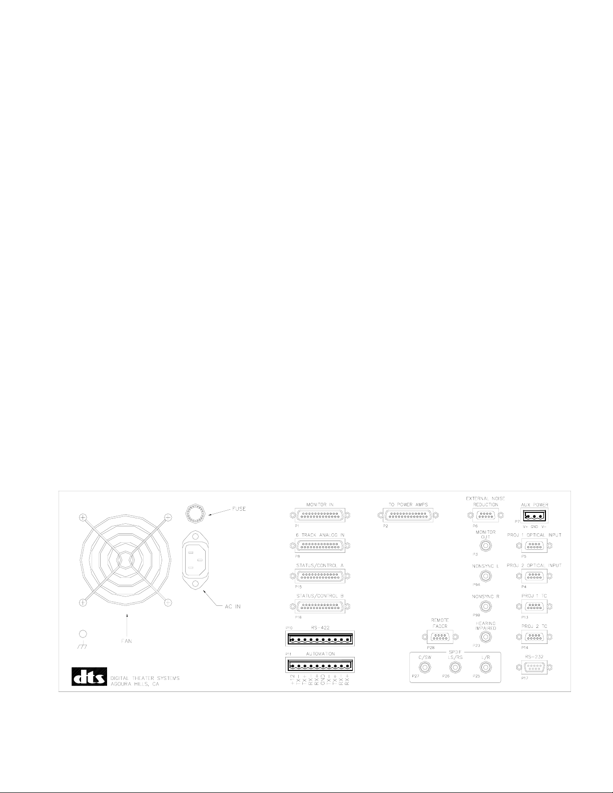
Drawing, DTS-ECP Rear Panel .………………………………………………………… 2-1
2.2. Connecting the DTS-ECP ………………………………………………………... 2-2
2.3. D744 Analog (
2.3.1.
2.3.2. Factory Settings ………………………………………………………….…………… 2-3
2.3.3. Changing the Jumper Settings ……………………………………………………….. 2-3
Drawing showing how to remove and hang front panel ………….…………..….…….. 2-4
Drawing showing what is behind the front panel ………………………….………..….
Fold-out drawing showing D744 jumper locations ………………..……….…………..
Jumper Functions …………………………………………………………………….. 2-3
2.4. Auxiliary DC Power Supply Connection …………………………………….….. 2-9
Drawing, Wiring DC Supply to AUX Connector ………………………………………… 2-9
2.5. Interfacing the DTS-ECP to other Sound Systems/Sources ……………………... 2-10
Automation Interfacing ………………………………………………….…….………. 2-10
External Crossovers …………………………………………………………………….. 2-10
Digital Amplifiers and Automation ……………………………………..……………. 2-11
External Microphone …………………………………………………………………… 2-11
NONSYNC
External Noise Reduction ………………………………………….……….…………. 2-12
External 6-Track ………………….…………………………………………………….. 2-10
DolbyTM Model DA20 ……………………………………………………..….………... 2-10
Internal Crossovers ……………………………………………………………………... 2-10
Remote Fader Option ….……………………………………………………………… 2-11
(Auxiliary) Monitor Speaker ………………………………………………..………… 2-11
DTS E342 Remote Control Panel ……………………………………………….. 2-12
2.6. Powering the DTS-ECP, Boot-Up Sequence …..……………………….………..
Drawing showing DTS-ECP after boot-up ……………………………………….. 2-12
bypass) Board Jumpers …………………………………………… 2-3
2-5
2-7
………………………………………………………………………….…………….. 2-11
2-12
i DTS P/N 9301DECP0002/10
Page 4

DTS-ECP Installation Manual Table of Contents
TABLE OF CONTENTS
SECTION PAGE
III. FRONT PANEL
3.1. DTS-ECP Front Panel ……………………………………………………………. 3-1
Drawing, DTS-ECP Front Panel ………………………….……………………………… 3-1
3.2. Control Format Keys ….………………..……………………………….……….. 3-1
3.3. Monitor Keys …………………………………………………………………….. 3-1
IV. DTS-ECP INITIAL SETTINGS
4.1. Setup Check List ………………………………………………………………….… 4-1
4.2. Surround Delay ……………………………………………………………………..
4.3. Speaker Time Alignment Delay ……………………………………………………. 4-3
4.4. Theater Equipment Check ………………………………………………………….. 4-4
4.5. Set Preliminary Output Levels ……………………………………………………..
4.6. Speaker Phase ………………………………………………………………………. 4-6
4-2
4-5
V. B-CHAIN ALIGNMENT
Drawing showing suggested microphone placement ……………….……..………………….. 5-1
5.1 Setting Output Levels …………………………………………………………..…. 5-2
5.1.1. Connecting a Calibrated Microphone or Mic Multiplexer ………………………. 5-2
5.1.2. Check DTS-ECP Programmed Output Levels ……………………………………. 5-2
5.1.3. Measure Preliminary Output Levels ……………………………………….………. 5-3
5.2. Room Equalization ……………………………………………………………….... 5-4
5.2.1. EQ Programming Procedure …………………………………………….…………. 5-4
5.2.2. Copying EQ Settings …………………………………………………….……….… 5-7
5.2.3. Surround Channels’ EQ ………………………………………………….………… 5-7
5.2.4. Sub Bass Parametric EQ ………………………………………………….…….….. 5-8
5.2.5. OBE Adjustment ………………………………………………………………..…… 5-10
5.2.6. Save EQ Settings ………………………………………………………………
5.2.7. Clearing EQ Settings ………………………………………………………….……. 5-13
5.3. Final Sound Level Adjustments …………………………………………………....
5.3.1. Final SPL Adjustment ……………………………………………………………… 5-14
5.3.2. Listen to Theater Speakers ………………………………….……………………… 5-14
VI. A-CHAIN ALIGNMENT
6.1. Aligning the Projector’s Analog Optics …………………………………………… 6-1
Drawing of A-Chain Test Equipment Setup………………..……………………………… 6-1
6.2. Optical Gain ……………………………………………………………………...… 6-2
6.3. Cell Alignment Check ……………………………………….………….………..… 6-3
6.3.1. Cell Alignment ………………………………………………………………………. 6-3
6.3.2. Crosstalk Stereo Alignment ……………………………………………….……….. 6-3
6.4. Slit Loss Compensation…………………………………………………………….. 6-4
6.5. Azimuth ……………………………………………………………………………. 6-5
6.6. MONO Adjustment ………………………………………………………………….…… 6-5
6.7. BYPASS Adjustment ……………………………………………………………..………. 6-5
6.8. Final Level Check ………………………………………………………………..... 6-6
5-13
5-14
ii DTS P/N 9301DECP0002/10
Page 5

DTS-ECP Installation Manual Table of Contents
TABLE OF CONTENTS
SECTION PAGE
VII. FINAL PROGRAMMING
7.1. CP Setup Software Menus ………………………………………………………….. 7-1
Format S
O
utput Trim ………………………………………………………………………… 7-3
EQ ………………………………………………………………………………….. 7-4
OB
Optical Setup ………………………………………………………….……………. 7-6
Opt
Theater I
H
elp ……………….…………………………………………………………….….. 7-8
7.2. Final Programming and Settings ……………………………………………………. 7-9
Assign F1 Key ………………………………………………………………………
NONSYNC Output Mode …………………………………………………………… 7-9
Power-On Format ……………………………………………………………………
Disable Matrix ……………………………………………………………………….
Remote Fader Option ………………………………………………………………..
DTS E342 Remote Front Panel Option …….…………….…………………………
Enter Theater Information ………………………………………………………….. 7-10
Keyboard Shortcuts …………………..………………………………………. 7-10
VIII. PERFORMANCE TEST AND OPERATION
8.1. DTS-ECP System Performance Test ………………………………………………. 8-1
8.1.1. DTS-ECP Test ………………………………………………………………………. 8-1
Verify Sound Performance ………………………………………………….……… 8-1
Verify BYPASS Operation …………………….…………………………………….. 8-2
Set Booth Monitor Adjustments ………….…………......…………………..… 8-2
8.1.2. External Equipment Performance with DTS-ECP ……………………………….. 8-3
External 6-Track Analog Source …………………………………………….…….. 8-3
Dolby
6-Track Magnetic Master ..………………………………………….……………………… 8-3
External Microphone ………………………………………………………………… 8-3
DTS E342 Remote Front Panel ………………….…………………………….
NONSYNC ………………………………………….………………………………………….. 8-3
8.2. Operation ……………………………………………………………………………
8.2.1. Before the Show ……………………………………………………………………... 8-4
8.2.2. During the Show …………………………………………………………………….. 8-4
BYPASS Mode Operation ..………………………………………………………….. 8-5
8.2.3. After the Show ………………………………………………….……………………. 8-5
iii DTS P/N 9301DECP0002/10
election ……………………………………………………………….…… 7-2
E (optical bass extension) ………………………………………………………. 7-5
ions ……………………………………………………………………………... 7-7
nformation ………………………………………………………………… 7-8
7-9
7-9
7-9
7-9
7-10
Channel Verification …………………………………………………………..……. 8-1
Automation …………………………………………………………………………… 8-3
TM
Model DA-20 ……………………………………………………………………... 8-3
Remote Fader ………………………………………………………………………… 8-3
8-3
8-4
Remote Fader Operation ..…………………………………………………………… 8-5
DTS E342 Remote Front Panel Operation ………………….………………… 8-5
Dual Projector Operation ……………………………………………………………. 8-5
Maintenance ………………………………………….………………………………. 8-5
Page 6

DTS-ECP Installation Manual Table of Contents
TABLE OF CONTENTS
SECTION PAGE
IX . WIRING DIAGRAMS
WDE237 System Wiring Diagrams ……………………………………………………. 9-2
SDE238 Remote Fader Schematic Diagram …………………………………………... 9-13
TI-D435 Timecode Reader Cable Wiring Diagram ……………….…………………... 9-14
X. TROUBLESHOOTING
10.1. Inside the DTS-ECP ……………………………………………………….……….. 10-1
Diagram, Inside the DTS-ECP ………………...…………………………………………… 10-2
10.2. User Troubleshooting Tips …………………………………………………………. 10-4
Drawing, Signal Path …………………………………………….…………………..……… 10-5
10.3. Technician Troubleshooting Guide ………………………………………………… 10-7
Display Anomalies ……………………………………………………………………..… 10-7
Logic Anomalies …………………………………………………………………….…… 10-9
BYPASS
Noise, Distortion, Other Sound Anomalies ………………………………….………... 10-10
Power Anomalies …………………………………………………………………..…….. 10-7
Anomalies …………………………………………….…………………...……. 10-9
Monitor Anomalies ………………………………………………………………..……… 10-9
Laptop (PC) Anomalies ……………………………………………...………. 10-11
10.4. Updating DTS-ECP Internal Software ..…………………………………………… 10-12
10.5. Updating DTS CP Setup Software …………………………………………………
10.6. DTS Technical Support …………………………………………………………….. 10-12
10-12
XI. APPENDICES
Appendix A: Back Panel Connector Pin-Outs
P1 Monitor In ……………………………………………………………..
P2 To Power Amps ………………………………………………………. A-3
P3 Monitor Out …………………………………………………………… A-4
P4
& P5 Projector 1 & Projector 2 Optical Inputs ……………………………… A-4
P6 External Noise Reduction …………………………………………….. A-5
P7A Auxiliary Power ………………………………………………………. A-5
P8 6-Track Analog In ……………………………………………………..
P9A/B NONSYNC Left & Right In ……………………………………………. A-7
P10A/B RS-422 ………………………………………………………………… A-8
P11A/B Automation ……………………………………………………………. A-8
P13 Projector 1 TC (timecode) ……………………………………………. A-9
P14 Projector 2 TC (timecode) ……………………………………………. A-9
P15 & P16 Status / Control A & B ………………………………………………… A-10
P17 RS-232 ………………………………………………………………… A-8
P23 Hearing Impaired Out ………………………………………………… A-7
P25 L/R SPDIF Out ………………………………………………………. A-9
P26 LS/RS SPDIF Out ………………………………………………….… A-9
P27 C/SW SPDIF Out …………………………………………………….. A-9
P28 Remote Fader …………………………………………………………. A-7
(continued)
A-2
A-6
iv DTS P/N 9301DECP0002/10
Page 7

DTS-ECP Installation Manual Table of Contents
TABLE OF CONTENTS
SECTION PAGE
XI. APPENDICES (continued)
Appendix B: D744 Analog (bypass) Board Jumper Settings
Main Audio Outputs: Balanced or Unbalanced ……………………………..…….
Screen Channel Outputs: Wideband or Bi-Amped ………………………..….…... B-3
Screen Channel Time Alignment Delay ………………………………….…….….
Screen Loss Compensation Equalization ……………………………….…………. B-5
External Noise Reduction: Balanced or Unbalanced ……………………..……….
Booth Monitor Power-On State ……………..………………………….…………. B-7
Crossover Resistor Packs ……………………………………………………….….
.
Appendix C: DTS-ECP System Replacement Parts List ……………………………. C-1
Appendix D: Marquee Order Form ………………………………………………….. D-1
Appendix E: RT-60 Test Section ……………………………………………………. E-1
Appendix F: Using the DTS Upload/Download Software Program ………………… F-1
Appendix G: DTS-ES Wiring to DTS-ECP ………..………………..…..….………. G-1
Appendix H: Installing and Using the DTS CP Setup Software ………………….… H-1
Keyboard Shortcuts …..…………………………………………… H-2
Appendix I: Ground Loop Isolator for the DTS-6AD/-ECP ………..……………... I-1
Appendix J: Installing DTS Digital, Model DPP to DTS-ECP ..……………...…… J-1
Appendix K: Motherboard D742 Revision K and Earlier ……….……………...…… K-1
Appendix L: Adjusting the Optical Levels Without a PC …………………………… L- 1
B-2
B-4
B-6
B-8
v DTS P/N 9301DECP0002/10
Page 8

DTS-ECP Installation Manual Table of Contents
NOTES
Thank you for choosing DTS !
vi DTS P/N 9301DECP0002/10
Page 9

DTS-ECP Installation Manual Section 1, Introduction And Specifications
SECTION 1 INTRODUCTION AND SPECIFICATIONS
1.1. ABOUT THE DTS-ECP
1.1.1. How the DTS-ECP Works
The DTS-ECP is an expandable cinema processor that enables playback of motion picture
sound tracks. The standard unit combines the functions of a 6-track analog sound processor and
booth monitor. The unit is capable of audio playback in stereo optical (A-type or SR-type noise
reduction
), mono, and (stereo) NONSYNC formats. It also allows for automation interfacing and
playback of an external 6-track source. The unit has individual channel controls and emergency
BYPASS Mode. Individual channel EQ accomplished by the use of a laptop PC and DTS CP Setup
Software. The unit can be configured (via jumpers) for external or internal crossovers. WIDEBAND
is used for external and when internal is used, the customer specifies the resistor pack value
required. Other programmable (via jumpers) features include: Balanced or unbalanced external
NR, balanced or unbalanced output, screen loss EQ, and time alignment delay.
The unit is designed to be “expandable” meaning that DTS digital playback can be added as an
option. This option is added by installing the Model DPP.
1.1.2. Adding DTS Digital Upgrade (Model DPP, Digital Processing Package)
When the DTS digital package (Model DPP) is added, the following items are changed: Addition
of three CD-ROM drives, the front display is changed, software is changed, and the CPU board is
changed. A DTS timecode reader and cable will be issued as well as one reader for platter
systems and two readers (with ”Y” cable) for dual projectors (change-over systems).
Once DTS digital is added, the DTS-ECP uses DTS time-coded film to synchronize DTS digital
6-track sound (on DTS movie discs) to each frame of film projected. The DTS reader sends
timecode information on the film to the DTS-ECP. The DTS-ECP uses the timecode to play the
correct sound, on matching movie discs loaded into its CD-ROM drives, to the picture projected.
The projectionist simply inserts the movie disc(s) into the DTS-ECP and threads the film though
the DTS timecode reader. Once the film is started, the DTS system checks a keyed serial number
in the timecode and on the movie disc(s) to assure the correct sound is being played with the
movie being shown. Films released in the DTS digital sound format also contain a traditional
analog (optical) sound track (SR, A-TYPE, or MONO) which serves as a back-up sound source. If a
problem occurs in the DTS digital playback, the DTS-ECP switches out of digital and reverts to
the analog sound format that the film was recorded in. And at the end of the show, the DTS-ECP
automatically switches from DTS digital playback to
NONSYNC.
The DTS digital sound process for motion pictures is designed for the digital sound release of
motion pictures in 6-track theaters. It is a dual system in that the digital audio data is recorded on
CD-ROM discs. DTS timecode is printed on the motion picture print along with a conventional
stereo optical soundtrack. The timecode is used by the DTS system to synchronize the sound and
picture. The timecode lies between the picture and optical sound track, and is printed onto the
release print from the soundtrack negative. There is a single inventory of prints.
1 - 1 DTS P/N 9301DECP0002/10
Page 10

DTS-ECP Installation Manual Section 1, Introduction And Specifications
1.1.3. After DTS Digital (Model DPP) is Added
The DTS digital provides left, center, right, stereo surrounds, and subwoofer channels. The
system allows for play times up to 5 hours. They are completely automatic and fail-safe in
operation requiring no action by the projectionist. The systems automatically start and stop, and
track film breaks and change-overs. The digital audio data is sampled at 44.1K samples per
second. APTX100 digital audio data compression (4:1) is used. Transfer into the process can be
made from conventionally mixed analog or digital sound masters.
1.1.4. DTS-ECP Standard Features
The following standard features are available on the DTS-ECP system:
y Two stereo optical pre-amplifiers
y Dual projector ready
y Dual status and control connections to automation systems
y Selectable crossovers: Internal or external. If internal, customer selects value when ordering.
y Both SR-TYPE & A-TYPE optical and MONO sound formats, NONSYNC, and external 6-track
y Sound format control switches and status display
y Front panel BYPASS mode indicator light, master fader level display and volume control
y Built-in booth monitor speaker, volume control, and channel select switches
y External noise reduction loop
y Internal pink noise generator
y Automatic adjust AC input from 85 VAC to 264 VAC between 47 Hz and 64 Hz
y Auxiliary (DC) power input
y L, C, R mix (center weighted) hearing impaired output
y NONSYNC stereo input
y Remote fader and DTS remote front panel (E342) connections
y Magnetic sound print master ready: Stereo, Lt/Rt (4:2:4 matrix), or 6-track
y Programmable (via jumpers) surround speaker delay
y Automatic emergency BYPASS functions
y Individual channel level controls
y Individual channel equalization via DTS CP Setup Software (WINDOWS
PC customer supplied)
(
TM
based) and laptop PC
y DTS 70mm capable. Used with special order DTS 70mm readers.
y Trim feature allows user to balance volume of feature film and trailers
y RS232 connection to laptop PC To run DTS CP Setup Software.
y SP/DIF digital audio 6-track output
y RS422 communications to automation systems (future)
1.1.5. DTS Digital (Model DPP) Features
y One DTS 35mm timecode reader standard; 70mm, second reader (for dual projector) special order
y DTS 6-track digital output = 5.1 standard and 6.0 special order
y Three CD-ROM drives
y Full status display and software programming screen
y Expanded audio software programs (as available on DTS-6AD unit).
1 - 2 DTS P/N 9301DECP0002/10
Page 11

DTS-ECP Installation Manual Section 1, Introduction And Specifications
1.2. DTS-ECP TECHNICAL SPECIFICATIONS
Frequency Response y L, C, R: 20 Hz to 20 kHz
y LS and RS: 80 Hz to 20 kHz
y Sub bass: 20 Hz to 80 Hz
Dynamic Range: 96 dB, all channels
Size: y 7 inches [17.78 cm] high (4 rack units)
y 19 inches [48.26cm] long rack mount
y 15½ inches [39.37cm] deep
Weight: 28 LBS. [10.45kg] (includes unit, shipping carton, accessories, and manual)
Fuse (AC supply) 2 amp slow blow, 3AG
Digital EQ: y Screen channels: Third octave EQ bass and treble
y Surround channels: One octave EQ bass and treble
y Subwoofer: Selectable one-2/3-1/3 octave EQ. OBE may be disabled, if desired
Analog Input: y D744 jumper selectable: Balanced or unbalanced, all 6 channels and external
noise reduction loop
y D744 jumper selectable: Normal or bi-amped, all 6 channels
y D744 jumper selectable: Time alignment for screen channels
y D744 jumper selectable: Screen loss compensation, screen channels only
External 6-track
Analog Input: Balanced 300mV
AC input: 85 VAC to 264 VAC between 47 Hz and 64 Hz
Internal Crossover y 500Hz, 800Hz, 1200Hz standard.
Selections: y Other frequencies available by special order
Automation Two Status/Control connections available, P15 and P16. See Appendix A for
details. P11 (RS422 to digital automation systems) not enabled at this time.
Internal Noise
Reduction: Two channels each for
SR-TYPE and A-TYPE optical sound formats
External Noise Balanced or unbalanced (D744 jumper selectable), 300mV
Reduction In/Out:
External Microphone Unbalanced 300mV (although there is not a dedicated connector for this feature, it can be
Input Level: accomplished several ways, see Section 2).
NONSYNC Input: Unbalanced, 300mV level for left and right channels
Hearing Impaired Unbalanced, 300mV output: Center weighted mix of Left, Center, and Right
Output: channels.
External Speaker Out: Requires 8 ohms, self-powered. DTS-ECP outputs 300mV nominal signal.
Auxiliary Power In: Requires ±12 VDC to ±15 VDC at 2 amps. Used for emergency back-up power.
1 - 3 DTS P/N 9301DECP0002/10
Page 12

DTS-ECP Installation Manual Section 1, Introduction And Specifications
1.2. DTS-ECP TECHNICAL SPECIFICATIONS (continued)
An external six-track analog input is available for a 300mV external source. The two status/control
connectors connect to theater’s automation system and to external digital playback systems for sense and
control functions. An external noise reduction loop connection is selectable for balanced or unbalanced
and can be fed into external noise reduction or to output another Lt/Rt signal such as magnetic printmaster playback. Matrix may be disabled through software programming, for pure stereo playback.
The main output provides user selectable wideband or bi-amped outputs. Jumpers on D744 analog
board allow use of outputs for THX sound systems or speakers with built-in crossovers. If internal
crossovers are desired, plug-in resistor headers determine crossover frequency: 500Hz, 800Hz, and
1200Hz standard, other frequencies can be special ordered. Jumpers also select balanced or unbalanced
outputs for all channels, as well as screen loss compensation and time alignment delays for the screen
speakers.
Equalization for screen channels and surrounds is accomplished with laptop PC and DTS CP Setup
Software
in the digital domain along with both A-type and SR-type noise reduction. Three SP/DIF digital
audio pairs are available for left, center, right, subwoofer, and left & right surrounds.
B-chain alignment is easily accomplished via a laptop PC and DTS CP Setup Software (WINDOWSTM
based). Each channel has bass and treble control as well as third/single-octave EQ adjustments. Individual
output levels are set with trim-pots, and on-screen level adjustment allows SPL fine-tuning.
A-chain alignment is easily accomplished using test film, a laptop PC, and DTS CP Setup Software.
Separate solar cell adjustments are available for the two projector inputs.
Built-in booth monitor buttons select one or a combination of all six output channels, and are selectable
between DTS-ECP output and return from power amps. An additional button turns internal speaker
on/off. An external speaker connector is available on the rear panel (“MONITOR OUT”).
There is an overall master fader on the front panel and remote fader connections on the rear panel. Also
on the rear, is a remote front panel connection (
made for DTS E342, Remote Control panel).
A
NONSYNC source connector is available and its trim level is menu driven. NONSYNC signal routing can
be used for audio coverage when curtains are closed.
While in the
BYPASS mode, the signal from the solar cell is routed to the screen channels, and a separate
trimpot on the D744 board is used to adjust volume. A toggle switch (on the D744 board) can enable the
BYPASS mode. The DTS-ECP will also automatically go into the BYPASS mode if a fault occurs on CPU
or DSP boards. When BYPASS is enabled, a red LED (on the D744 board) lights to indicate the DTS-ECP is
in the BYPASS mode. The D744 board is located behind the control module on the front panel.
A universal fused power supply allows connection to all AC power sources. A standard power cord is
provided. An optional DC supply may be used via the “AUX POWER” connector and is used for
emergency backup power (
±12 VDC to ±15 VDC at 2 amps).
1 - 4 DTS P/N 9301DECP0002/10
Page 13

DTS-ECP Installation Manual Section 1, Introduction And Specifications
1.3. REGULATORY NOTICES
EMI NOTICE
This equipment has been tested and found to comply with the limits for a Class A digital device, pursuant
to Part 15 of the FCC Rules. These limits are designed to provide reasonable protection against harmful
interference when the equipment is operated in a commercial environment. This equipment generates,
uses, and can radiate radio frequency energy and, if not installed and used in accordance with the
instruction manual, may cause harmful interference to radio communications. Operation of this
equipment in a residential area is likely to cause harmful interference in which case the user will be
required to correct the interference at his own expense.
Canadian Department of Communications compliance statement:
This equipment does not exceed Class A limits per radio noise emissions for digital apparatus set out in
the Radio Interference Regulation of the Canadian Department of Communications. Operation in a
residential area may cause unacceptable interference to radio and TV reception requiring the owner or
operator to take whatever steps are necessary to correct the interference.
Avis de conformite aux normes du ministere des Communications du Canada:
Cet equipment ne depasse pas les limites de Classe A D'emission de bruits radioelectriques pour les
appareils numeriques telles que perscrites par le Reglement sur le brouillage radioelectrique etabli par le
ministere des Communications du Canada. L'exploitation faite en milieu residentiel peut entrainer le
brouillage des receptions radio et television, ce qui olbigerait le proprietaire ou l'operateur a prendre les
dispositions necessaires pour en eliminer les causes.
The DTS system has been granted the following patents:
United States of America Patent Nos. 5155510, 5386255, 5450146, 5751398
Australia Patent Nos. 652965, 661614
Europe Patent Nos. 0551424, 0615631, 0473677, 0632922, 0666495
Japan Patent Nos. 2033555, 2708961
India Patent No. 181427
Russia Patent No. 2088962
Korea Patent Nos. 153028, 0185423
France Patent Nos. 8906807, 9114963
Canada Patent No. 2016028
As of July 16, 1999
PATENTS
1 - 5 DTS P/N 9301DECP0002/10
Page 14

DTS-ECP Installation Manual Section 1, Introduction And Specifications
1.4. UNPACKING
The packaging is designed to handle normal shipping and handling. Upon receipt of shipment, check for
signs of damage before opening and report all damage to the carrier. All shipments made from DTS are
customer responsibility once they leave our premises.
Before installation is begun it is suggested that a complete inventory be taken to minimize problems or
questions during installation. Additionally, save all packing material until installation is complete in the
unlikely event that a component(s) requires return to the factory. Use the packing slip that came with
your unit to verify received inventory.
The following is a sample packing list:
• DTS-ECP processor and power cord
• Installation Hardware (mounting screws, and two each 25-pin & 9-pin “D” connectors w/solder cups)
• Manual
NOTES:
Reader head(s) provided when system upgraded to “digital”
If any of the items on your packing list cannot be found in shipping carton, contact DTS with the P/N and
description of the missing item(s). Refer to “
RETURNS,” before sending any product back to DTS.
RETURNS
For warranty repair, exchange or getting replacement parts, please call your local DTS office or dealer.
A DTS Return Authorization number is required before sending any item back to the factory. At the
time of the call, DTS will require that you provide the serial number of any unit(s) or reader(s) for return
before warranty replacement units will be sent. All return packaging should be clearly marked with the
Return Authorization number on the outside of the package.
Please send all returns to:
North America Europe
Digital Theater Systems, Inc. DTS SA
5171 Clareton Drive Unit 5, Tavistock Industrial Estate
Agoura Hills, California 91301-4523 USA Ruscombe Lane
Telephone: (818) 706-3525 Twyford, Berkshire RG10-9NJ UK
or toll free in USA: 800-959-4109 Telephone: 44-1189-349199
Customer Service Fax: (818) 879-2746 Fax: 44-1189-349198
Japan
DTS Japan (Liaison Office)
AT Communications KK
2-14-4 Shinonome, Koto-ku
135-0062 Tokyo, Japan
Telephone: +81(0)3.5564.7156
Fax: +81(0)3.3520.1022
1 - 6 DTS P/N 9301DECP0002/10
Page 15

DTS-ECP Installation Manual Section 1, Introduction And Specifications
FACTORY WARRANTY FORM
The following is a list of information necessary for every location where the DTS-ECP system is
installed.
THEATER NAME / CIRCUIT: _________________________________________
THEATER LOCATION: _________________________________________
SCREEN NUMBER: _________________________________________
THEATER CONTACT / TELE #: _________________________________________
LOCAL TECH / TELE #: _________________________________________
DTS-ECP SERIAL NUMBER: _________________________________________
PROJECTOR TYPE: Single Dual (circle one)
CROSSOVERS: (circle one) EXTERNAL INTERNAL ___________ ohms
SPEAKER SYSTEMS SOUND AMPLIFIERS
Screen (model): _______________________________ Amp (model): __________________________
Surrounds (model): _____________________________ Amp (model): ___________________________
Subwoofer (model): ____________________________ Amp (model):___________________________
Surrounds: ___________________________________ Subwoofer: self powered? _________________
DTS requires the above information in order to provide you proper and timely technical support.
PLEASE fill page out and send to DTS, attention Customer Service, fax
Digital Theater Systems, Inc.
5171 Clareton Drive
Agoura Hills, California 91301-4523 USA
Telephone: (818) 706-3525 / (800) 959-4109
www.dtsonline.com
(toll free USA only)
Thank you for choosing DTS!
(818) 879-2746.
1 - 7 DTS P/N 9301DECP0002/10
Page 16

DTS-ECP Installation Manual Section 1, Introduction And Specifications
1.5. WARRANTY INFORMATION
Equipment manufactured by Digital Theater Systems, Inc. is warranted against defects in materials and
workmanship for one year from date of purchase. There are no other expressed or implied warranties.
Digital Theater Systems, Inc. obligation is restricted to repair and replacement of defective parts. Under
no circumstances will Digital Theater Systems, Inc. be liable for any other damage, either direct or
consequential.
All requests for repairs or information should include the unit serial number to ensure rapid service.
1.6. DTS AUTHORIZED SERVICE CENTERS
DTS has service centers around the world. Please contact your local DTS office for more information.
1.7. DTS TECHNICAL SUPPORT
North America (corporate headquarters in California)
Telephone: (818) 706-3525 or continental USA: (800) 959-4109
Fax: (818) 706-1868
DTS engineers are available to assist you. If you have an emergency after business hours, please
leave a message on the answering service and we will return your call as soon as possible.
Europe (UK)
Telephone: +44-1189-349199
Fax: +44-1189-349198
Japan
Telephone: +81(0)3.5564.7156
Fax: +81(0)3.3520.1022
INTERNET users may email DTS technical support at the following address:
cinematech@dtsonline.com
DTS Web Site address:
www.dtsonline.com
In the web site, there is a section called “cinema” “techcenter” that contains product information,
manuals, technical bulletins, and email access to DTS field engineers. Use of this information is
free to all internet users. Everyone is required to fill out the on-line questionnaire before access to
the “techcenter” is granted. Once the questionnaire is completed, you will receive instant access
to the DTS ‘techcenter’ and a password.
1 - 8 DTS P/N 9301DECP0002/10
Page 17

DTS-ECP Installation Manual Section 1, Introduction And Specifications
1.8. REQUIRED EQUIPMENT, TEST FILM, and TOOLS
EQUIPMENT
The following equipment is required:
• DTS CP Setup software
• Real Time Analyzer (customer provided)
• Single calibrated microphone or mic multiplexer with set of calibrated microphones
• Laptop PC and a null modem cable (customer provided)
• DTS Upload/Download software
• SPL meter (customer provided)
• Oscilloscope (customer provided)
• DTS technician’s kit (purchased separately, not included with the DTS-ECP)
The kit is required to adjust and check the DTS digital format. It consists of:
) DS1, 6-track Setup *Disc. To verify digital levels, check automatic default switching, and verify operation of
CD-ROM drives (when installed)
the
) “Buzz and Bill Show” Film and *Disc. To test the performance of DTS-ECP
) Empirical Test *Disc. To test theater’s sound system through the DTS-ECP (when DTS Digital installed)
) DTS trimpot tweeker. To adjust level trim pots
) DTS T-Shirt. So you’ll be looking good !
NOTES: *Disc requires the DTS Digital option to be installed.
TEST FILM
The following test films will be required to adjust and check the (A-chain) optical formats:
• 50% modulation tone test film
• Pink noise test film
• Buzz track film
• 1 kHz cross-talk cell alignment film
TOOLS
The following tools will be needed:
• Scope probe and test leads for A-Chain adjustment. The test leads should have dual-ended plugs
at 0.080 inches long and be 2mm in diameter (
• Multimeter
• Flat-bladed and Phillips screwdrivers, various sizes
• Adjustable wrench
• Wire cutters and strippers
• Soldering iron and solder
• Pliers
• Electrical tape
• Flashlight
example: Pomona 3901 or 3221).
1 - 9 DTS P/N 9301DECP0002/10
Page 18

DTS-ECP Installation Manual Section 1, Introduction And Specifications
NOTES
Thank you for choosing DTS !
1 - 10 DTS P/N 9301DECP0002/10
Page 19
DTS-ECP Installation Manual Section 2, Installation, Jumpers, and Interfacing
SECTION 2 INSTALLATION, JUMPERS, AND INTERFACING
2.1. INSTALLING THE DTS-ECP INTO THE SOUND RACK
DTS-ECP expandable cinema processor is designed to mount into a standard 19” wide sound rack. The
processor is 7" (4U) tall and 17" deep. Select a space in the sound rack where the processor will be at eye
level for most operators. Bolt the DTS processor into the rack. One rack unit of space should remain
open above and below the unit in observance of ventilation requirements.
• The ambient temperature within the rack may be greater than room ambient temperature. The
maximum temperature for the equipment in this environment is 50°C. Consideration should be
given to the maximum rated ambient.
• Installation should be such that the amount of air flow required for safe operation is not
compromised, and that a hazardous condition is not achieved due to uneven loading.
• Check nameplate ratings to assure there is no overloading of supply circuits that could have an
effect on over-current protection and supply wiring.
• Reliable grounding of this equipment should be maintained. Particular attention should be given
to supply connections when connecting to power strips, rather than direct connections to the
branch circuit. Connect earth ground wire to #6 terminal provided on the DTS-ECP back panel.
• A quality surge / spike suppresser power strip is recommended to protect the DTS-ECP processor.
• Never block the side vents of the DTS-ECP. Free air flow within the unit prevents over-heating
and keeps dirt from being sucked in through the CD-ROM drives (when installed).
2 - 1 DTS P/N 9301DECP0002/10
Page 20

DTS-ECP Installation Manual Section 2, Installation, Jumpers, and Interfacing
2.2. CONNECTING THE DTS-ECP
Refer to Section 9 Wiring Diagrams or Appendix A Pin-out Tables when making cables. Connections to
the DTS-ECP are made primarily via 9-pin or 25-pin “D” connectors, Phoenix and RCA-type connectors.
• Ensure that the DTS-ECP front panel power switch is in the OFF position.
• Lift off the display panel and verify that all three circuit cards are fully inserted.
The solar cell from the projector is connected to P5 “PROJ 1 OPTICAL INPUT”. If there is a second
projector, it is connected to P4 “PROJ 2 OPTICAL INPUT”. Connect a (DTS supplied) ferrite suppressor
around each cable going to a solar cell (on projector).
Main audio output is available at P2 “TO POWER AMPS”. This connector contains 12 output signals:
High and low frequency outputs for bi-amping each of the six channels. Installations with external
crossovers use the wideband (HF) outputs only (LF outputs are not used for wideband applications). The
D744 analog board jumpers must be set for either “bi-amp” or “wideband”. See Section 2.3
The internal crossover frequency is set by plug-in crossover resistor packs in D744. Consult speaker
manufacturer for crossover frequency requirement. See Appendix B for available resistor packs – these
must be removed if using unit in WIDEBAND mode.
To verify sound at the speaker amps, connect their outputs to P1 “MONITOR IN”. The enables the use of
the front panel monitor speaker and its selector switches. Wideband applications use P1 HF inputs only.
As the built-in monitor speaker is for reference only, it will be desirable to attach a self-powered
amplified speaker to the P3 “MONITOR OUT” RCA-type connector. The addition of an auxiliary monitor
speaker provides higher volume capabilities and better frequency response.
A NONSYNC source, such as a CD player, connects to P9A “NONSYNC L” and P9B “NONSYNC R” inputs.
These are RCA-type connectors and accept 300mV (line level) unbalanced signal. The NONSYNC signal
can be a normal stereo or matrix encoded source.
Timecode connectors are not used until the DTS Digital (Model DPP) is added.
Any six-track analog source at a 300mV can be connected to P8 “6-TRACK ANALOG IN”.
Format pulses from an automation system are connected to either P15 “STATUS/CONTROL A” or P16
“STATUS/CONTROL B”. Any of the six formats, mute, trim feature, or projector changeover can be
selected from this connector. These connectors also contain LED drive voltages for a remote front (or
status)
panel. NOTE: At this time, the RS422 connectors are not useable with digital automation.
P23 “HEARING IMPAIRED” output provides a center-weighted mix of the left, center, and right channels
for use with a hearing impaired sound system.
Connect the AC power cable to the DTS-ECP processor. (NOTE: The DTS-ECP processor is a computer
based system and as such can be susceptible to power line surges. A good quality surge and spike
suppressor made for computers is recommended). Two power supplies provide power to the DTSECP unit. Both supplies are fused and automatically adjust to incoming AC mains voltages: From 100
VAC to 240 VAC, between 50 and 60 Hz.
If using a DTS E342 remote front panel, connect it to P11A/B RS422 connector (either one).
If using a remote fader, connect it to P28 REMOTE FADER connector.
2 - 2 DTS P/N 9301DECP0002/10
Page 21

DTS-ECP Installation Manual Section 2, Installation, Jumpers, and Interfacing
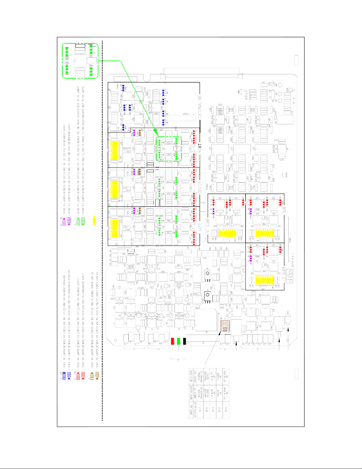
2.3. D744 ANALOG BOARD JUMPERS
Jumper Functions
Before powering the DTS-ECP, verify the jumpers on the D744 analog board are set for your
application. The D744 board is programmable (
via jumpers) for the following operations:
• Balanced or Unbalanced output for all six channels Surrounds and sub don’t use crossovers
• Wideband or Crossover output for all six channels for 5.1, are available for 6.0 operation.
• Screen loss compensation for Left, Center, and Right channels
• Time alignment delay for Left, Center, and Right channels
• Balanced or Unbalanced input and output for external NR connector
• Wake-up state of the booth monitor (Rev. J D744 boards use dip switch instead of jumpers)
Factory Settings
Unless specified otherwise, the DTS-ECP will be shipped with the following settings:
• Balanced Output
• Wide-band Output
• Screen Loss Compensation = OUT
• Time Alignment Delay = OUT
• Balanced Input and Output for External NR connector
• Booth Monitor Wake-up Mode:
* Left, Center, Right = On, Surrounds & Sub = Off
* AMPS = Off
* Internal Speaker = On
If any of the defaults are not the required configuration, change the jumpers accordingly. Use the
“Jumper Settings” tables in Appendix B or drawing on 2-7 to identify and change the correct jumper.
Changing the Jumper Settings
• Turn off the power. The DTS-ECP must not be powered when removing the boards.
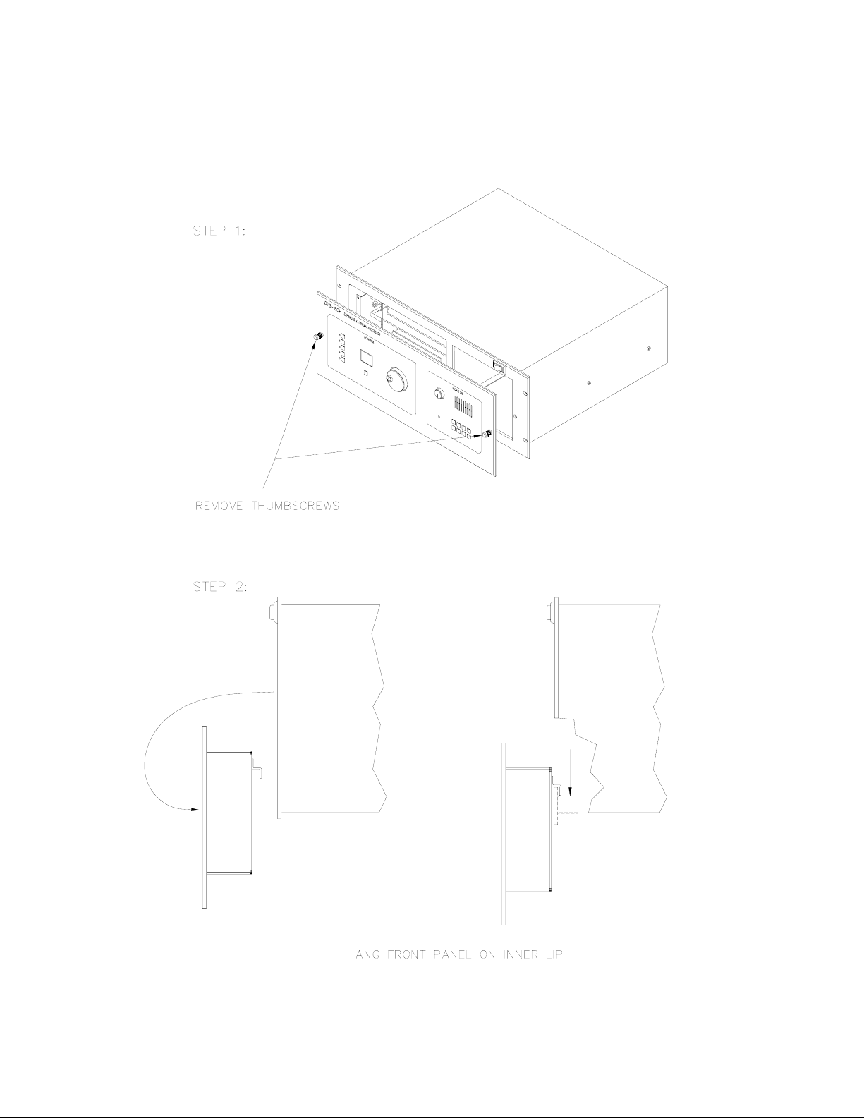
• Remove the front panel by turning the thumbscrews counter-clockwise. Once the screws are
released from their sockets, the front panel can be removed and hung on the front of the chassis by
hooking its side catches to the two inside studs of the chassis opening. See drawing on page 2-4.
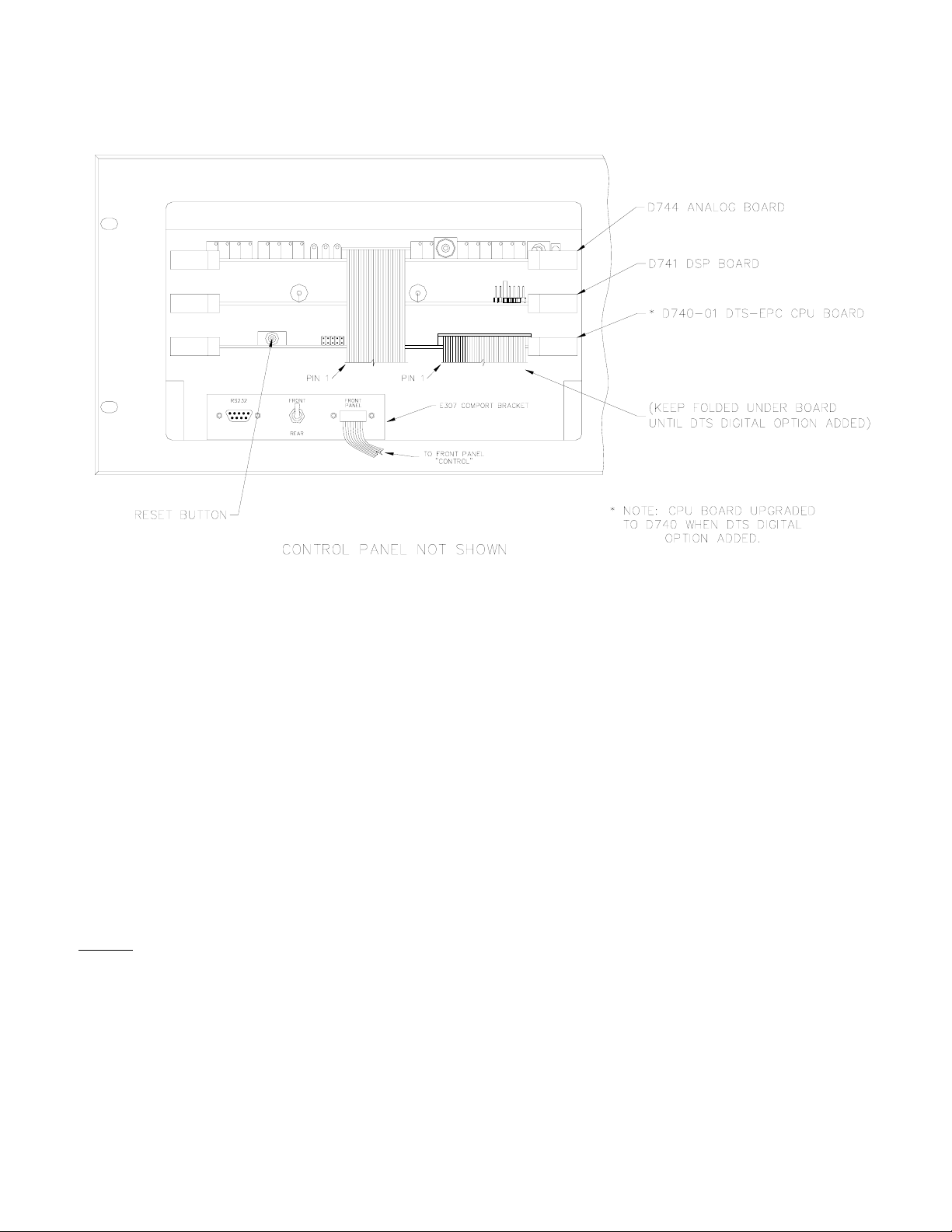
• There are three circuit boards behind the front display. The top board is the D744 analog board. It
contains the jumpers and crossover headers that the user can modify. The middle D741 board is
for Digital Signal Processing. The bottom D740 board is for CPU functions, stores software
memory, and contains the
RESET button. The middle and bottom boards require no adjustments
and contain no user serviceable parts. They should not be removed during setup..
• Remove the smaller of the two ribbon cables (24-pin) from the display. This cable is permanently
attached to the D744 board (top circuit board).
• The D744 board can now be removed by gently lifting the white levers on each side. You may
now gently slide the D744 board out from the chassis. Do not pull it out by the ribbon cable.
• To change D744 settings, use drawing on page 2-7 to find appropriate jumpers and crossover
headers. This information is also in Appendix B tables and charts.
2 - 3 DTS P/N 9301DECP0002/10
Page 22
DTS-ECP Installation Manual Section 2, Installation, Jumpers, and Interfacing
How to remove and hang the front panel
2 - 4 DTS P/N 9301DECP0002/10
Page 23
DTS-ECP Installation Manual Section 2, Installation, Jumpers, and Interfacing
What is behind the front panel
There are two RS232 ports on the DTS-ECP. One is located on the rear panel and the other on the
COMPORT panel, shown above. Both perform the same function of interfacing the DTS-ECP to a PC.
Using a null modem cable, connect the serial port of your PC to either the front or back RS232 connector.
Use one or the other, do not use both at the same time. After the DTS-ECP is fully booted, you may now
start the DTS Upload/Download program or the DTS CP Setup Software program on your PC.
The switch on COMPORT panel is selectable for front or back:
y Set to” back” when choosing to use the rear panel RS232 connector
y Set to “front” when choosing to use the RS232 connector on the
COMPORT panel
The “FRONT PANEL” cable connects to the front “CONTROL” panel.
The
RESET button on D741 is used to reboot the DTS-ECP.
NOTE:
* The DTS-ECP
D740-01 CPU board is not compatible with the D740 CPU board used on a DTS-6AD.
2 - 5 DTS P/N 9301DECP0002/10
Page 24

DTS-ECP Installation Manual Section 2, Installation, Jumpers, and Interfacing
NOTES
Thank you for choosing DTS !
2 - 6 DTS P/N 9301DECP0002/10
Page 25
DTS-ECP Installation Manual Section 2, Installation, Jumpers, and Interfacing
K
C
A
B
S
L
I
A
T
E
D
R
O
F
B
X
I
D
N
E
P
P
A
E
E
S
D
E
P
M
A
-
I
B
R
O
D
N
A
B
E
D
I
W
D
E
C
N
R
A
N
L
A
L
B
A
N
N
U
R
E
R
T
O
X
E
D
E
R
C
O
N
F
A
L
A
B
S
Y
R
A
L
E
E
V
D
O
S
T
S
S
N
G
O
E
N
I
R
M
T
C
N
T
E
G
I
S
L
A
E
M
I
T
I
I
I
H
H
N
N
-
-
I
I
L
R
A
A
G
G
-
L
R
R
O
T
C
1
E
J
O
R
P
Q
D
E
E
C
S
N
S
A
O
L
L
A
N
B
T
E
N
U
E
U
P
R
T
R
C
U
O
S
O
D
E
C
N
A
L
A
B
I
H
H
N
N
-
-
I
I
L
R
A
A
G
G
-
L
R
T
T
R
O
T
C
2
E
J
O
R
P
D
L
R
N
G
T
S
E
S
T
T
L
N
I
A
O
C
I
S
P
T
L
I
P
A
O
T
E
D
R
O
F
B
X
I
D
N
E
P
P
A
E
E
S
R
I
O
D
-
L
-
P
I
H
M
A
H
R
T
O
O
T
I
O
N
B
O
M
C
L
L
E
V
E
L
S
S
A
P
Y
B
R
E
T
O
S
A
T
I
N
T
N
O
S
I
O
T
P
M
C
U
-
E
H
E
L
T
K
E
O
A
S
O
W
B
B
S
U
S
S
L
R
R
S
T
U
P
T
U
O
N
I
A
M
H
R
C
O
T
T
I
A
W
C
I
S
D
D
S
N
E
S
I
L
A
S
P
S
Y
A
B
P
T
Y
N
B
O
R
F
2 - 7 DTS P/N 9301DECP0002/10
Page 26

DTS-ECP Installation Manual Section 2, Installation, Jumpers, and Interfacing
This page is purposely left blank so pervious page can be sized 11x18 and folded
2 - 8 DTS P/N 9301DECP0002/10
Page 27
DTS-ECP Installation Manual Section 2, Installation, Jumpers, and Interfacing
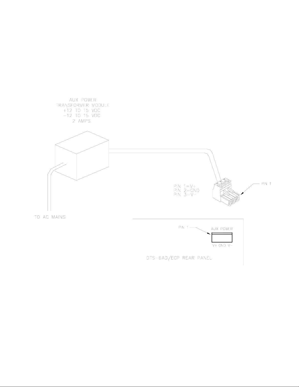
2.4. AUXILARY DC POWER SUPPLY CONNECTION
A separate 3-pin Phoenix connector is available for emergency power. A backup supply is highly
recommended for failsafe operation. The BYPASS circuits on the D744 board require voltage of
+12 VDC and –12 VDC to operate. If the internal power supplies fail, an external DC supply
that has both positive and negative output is required. It connects to the rear panel AUX POWER
P7A via a 3-pin Phoenix connector.
2 - 9 DTS P/N 9301DECP0002/10
Page 28

DTS-ECP Installation Manual Section 2, Installation, Jumpers, and Interfacing
2.5. INTERFACING TO OTHER SOUND SYSTEMS/SOURCES (see WDE237, Section 9)
Automation Interfacing
The “STATUS/CONTROL” connectors are available for interfacing to automation systems.
External 6-Track
The 6-TRACK ANALOG IN connector, P8, on the back of the DTS-ECP, can receive any 300mV
50% modulation (85dB) analog sound source. Most common sources are from 6-track magnetic
print masters, other digital sound systems, and external microphones (with a mic preamplifier).
Reference input level is 300mV (each channel). The DTS-ECP master fader on the front panel
controls overall playback volume. There is no individual channel level adjustment for EXTERNAL.
Front panel “
EXT 6 TRK” button controls access to this sound source.
DolbyTM Model DA-20
The Dolby Model DA-20 is used to supply the Dolby DigitalTM sound track to the DTS-ECP. The
DA-20 audio output connects to the DTS-ECP “6-TRACK ANALOG IN”, P8, connector. It’s sense
control connects to one of the DTS-ECP “STATUS/CONTROL”, P15/16, connectors.
The DA-20 sense circuit requires that a rotary switch (in the DA-20) be set so that the DTS-ECP
will automatically switch to the sound format key used to access the Dolby DigitalTM input at P8.
In the DTS-ECP, this is normally the “EXT 6 TRK” button.
y In the DA-20, set the top rotary switch on the Cat. 611A “Cinema Processor Interface Card” to
setting 6 (CP45/65/500 Auto Digital Disabled). This is true for DA-20 units using new software.
This will allow the Dolby DigitalTM sound track to automatically switch in & out.
NOTE: DA-20 units with old software, should set rotary switch to setting 2 (CP45/65/500 Auto Digital).
y Set up the DA-20 using instructions in the DA-20 Manual. Use “Dolby Digital Test Film” to
test its operation with the DTS-ECP.
y See “External 6-Track Analog Source”, above, for more details.
External Crossovers
The DTS-ECP allows the use of external crossovers. When used, the D744 channel jumpers are
set for WIDEBAND, the crossover headers are open, and only the “HF” in/outputs are used.
Internal Crossovers
If internal crossovers are used, verify the value of the D744 crossover header resistors are
appropriate for the crossover frequency required by your speaker’s manufacturer. The D744
channel jumpers should be set for
speaker’s high frequency drivers may be compromised.
(continued)
BI-AMPED. NOTE: If the jumpers are set for WIDEBAND, the
2 - 10 DTS P/N 9301DECP0002/10
Page 29

DTS-ECP Installation Manual Section 2, Installation, Jumpers, and Interfacing
2.5. INTERFACING TO OTHER SOUND SYSTEMS/SOURCES (continued)
Remote Fader Option
A remote fader may be used to control the DTS-ECP overall playback sound. See SDE238 in
Section 9 for circuit details. The remote fader is enabled when P28, pin 3 is grounded.
(Auxiliary) Monitor Speaker
A self-powered amplified speaker can be used as an external monitor speaker. When connected, it
is always active. The
MONITOR buttons control which channels are listened to and the sound
source: From the amplifier or at the DTS-ECP output. For amplifier output, switch on the
“
AMPS” button. For the DTS-ECP output, the “AMPS” button should be switched off.
Digital Amplifiers
The SPDIF connectors: P25, P26, and P27 are used with digital amplifiers and speakers.
Digital Automation
Contact DTS for protocol specifications, Technical Notice E374.
External Microphone
An external microphone requires the use of a microphone preamplifier that delivers an output of
300mV. The output of the preamplifier may be fed into either P9A/B = NONSYNC L/R or P8 =
6-TRACK ANALOG IN. The master fader on the front panel controls playback volume. The
designated front panel button accesses the microphone input:
y P8 uses the EXT 6-TRK button
y P9A/B uses the NONSYNC button
NONSYNC
A NONSYNC stereo source of 300mV such as a CD or tape machine may be used on the DTS-ECP
A/B = NONSYNC L/R. Both connectors should be used. The NONSYNC output is controlled
at P9
by the
NONSYNC button. The master fader on the front panel controls playback volume.
NONSYNC signal routing to the surrounds is available via DTS CP Setup Software in Options,
“NONSYNC MODE”:
y Screen NONSYNC L heard screen left, NONSYNC R heard screen right
y Surround NONSYNC L heard in left surround, NONSYNC R heard in right surround
y Screen & NONSYNC L heard screen left and left surround, and NONSYNC R heard
Surround screen right and right surround.
y Matrix NONSYNC L and NONSYNC R signals are fed through the DTS-ECP’s
matrix decoder to derive left, center, right and surround channel outputs.
This mode should be used to playback material that has been matrix
(surround) encoded such as pre-recorded video tape.
(continued)
2 - 11 DTS P/N 9301DECP0002/10
Page 30

DTS-ECP Installation Manual Section 2, Installation, Jumpers, and Interfacing
R
2.5. INTERFACING TO OTHER SOUND SYSTEMS/SOURCES (continued)
External Noise Reduction
External Noise Reduction may be used for stereo or Lt/Rt signals. The EXTERNAL NOISE
REDUCITON
connection, P6, is selectable for balanced or unbalanced on the D744 via
programming jumpers. It can be fed into an external NR unit or be used with another Lt/Rt signal
from a magnetic sound print master. Matrix may be disabled via DTS CP Setup Software in
Options, “DISABLE MATRIX”. Highlight box to enable this feature.
DTS E342 Remote Front Panel (option)
Connect the DTS E342, Remote Front Panel, to P11A or P11B (“AUTOMATION”) connectors.
Once plugged in, both the remote and ECP front panels are active.
2.6. POWERING THE DTS-ECP, BOOT-UP SEQUENCE.
Once the DTS-ECP is completely connected to the automation and sound systems, the power
switch may be enabled. Once powered, the unit will progress through a boot-up sequence.
During the boot-up sequence, all the display LEDs will briefly illuminate, the BYPASS mode will
enable, the internal speaker will enable, and the drives will be checked (if installed). Once fully
booted, the DTS-ECP fader display should show a number and the NONSYNC format should be
enabled (this will occur unless the DTS CP Setup Software, automation, or remote front panel is enabling a
different format
).
The booth monitor “wake-up” state is set by a dip switches on the D744 board. See Page 2-7. If
the internal speaker does not enable or none/some of the AMP buttons enable, check the dip switch
settings. After the boot-up sequence, the internal speaker will remain enabled. The booth
monitor’s LEFT, CENTER, RIGHT, SW, INT SPK buttons should be illuminated (enabled). The
fader display should contain a number, as shown below. If the fader display does contain a
number, the DTS-ECP is not fully booted.
VOLUME
BYPASS
MONITOR
AMPS L C R
INT
LS RS SW
SPK
OR
O
= OFF
= ON
MONO
A TYPE
SR TYPE
EXT 6 TRK
NON SYNC
CONTROL
MUTE
FADER
2 - 12 DTS P/N 9301DECP0002/10
Page 31

DTS-ECP Installation Manual Section 3, Front Panel
SECTION 3 DTS-ECP FRONT PANEL
VOLUME
BYPASS
MONITOR
AMPS L C R
INT
LS RS SW
SPK
MONO
A TYPE
SR TYPE
EXT 6 TRK
NON SYNC
CONTROL
MUTE
FADER
3.1. DTS-ECP FRONT PANEL
On the front panel of the DTS-ECP, there is a CONTROL panel that contains grouping of format
select switches (keys), the master fader, master volume level display, the MUTE button. There is
also the MONITOR panel that contains the internal monitor speaker, monitor speaker volume
control, BYPASS indicator light, and monitor select switches (keys).
3.2. (Control) FORMAT KEYS
MONO ¾ for mono analog playback
A-TYPE ¾ for stereo analog playback using A-Type noise reduction
SR-TYPE ¾ for stereo analog playback using SR-Type noise reduction
EXT 6 TRK ¾ for external 6-track inputs
NONSYNC ¾ stereo input, usually used for intermission music or program
3.3. MONITOR KEYS
3 - 1 DTS P/N 9301DECP0002/10
AMPS ¾ when enabled, selects listening from the amplifiers. When disabled, selects
listening from the output of the DTS-ECP.
L ¾ selects listening to the left channel
C ¾ selects listening to the center channel
R ¾ selects listening to the right channel
INT SPK ¾ when enabled, selects listening through the internal speaker.
LS
¾ selects listening to the left surround channel
RS ¾ selects listening to the right surround channel
SW
¾ selects listening to the subwoofer channel
Page 32

DTS-ECP Installation Manual Section 3, Front Panel
NOTES
Thank you for choosing DTS !
3 - 2 DTS P/N 9301DECP0002/10
Page 33

DTS-ECP Installation Manual Section 4, DTS-ECP Initial Settings
SECTION 4 DTS-ECP INITIAL SETTINGS
All tests contained in this section must be completed before proceeding to B-chain adjustment.
4.1. SETUP CHECK LIST
Use this checklist to ensure important settings are completed before showing film to an audience.
COMPLETED
Verify wiring and cable routing (Section 9)
Set D744 board jumpers (Section 2)
Surround delay calculated and programmed (Section 4)
Speaker Time Alignment Delay calculated and programmed (Section 4)
Theater equipment check (Section 4)
Speaker Phase checked (Section 4)
B-chain alignment completed (Section 5)
A-chain alignment completed (Section 6)
Program NONSYNC output mode (Section 7)
Program power-on format (Section 7)
Program output trims, if needed (Section 7)
Performance test (Section 8)
(Booth) monitor performance and default verified (Section 8)
BYPASS operation verified and BYPASS sound level set (Section 8)
Automation verified with DTS-ECP (Section 8)
All EQ settings are saved on my PC using the Upload/Download software
4 - 1 DTS P/N 9301DECP0002/10
Page 34

DTS-ECP Installation Manual Section 4, DTS-ECP Initial Settings
4.2. SURROUND DELAY
This is used to ensure the sound from the back of the theater arrives at the listener’s ears
approximately 20 milliseconds after the arrival of the front speaker sound. The following
procedure describes how to arrive at the correct surround delay setting.
y Measure the distance between a rear seat and the nearest surround speaker in feet. If
*calculating in metric, convert feet to meters by multiplying by 3.
y Measure the distance from the same rear seat to the nearest screen speaker. If calculating in
metric, convert feet to meters by multiplying by 3.
y Subtract the distances measured from each other, and add 20. The result is the surround delay
in milliseconds.
EXAMPLE: Rear seat is 12 feet from nearest surround speaker
Rear seat is 82 feet from nearest screen speaker
The surround delay is set for (12 – 82) + 20 = 90 milliseconds
y Program result into DTS-ECP by going into the OPTIONS menu. The screen below should
appear:
y Set value by selecting value desired. Delay setting selections are in increments of 10. The
maximum setting is 100ms. Click cursor on UPLOAD SETTINGS to send calibration
information from the laptop to the DTS-ECP
y Verify surround delay setting by listening to a familiar soundtrack or the DTS BUZZ AND BILL
SHOW Test Film. The action on-screen should match sound in the auditorium. Most
soundtrack mixers use the surrounds sparingly or to evoke spaciousness. Generally, no screen
dialogue should be heard in the surrounds, and if there is, the delay setting is probably too high.
4 - 2 DTS P/N 9301DECP0002/10
Page 35

DTS-ECP Installation Manual Section 4, DTS-ECP Initial Settings
4.3. (SPEAKER) TIME ALIGNMENT DELAY
This is used to delay the low frequency sound in screen speakers. It’s done to compensate for time
discrepancies between low and high frequencies that are caused by the low frequency drivers
being in front of high frequency drivers in common screen speakers. Sound from low frequency
drivers must be delayed so the low frequency energy and high frequency energy reaches the
listener at the same time. Check with speaker manufacturer for delay specifications.
Jumpers on the D744 board are used to set the delay. The jumpers program time delay in
increments of 0.3, 0.4, 0.5, and 0.6 milliseconds. The range is from 0.3 to 1.1 ms. A jumper
can be used alone or several added together, depending on the delay required. Page 2-7 shows the
location of delay jumpers for each screen channel.
1 = In
0 = Out
EXAMPLE: A speaker manufacturer specifies a delay of 0.8 ms. On the D744, set (2-position)
jumpers “0.3ms” and “0.5ms” to the “1”
& center position. This sets the delay:
0.3ms + 0.5ms = 0.8ms.
If no delay is needed, set each screen delay jumper to “0”
& center position.
4 - 3 DTS P/N 9301DECP0002/10
Page 36

DTS-ECP Installation Manual Section 4, DTS-ECP Initial Settings
4.4. THEATER EQUIPMENT CHECK
Prior to adjusting the EQ, all of the components in the audio system should be checked for
proper installation and operation.
SPEAKERS
y Check that all speakers are properly mounted and secured. Ensure there are no loose parts or
mounting hardware left around the speakers that could be a source of noise or rattles.
y Check the aiming of all speakers. Verify there are no obstructions in front of the speakers. For
stage channels, ensure that the masking, screen frame, and sound wall do not block the speakers.
y Speaker cables should be correctly secured to the speakers and are of a suitable gauge.
y Verify each speaker has no missing or open drivers.
y Check that all speakers are connected to the correct channel.
y Verify the high and low frequency drivers for each channel are in phase. Also check each
channel is in phase with the others.
AMPLIFIERS
y The gain settings of all of the screen channel amplifiers and surround amplifiers should be the
same. If a particular amplifier requires a vastly different gain setting or operates differently than
the others, then it should be checked and repaired.
y Check all of the amplifiers for distortion or noise.
y Verify that the cooling fans are operating correctly and that the air vents are clean and free from
obstructions.
AUDITORIUM
The auditorium should have all of the acoustic treatments installed prior to setting the EQ. Any
excessive noise from air conditioners, hallways or other sources should be minimized. All chairs
must be installed. Remove any plastic coverings from chairs or speakers prior to any EQ
(B-chain) alignment.
4 - 4 DTS P/N 9301DECP0002/10
Page 37

DTS-ECP Installation Manual Section 4, DTS-ECP Initial Settings
4.5. SET PRELIMINARY OUTPUT LEVELS
The DTS-ECP output levels are factory preset at 300mV rms. This nominal level ensures that
speakers will not be overdriven during the setup procedure. All SPL readings must be taken in
the theater, just off-center in rear third section.
Most installers set the speaker amplifier gain(s) to maximum. In some situations, this may
cause excess noise from the amplifier. If this is the case, reduce the amplifier gain to an
acceptable level. Clearly mark the setting so it can be reset, if necessary.
y Set master fader to 7.0.
y Place SPL meter in theater (rear third section, just off center). Set SPL meter to C weighted,
slow. Enable the internal pink noise generator by entering the OUTPUT TRIM screen and clicking
cursor to change “Pink noise” Left “off” to “ON”. Start with the left channel.
Measure SPL. Adjust
L (left) channel (“Main Outputs”) gain trimpot (do not adjust level on-screen),
on the D744 analog board, to obtain 80 dBC. NOTE: After EQ is finished, final SPL will be set
as in Section 5.
y Once set, proceed to C (center) channel and adjust it to 80 dBC. Repeat for remaining channels.
4 - 5 DTS P/N 9301DECP0002/10
Page 38

DTS-ECP Installation Manual Section 4, DTS-ECP Initial Settings
4.6. (SPEAKER) PHASE
Tools required: SPL meter & phase checker device (if surround channels use an array of speakers).
Speaker Phase must be tested to verify adjacent speakers are in-phase. If speakers are not inphase, signals will cancel and playback will never sound correct. Speaker phase is tested by first
playing pink noise on one channel and measuring SPL output. Then, pink noise is also played on
the adjacent channel. SPL should increase. If SPL decreases, speakers are not in-phase.
The Phase Screen allows the user to play pink noise on several channels at once and, if desired, to
invert the phase for each individual channel. This screen is used for testing only, if phase is
inverted while testing, it will not effect soundtrack playback.
To test, place SPL meter in auditorium as shown on page 5-1. Enter OUTPUT TRIM menu. The
screen below should appear:
(continued)
4 - 6 DTS P/N 9301DECP0002/10
Page 39

DTS-ECP Installation Manual Section 4, DTS-ECP Initial Settings
4.6. (SPEAKER) PHASE (continued)
y First, test Screen Speakers. Move cursor to LEFT “Pink Noise” box. Enable pink noise by
clicking cursor on “off” and it should change to “ON” and glow yellow. Pink noise from the left
channel should be heard in the auditorium and booth monitor. Note SPL reading. With LEFT
still enabled, move cursor to CENTER channel and enable it’s pink noise. Both the left and center
boxes should highlight and the SPL should increase. If the level goes down, the speakers are
out-of-phase.
To verify speakers suspected of being out-of-phase:
y Highlight (turns yellow) Left and Center pink noise boxes. Continue monitoring SPL.
y Look at pink noise phase selection for each channel, all should be “In Phase”.
y Move cursor to Center and click on “In Phase” box so it changes to “Inverted” and glows
yellow.
y The phase for center channel pink noise has now been inverted.
y If SPL increases, this verifies that the center speaker is NOT in phase with the left speaker.
If speakers are out-of-phase, check speaker wiring. If external wiring incorrect, fix and retest
phasing. It is possible, although rare, that speakers are internally cross-wired. In this case, swap
wires on the output of the speaker and check phase again. If that fixes it, leave external wires
crossed and post a note or label to alert the service technician.
y Repeat test for CENTER and RIGHT screen speakers.
y Now, test surround speakers. If only one speaker is used for each surround channel, perform
the Screen Speakers Test, above. If an array of speakers is used for each surround channel, use a
phase checker device that allows testing of each individual surround speaker. The DTS CP
Setup Software cannot do this type of testing.
4 - 7 DTS P/N 9301DECP0002/10
Page 40

DTS-ECP Installation Manual Section 4, DTS-ECP Initial Settings
NOTES
Thank you for choosing DTS !
4 - 8 DTS P/N 9301DECP0002/10
Page 41

DTS-ECP Installation Manual Section 5, B-Chain Alignment
SECTION 5 B-CHAIN ALIGNMENT
This procedure was written with the assumption that the installer is familiar with the fundamentals of
installing and equalizing cinema processors, and the use of microphone multiplexers. The DTS-ECP
surround delay, speaker time alignment delay, and speaker phasing must be completed before
proceeding.
The following equipment is required:
DTS CP Setup software and laptop PC
SPL meter
Real Time Analyzer
Calibrated Microphone or Mic Multiplexer
DTS Technician’s kit
Place Multiplexer in auditorium as directed by manufacturer. Or, see diagram below:
5 - 1 DTS P/N 9301DECP0002/10
Page 42

DTS-ECP Installation Manual Section 5, B-Chain Alignment
5.1. SETTING OUTPUT LEVELS
5.1.1. CONNECTING A MICROPHONE OR MIC MULTIPLEXER:
At this time, the DTS-ECP built-in RTA and AUTO-EQ features are not implemented. So, an
external multiplexer system is required. The “A” and “B” chain settings and EQ are adjusted by
means of a laptop PC and the DTS CP Setup Software. Place microphones in theater as directed
by the multiplexer manufacturer, or, as per suggested microphone placement drawing (
page 5-1).
5.1.2. CHECK DTS-ECP PROGRAMMED OUTPUT LEVELS
Using the DTS CP Setup Software, enter OUTPUT TRIM menu and verify all “Trim Level” settings
are at “0.0” (center line, as shown below).
Click cursor on UPLOAD SETTINGS to send calibration information from the laptop
to the DTS-ECP -OR- go to O
“
Automatically Upload”.
5 - 2 DTS P/N 9301DECP0002/10
ptions and select “Upload Options” and
Page 43

DTS-ECP Installation Manual Section 5, B-Chain Alignment
5.1.3. MEASURE PRELIMINARY OUTPUT LEVELS
The DTS-ECP output levels are factory preset at 300mV rms. This nominal level ensures that
speakers will not be overdriven during the setup procedure. All SPL readings must be taken in
the auditorium, just off-center in rear third section.
Place SPL meter in theater (rear third section, just off center
Set master fader to 7.0. Use DTS CP Setup Software, select EQ menu, “Master Fader”
Click cursor on “Set Fader = 7”
The program will ask “are you sure you want to Set Fader to 7.0 ?” , click cursor on “Yes”
.Use cursor to enable the internal pink noise generator and Left channel, shown below:
Measure SPL in auditorium. Adjust
) to obtain 82 dBC*.
board
*NOTE: 82 dBC setting for EQ only. After EQ process is finished, final SPL will be set.
L (left) channel gain trimpot (“Main Outputs” on D422 analog
Once set, proceed to C (center) channel and adjust it to 82 dBC. Repeat for remaining channels.
5 - 3 DTS P/N 9301DECP0002/10
Page 44

DTS-ECP Installation Manual Section 5, B-Chain Alignment
5.2. ROOM EQUALIZATION
A microphone multiplexer (or single mic) and RTA are required to perform room EQ. Place microphones
as per RTA manual, or see Suggested Microphone Placement drawing, page 5-1.
While observing the display on the RTA, cycle through the pink noise for each channel. The left, center,
and right channels should be similar to each other. The display for the surrounds will be different than the
screen channels, although both left and right surround channels should look similar to each other. If there
are large differences between the channels with all the EQ adjustments set to flat, then there may be a
problem with the speakers, speaker phasing, or amplifiers. Make any necessary adjustments or repairs
before proceeding.
5.2.1. EQ PROGRAMMING PROCEDURE
Start by using DTS CP Setup Software and laptop PC, enter EQ menu
Set the master fader 7.0. All adjustments should be done with master fader set to 7.0.
.Use cursor to enable the internal pink noise generator and Left channel, shown below:
(continued)
5 - 4 DTS P/N 9301DECP0002/10
Page 45

DTS-ECP Installation Manual Section 5, B-Chain Alignment
5.2.1. EQ PROGRAMMING PROCEDURE (continued)
Do a coarse adjustment to the LEFT BASS. Use the cursor to move the adjustment bar up or
down as needed. Adjust BASS frequency response as flat as possible on RTA, see “Standard
X-Curve” drawing on this page. Click cursor on UPLOAD SETTINGS to send calibration
information from the laptop to the DTS-ECP
Do a coarse adjustment to the
down, as needed. Adjust TREBLE to achieve a flat response to 2 kHz with the level dropping off
3 dB per octave above 2 kHz on RTA, see below “Standard X-Curve”. Click cursor on
UPLOAD SETTINGS to send calibration information from the laptop to the DTS-ECP.
NOTE: The DTS-ECP responses slowly to EQ gain adjustments, so give it a few seconds to
finish the measurement.
(continued)
LEFT TREBLE. Use the cursor to move the adjustment bar up or
Standard X-Curve
5 - 5 DTS P/N 9301DECP0002/10
Page 46

DTS-ECP Installation Manual Section 5, B-Chain Alignment
5.2.1. EQ PROGRAMMING PROCEDURE (continued)
Do a Left channel fine-tune adjustment. Use the cursor to move the frequency level bars as
needed to achieve the Standard X-Curve on the RTA. Each of the 27 frequency bars on the
equalizer can be adjusted from –6dB to +6dB in ½ dB increments. Click cursor on UPLOAD
SETTINGS
to send EQ calibration information from the laptop to the DTS-ECP.
The goal is to achieve the Standard X-Curve, a flat response to 2 kHz and a roll-off of 3 dB per
octave above 2 kHz, as described in ISO Standard 2969, using as little EQ as possible.
Diametrically opposed settings on adjacent frequencies bands should be avoided. Adjustments on
one frequency band will affect the adjacent bands so adjustments should be made in small
increments. When one band is set, often, a slight correction on an adjacent band will be required
to maintain the correct response.
Standard X-curve 1/3 Octave Adjustment Screen
RTA DTS CP Setup software
Make adjustments on
ECP “EQ” screen
to achieve X-curve on
RTA.
When the Left channel is complete, click cursor on UPLOAD SETTINGS.
Once Left channel is completed, use cursor to enable the Center channel. Repeat EQ procedure.
Repeat for all remaining channels. See 5.2.4. for Sub bass channel EQ.
Remember to click cursor on “Upload Settings” to send EQ calibration
information from the laptop PC to the DTS-ECP.
slowly to EQ gain adjustments, so give it a few seconds to finish the measurement.
NOTE: The DTS-ECP responses
5 - 6 DTS P/N 9301DECP0002/10
Page 47

DTS-ECP Installation Manual Section 5, B-Chain Alignment
5.2.2. COPYING EQ SETTINGS
Copying EQ settings from one channel to another speeds the EQ process. Screen channels may
be copied to screen channels, and surround channel to surround channel. However, screen
channels cannot be copied to surrounds. No channel can be copied to the subwoofer.
To copy settings, select channel to copy, enable “copy”, then select channel to receive setting
and select paste. Example: Copying Left channel to Center channel.
Use cursor to select Left channel
Use cursor to select “Copy”
Use cursor to select Center channel
Use cursor to select “Paste”. The EQ settings from the Left channel should appear on the
Center channel.
Click cursor on
UPLOAD SETTINGS to send EQ calibration information from the laptop to
the DTS-ECP
Fine-tune the new channel’s EQ as needed. Repeat as needed for remaining channels.
5.2.3. SURROUND CHANNELS’ EQ
The surround channels’ equalizers differ from the screen channels in that they have single
octave bands instead of 1/3 octave bands.
While still in the DTS CP Setup Software EQ Menu, use the cursor to select LS (left surround
channel).
Use the cursor to move the LS frequency level bars as needed to achieve the Standard X-Curve
on the RTA. Click cursor on UPLOAD SETTINGS to send calibration information from the
laptop to the DTS-ECP
Repeat procedure for the RS (right surround channel). You may choose to copy the LS to the
RS channel and then fine-tune. Click cursor on UPLOAD SETTINGS to send calibration
information from the laptop to the DTS-ECP.
NOTE: The DTS-ECP responses slowly to
EQ gain adjustments, so give it a few seconds to finish the measurement.
5 - 7 DTS P/N 9301DECP0002/10
Page 48

DTS-ECP Installation Manual Section 5, B-Chain Alignment
K
5.2.4. SUB BASS PARAMETRIC EQ
While still in the DTS CP Setup software EQ Menu, use the cursor to select Subwoofer channel.
⌦ Gain adjustment is in ½ dB steps from +6.0dB to –6.0dB
⌦ Available bandwidth range is selectable: 1 octave, 1/3 octave, 2/3 octave
⌦ Available frequencies are: 100Hz, 80Hz, 63Hz, 50Hz, 40Hz, 31.5Hz, 25Hz.
The frequency range of the sub bass pink is from 20Hz to 250Hz. Using the SUB BASS
PARAMETRIC EQUALIZER
section of the screen, adjust the sub bass EQ so that the pattern on
the RTA has a flat response, as shown below. Click cursor on UPLOAD SETTINGS to send
calibration information from the laptop to the DTS-ECP. NOTE: The DTS-ECP responses
slowly to EQ gain adjustments, so give it a few seconds to finish the measurement.
(continued)
dB
0
31.5 63 125 250 500 1K 2K 4K 8K 16K
20
20
Frequency (Hz)
5 - 8 DTS P/N 9301DECP0002/10
Page 49

DTS-ECP Installation Manual Section 5, B-Chain Alignment
K
K
5.2.4. SUB BASS PARAMETRIC EQ (continued)
EXAMPLE
: The graph below shows that an area around 63Hz needs adjustment. Start by first
choosing the frequency and then the octave range so adjustments can be made. In this instance,
use the cursor to set FREQUENCY to 63Hz.
0
dB
20
31.5 63 125 250 500 1K 2K 4K 8K 16K
Frequency (Hz)
20
The BANDWIDTH is determined by looking at the width of the area in need of adjustment. In the
above example, notice the area needing adjustment is between 63dB and 125Hz. This is one
octave, so in this case, select 1 OCTAVE. If the range needing adjustment was smaller, then
choose 2/3 OCTAVE. If only a spike appeared, then try 1/3 OCTAVE.
Remember to click cursor on UPLOAD SETTINGS to send calibration information
from the laptop to the DTS-ECP.
adjustments, so give it a few seconds to finish the measurement.
NOTE: The DTS-ECP responses slowly to EQ gain
dB
31.5
20
1/3 OCTAVE
2/3 OCTAVE
1 OCTAVE
63
(continued)
5 - 9 DTS P/N 9301DECP0002/10
125 250
16K 20
Frequency (Hz)
Page 50

DTS-ECP Installation Manual Section 5, B-Chain Alignment
5.2.4. SUB BASS PARAMETRIC EQ (continued)
Now make bandwidth adjustments by clicking cursor on the sub bass ”Bandwidth”. Adjust
until the pattern on the RTA is as flat as possible. Click cursor on UPLOAD SETTINGS to
send calibration information from the laptop to the DTS-ECP
NOTE: The DTS-ECP responses slowly to EQ gain adjustments, so give it a few seconds to
finish the measurement.
5.2.5. OPTICAL SUB-BASS EXTENSION (OBE) ADJUSTMENT
Click the cursor on the OBE Menu.
(continued)
5 - 10 DTS P/N 9301DECP0002/10
Page 51

DTS-ECP Installation Manual Section 5, B-Chain Alignment
K
5.2.5. OPTICAL SUB-BASS EXTENSION (OBE) ADJUSTMENT (continued)
If not already enabled, activate OBE ENABLE and adjust the OBE (low pass) filter. The
adjustment range is from 50Hz to 120Hz, in 10dB steps.
The intent is to get rid of any low-end frequency cross-points when the sub bass channel and
center channel are combined.
To determine the crossover, click cursor on “Pink-Center” so that the box indicates “on” and
is colored yellow. Pink noise should be heard in auditorium coming from the center channel.
The pattern on the RTA should look very similar to the graph below. If it does not, go back
and check the EQ of the center channel.
0
dB
31.520 63 125 250 500 1K 2K 4K 8K 16K 20
Frequency (Hz)
(continued)
5 - 11 DTS P/N 9301DECP0002/10
Page 52

DTS-ECP Installation Manual Section 5, B-Chain Alignment
K
K
K
5.2.5. OPTICAL SUB-BASS EXTENSION (OBE) ADJUSTMENT (continued)
Disable the Pink-Center and enable “Pink-Sub-Bass”. The pattern on the RTA should look
very similar to the graph below:
0
dB
31.520 63 125 250 500 1K 2K 4K 8K 16K 20
Frequency (Hz)
Now enable both the “Pink-Center” and “Pink Sub-Bass”. If a peak or valley appears in the
pattern between 50Hz and 120Hz when both are on, then use the “OBE Filter” to even it out.
Choose the frequency to filter by clicking the cursor on the OBE Filter choice bar and make
gain adjustments using the “OBE Gain” bar. Click cursor on UPLOAD SETTINGS to send
calibration information from the laptop to the DTS-ECP. NOTE: The DTS-ECP responses
slowly to EQ gain adjustments, so give it a few seconds to finish the measurement.
In the example below, filtering is needed around 80Hz. In this case, you’d choose 80Hz.
0
dB
31.5 63 125 250 50 0 1K 2K 4K 8K 16K
20
20
Frequency (Hz)
When the filter has been correctly set, the pattern on the RTA should look the graph below:
0
dB
31.5 63 125 250 500 1K 2K 4K 8K 16K 20
20
Frequency (Hz)
(continued)
5 - 12 DTS P/N 9301DECP0002/10
Page 53

DTS-ECP Installation Manual Section 5, B-Chain Alignment
5.2.5. OPTICAL SUB-BASS EXTENSION (OBE) ADJUSTMENT (continued)
Now, adjust the OBE Gain. Use the cursor to select “Pink-Center”. The SPL meter should read
85dBC. Disable the “Pink-Center”.
Use the cursor to select “Pink-Sub-Bass”. The SPL meter should read 85dBC. If the sub bass
gain needs adjustment, click cursor on gain bar and drag it or hit the up/down arrows on your
keyboard. The range is in ½ dB steps, from –6.0 dB to +6.0 dB.
Click cursor on UPLOAD SETTINGS to send calibration information from the laptop to the
DTS-ECP.
Once the center and sub bass channels are set, enable pink noise for both channels (“Pink-
Center” and “Pink-Sub-Bass”). The SPL meter should reflect a +3dB gain. This confirms the
sub bass channel is working correctly.
Disable pink noise for both channels. OBE should remain enabled. OBE may be disabled, if
desired.
5.2.6. SAVING EQ SETTINGS
Save all EQ settings by using the DTS Upload/Download Program and storing settings on your PC
or an floppy disc. You must first quit out of the DTS CP Setup Software and enter into the
Upload/Download Program. Details on the operation of this program are given in Appendix F.
5.2.7. CLEARING EQ SETTINGS
To clear EQ settings from a channel, enter the EQ Menu screen. Select channel to reset and click
cursor on “Reset”. The program will ask “”Are you sure you want to reset (chosen) channel?” If
you do, click cursor on “Yes”. Click cursor on UPLOAD SETTINGS to send calibration
information from the laptop to the DTS-ECP.
5 - 13
Page 54

DTS-ECP Installation Manual Section 5, B-Chain Alignment
5.3. FINAL SOUND LEVEL ADJUSTMENTS
5.3.1. FINAL SPL ADJUSTMENT
Go to the EQ Menu and check each channel’s level adjustment. Start with the Left Channel.
Click the cursor on “Left” channel and click on “Pink-Noise” box until it turns yellow and
indicates “Pink Noise On”.
Verify the master fader is set to 7.0. All levels should be set with master fader set to 7.0.
SPL meter set to “slow” and “C” weighted. Adjust D744 “L” (left) channel (“Main Outputs”)
trimpot until SPL reads 85 dBC in the theater.
Once set, to proceed to the Center Channel. Set D744 (“Main Outputs”) “C” trimpot to achieve
85dBC in the theater. Repeat procedure for all remaining channels, set to the following SPL:
Left, Center, Right 85 dBC
Left & Right Surrounds 82 dBC
Subwoofer 85 dBC
5.3.2 LISTEN TO THEATER SPEAKERS
After adjusting EQ and SPL, play the BUZZ AND BILL SHOW film in SR format.
Walk through the auditorium and listen to the speaker’s sound quality at different locations.
Be sure to listen in both optical and external sound formats.
Verify there is a uniform, good sound quality throughout the auditorium. If there are large
differences from one area to another, the EQ and SPL process should be repeated.
5 - 14
Page 55

DTS-ECP Installation Manual Section 6, A-Chain Alignment
SECTION 6 A – CHAIN ALIGNMENT
6.1. ALIGNING PROJECTOR’S ANALOG OPTICS
This procedure assumes that the sound head alignment is complete and therefore will not fully cover solar
cell, exciter lamp, slit lens, or lateral guide adjustments. If the projector’s sound head is not aligned, refer
to the projector’s installation manual or contact projector manufacturer.
Equipment Required: Oscilloscope with test leads, DTS CP Setup software, the DTS BUZZ AND
BILL SHOW
y 50% Modulation Tone
y Pink Noise
y SMPTE BUZZ Track
y 1 kHz Cross-talk Cell Alignment
y P35-SL 1000Hz Signal, “Photographic Sound Track”, Level SMPTE MONO
Test Film (optional).
The 50% Modulation Tone and Pink Noise films are used to setup the DTS-ECP and are
mandatory. Use the SMPTE BUZZ Track and 1 kHz Cross-talk Films to check projector
adjustments. The SMPTE MONO Test Film is not essential for setting up the DTS-ECP.
CONNECT TEST EQUIPMENT
Connect the oscilloscope and RTA to the to the DTS-ECP via test inputs on the D744 board. Use
test leads that have dual-ended plugs at 0.080 inches long and are 2mm in diameter, such as a
Pomona 3901 or 3221.
test film, RTA, and various calibration film (not provided by DTS):
6 - 1 DTS P/N 9301DECP0002/10
Page 56

DTS-ECP Installation Manual Section 6, A-Chain Alignment
6.2. OPTICAL GAIN
y Verify the projector’s optics have been cleaned and aligned.
y Start by using DTS CP Setup Software and laptop PC, enter OPTICAL SETUP menu. Click the
cursor on “Start”.
y Click cursor on “Gain”, and “Projector 1”.
when the 50% Modulation Tone film is played.
(continued)
MUTE should enable. The screen below should appear
6 - 2 DTS P/N 9301DECP0002/10
Page 57

DTS-ECP Installation Manual Section 6, A-Chain Alignment
6.2. OPTICAL GAIN (continued)
y While tone plays, adjust D422 PROJECTOR 1 LEFT GAIN trimpot on for Projector 1 left cell.
y Adjust trimpot until Projector 1 Left Optical Gain is at reference level, indicated by “Ref.”
broken line (PC screen).
y Adjust the
PROJECTOR 1 RIGHT Gain trimpot for the right cell in the same manner.
y Continue on to CELL ALIGNMENT CHECK.
6.3. CELL ALGINMENT CHECK
6.3.1. CELL ALIGNMENT
y Run a loop of SMPTE Buzz Track film. Check for proper lateral alignment of the solar cell. The
(cell) slit must be properly aligned so that the light illuminates only the optical soundtracks.
y While the film is running, look at the oscilloscope. Verify the positioning of the slit relative to the
optical track. When no signal output (or a null) is seen on the scope, the lateral adjustment is correct.
See diagram below. If adjustment is necessary, refer to projector manufacturer for proper alignment
procedure.
y Some projectors use a film guide that adjusts laterally for a null if the lens and exciter lamp are
fixed.
y Some projectors have a lens/exciter lamp assembly that is adjusted laterally for a null if the film
is not adjustable side-to-side.
y Some projectors use a lens that allows the width of the slit to be adjusted. The adjustment is
correct when the left and right signals both disappear equally.
(continued)
6 - 3 DTS P/N 9301DECP0002/10
Page 58

DTS-ECP Installation Manual Section 6, A-Chain Alignment
6.3.1. CELL ALIGNMENT (continued)
Correct Cell Alignment
Display on Oscilloscope
y Continue on to CROSS-TALK STEREO ALIGNMENT.
6.3.2. CROSS-TALK STEREO ALIGNMENT
y Run a loop of 1 kHz Cross-talk Cell Alignment film. Verify no cross-talk between stereo tracks.
y While film is running, look at the oscilloscope (scope should be connected as shown in Section 6.1).
Cross-talk should be at a minimum, as per the diagram below. If adjustment is necessary, refer to
projector manufacturer for proper alignment procedure.
Minimum Crosstalk on
Oscilloscope
y Continue on to SLIT LOSS COMPENSATION.
6 - 4 DTS P/N 9301DECP0002/10
Page 59

DTS-ECP Installation Manual Section 6, A-Chain Alignment
6.4. SLIT LOSS COMPENSATION
y Start by turning D744 PROJECTOR 1 LEFT & RIGHT HF trim-pots (20-turn) fully clockwise.
y Run a loop of Pink Noise film and click cursor on “Slit Loss”.
y Now, adjust
PROJECTOR 1 LEFT HF trimpot to achieve flat response from 1 kHz to 12.5 kHz for
the left cell.
y Note that as adjustments are made, the RTA display uses a slow response curve. Make each
adjustment a little at a time to ensure that over-adjustment is avoided.
y Repeat for PROJECTOR 1 RIGHT HF, adjust its trimpot to achieve a flat response from 1 kHz to
12.5 kHz for the right cell.
y Once completed, continue on to AZIMUTH.
6 - 5 DTS P/N 9301DECP0002/10
Page 60

DTS-ECP Installation Manual Section 6, A-Chain Alignment
6.5. AZIMUTH
y To adjust azimuth, run a loop of Pink Noise film and click cursor on “Azimuth”.
y This shows the phase difference between the left and right optical channels. The display should look
like a relatively straight diagonal line from the lower left corner to the upper right corner.
GOOD AZIMUTH BAD AZIMUTH
y If the display is not correct, the alignment of the optical head should be checked and mechanically
adjusted. Once any changes are made to the solar cell alignment, the optical gain and slit loss
adjustment must be repeated.
6.6. MONO
y Use either the Pink Noise film -or- the P35-SL 1000Hz Signal, “Photographic Sound Track” (MONO),
Level SMPTE Test Film. Go to “Format Selection” menu.
y Run the test film and click cursor on “Mono”. Pink noise should be heard in the auditorium and
booth monitor coming from the center channel.
6.7. BYPASS MODE ADJUSTMENT
The DTS-ECP will automatically switch into BYPASS mode if the internal power supplies fail or
if a failure occurs in the DSP (D741) or CPU (D740) boards. If required, you may switch the
DTS-ECP the into BYPASS mode by setting the D744 “BYPASS” switch to the right.
Í OFF BYPASS Î
BYPASS volume BYPASS switch
When in the BYPASS mode:
y Two red LEDs - one on the D744 board and one on the front panel - will illuminate.
y The signal from the solar cell will be routed to the screen speakers (
y A “
BYPASS” pot on the D744 board is used to adjust volume.
BYPASS Level Adjustment
y Switch DTS-ECP to
y Run 50% Modulation Tone film and adjust “
BYPASS mode – set “BYPASS” switch on D744 to the right.
BYPASS” pot on D744 to until 85dBC (SPL) is
left, center, right).
achieved in the theater. Leave pot in this position.
y Switch “
BYPASS” off. DTS-ECP should return to an optical format.
6 - 6 DTS P/N 9301DECP0002/10
Page 61

DTS-ECP Installation Manual Section 6, A-Chain Alignment
6.8. FINAL LEVEL CHECK
y Enter OPTICAL SETUP menu. Click the cursor on “Start”, “Gain”, and “Projector 1”. The screen
below should appear:
y Run the 50% Modulation Tone film.
y Un-mute the DTS-ECP and verify the level is still at reference (ref.), adjust left and right gain pots
on D422, if necessary.
y If a second projector exists, repeat procedure for Projector 2.
6 - 7 DTS P/N 9301DECP0002/10
Page 62

DTS-ECP Installation Manual Section 6, A-Chain Alignment
NOTES
Thank you for choosing DTS !
6 - 8 DTS P/N 9301DECP0002/10
Page 63

DTS-ECP Installation Manual Section 7, Menus and Final Programming
SECTION 7 MENUS AND FINAL PROGRAMMING
7.1. CP Setup Software Menus
All DTS-ECP programming is done by using the DTS CP Setup software and a laptop PC. The first
Setup screen shows the version of the CP Setup software and installed DTS-ECP software versions.
File
New
Not used
Open Use to open a saved file
Save Use to save a file
Save As Use to rename and save a file
Exit Use to exit program
Options
COM Port Selection User select port PC uses for communication with CP: COM 1 is standard,
options are
COM 2, COM 3, and COM 4
Baud Rate 9600 is standard, 19200 is optional
Upload Options
Automatically Upload
Confirm Message Box Enable this to always confirm changes from PC to CP
Enable Shortcuts Enable this if you want to use keyboard shortcuts
Unless reset by user, options are normally disabled
Enable this to automatically upload settings to CP
(see Section 7.4)
Set Theater Information Click cursor here to enter “Theater Information”
On-line/Off-Line Notifies you of communication status between PC and CP
Connect If status “off-line”, click here to connect PC to CP
Tabs
FORMAT SELECTION OPTICAL SETUP
O
UTPUT TRIM OPTIONS
E
Q THEATER INFORMATION
OB
E HELP
7 - 1 DTS P/N 9301DECP0002/10
Page 64

DTS-ECP Installation Manual Section 7, Menus and Final Programming
FORMAT SELECTION
Clock Set by PC internal clock
(software version) Displays CP Setup Software version and software installed in CP
(Format) Mode
Optical
A-TYPE Format “04”, A-Type noise reduction stereo optical sound tracks
SR-TYPE Format “05”, SR-Type noise reduction stereo optical sound tracks
EXTERNAL 6-TRK Used to select external “6-track Analog Input” (P8), 300mV nominal
DTS DIGITAL Not used unless DTS Digital (Model DPP) package is added
NONSYNC Nonsync format
Fader Displays fader setting and allows user to change volume by click and
Mute
Upload Settings Click cursor here to upload all setting changes on PC to CP
MONO Format “01”, mono sound tracks
holding cursor on bar and moving mouse (or pressing up/down arrows)
Allows you to Mute/Unmute CP sound level from your PC
7 - 2 DTS P/N 9301DECP0002/10
Page 65

DTS-ECP Installation Manual Section 7, Menus and Final Programming
OUTPUT TRIM
Trim Level
Left Adjusts level for the Left channel
Center Adjusts level for the Center channel
Right Adjusts level for the Right channel
LS Adjusts level for the Left Surround channel
RS Adjusts level for the Right Surround channel
Sub Adjusts level for the Subwoofer channel
Pink Noise
Off/On
In-Phase/Inverted Used to test speakers, output, and for RT-60 test
Master Fader
Set Fader = 7.0 Click cursor here to set fader to ‘7’
Adjust fader
Mute
RT-60 Mode On/Off Click cursor here to enable RT-60 testing
Upload Settings Click cursor here to upload all setting changes on PC to CP
Used to enable pink noise for the channel listed directly above
Click cursor here to open fader window and change volume level
Allows you to Mute/Unmute CP sound level from your PC
7 - 3 DTS P/N 9301DECP0002/10
Page 66

DTS-ECP Installation Manual Section 7, Menus and Final Programming
Q
E
Channel
Left Click cursor here to adjusts EQ for the Left channel
Right
Center
Subwoofer Click cursor here to adjusts EQ for the Subwoofer channel
(sub bass parametric equalizer)
Gain Allows user to increase or decrease subwoofer gain (in
Bandwidth Allows user to select bandwidth of subwoofer EQ = 1/3, 2/3, 1-octave
Frequency
LS Click cursor here to adjusts EQ for the Left Surround channel
RS Click cursor here to adjusts EQ for the Right Surround channel
(EQ adjustments) Click cursor on adjustment bar (and use mouse or up/down keys) to
Copy Click cursor here to copy enabled channel EQ settings
Reset Click cursor here to reset (to flat) enabled channel EQ settings
Paste Click cursor here to paste copied EQ settings to enabled channel
Pink Noise On/Off Click cursor here to turn pink noise on or off
Bass (level) Coarse level adjustment to low frequencies of the enabled channel
Treble (level) Coarse level adjustment to high frequencies of the enabled channel
Master Fader
Set Fader = 7.0 Click cursor here to set fader to ‘7’
Adjust fader Click cursor here to open fader window and change volume level
Mute Allows you to Mute/Unmute CP sound level from your PC
Upload Settings Click cursor here to upload all setting changes on PC to CP
Click cursor here to adjusts EQ for the Right channel
Click cursor here to adjusts EQ for the Center channel
frequency/bandwidth selected)
Allows user to select frequency of subwoofer adjustment = 25Hz, 31.5Hz
40Hz, 50Hz, 63Hz, 80Hz, 100Hz
change frequency level of enabled channel
7 - 4 DTS P/N 9301DECP0002/10
Page 67

DTS-ECP Installation Manual Section 7, Menus and Final Programming
OB
E Optical Bass Extension Menu
Pink Center On/Off Allows user to turn Center channel pink noise on or off
Pink Sub-Bass On/Off
OBE Disable/Enable
OBE Filter (setting) When OBE enabled, allows user to select filter setting = from 50Hz to
OBE Gain fader When OBE enabled, allows user to adjust gain of selected filer frequency
Allows user to enable or disable OBE
Allows user to turn Sub-Bass channel pink noise on or off
120Hz in steps of 10Hz
7 - 5 DTS P/N 9301DECP0002/10
Page 68

DTS-ECP Installation Manual Section 7, Menus and Final Programming
OP
TICAL SETUP Click cursor on “START” button to start program
Start/Stop Allows user to start or stop program
(stream lock) Alerts user to communication status between CP and PC
Projector 1 / 2 Allows user to select display of projector 1 (P5) or projector 2 (P4)
Gain To set the gain of the selected projector
Slit Loss
Azimuth To set the azimuth of the selected projector
Mute Allows you to Mute/Unmute CP sound level from your PC
To set the slit loss of the selected projector
7 - 6 DTS P/N 9301DECP0002/10
Page 69

DTS-ECP Installation Manual Section 7, Menus and Final Programming
OPT
IONS
F1 Key Format Assignment Allows user to select sound format for F1 key (CP “MONO” button)
Optical Mono Selecting this assigns F1 key to MONO sound format
External N.R. Selecting this assigns F1 key to enable P6 (EXTERNAL NOISE REDUCTION)
input and tells the ECP to not apply any internal noise reduction
External 2-Trk return Selecting this assigns F1 key to enable P6 (EXTERNAL NOISE REDUCTION)
w/Internal A-Type N.R. input and tells the ECP to apply A-Type internal noise reduction
External 2-Trk return Selecting this assigns F1 key to enable P6 (EXTERNAL NOISE REDUCTION)
w/Internal SR-Type N.R. input and tells the ECP to apply SR-Type internal noise reduction
Power On Format Allows user to select format CP will enable after power-up or Reset
External 6-Trk ECP to enable P8 (6-TRACK ANALOG IN) connector
Nonsync ECP to enable NONSYNC format
SR-Type ECP to enable SR-TYPE (05) format
A-Type
F1
Matrix Decoding Disabled Allows user to disable matrix for pure stereo playback
Surround Delay (setting) To set surround delay, from 0 to 100mS in steps of 10mS
Nonsync Output Mode (setting) To set NONSYNC mode = screen (L, C, R) only, surrounds only, screen &
Timecode Reader Offset (setting) To set reader offset (-IF- DTS Digital option installed), otherwise not sued
Nonsync Trim (setting) Used to set surround delay, from 0 to –20dB in steps of 1dB
Upload Settings Click cursor here to upload all setting changes on PC to CP
ECP to enable A-TYPE (04) format
ECP to enable F1 key (determined by “F1 Key Format Assignment”, above)
surrounds, or matrix (Lt
/Rt)
7 - 7 DTS P/N 9301DECP0002/10
Page 70

DTS-ECP Installation Manual Section 7, Menus and Final Programming
THEATER INFORMATION Allows you to view theater information. To enter information, click
cursor on EDIT. Be sure to enter information before using DTS
Upload/Download program.
HELP Lists DTS offices, contact information, keyboard shortcuts, and brief explanation of
software menus.. Also has automatic Internet links for those laptop PC units with
Netscape V4.01 -or- Internet Explorer.
7 - 8 DTS P/N 9301DECP0002/10
Page 71

DTS-ECP Installation Manual Section 7, Menus and Final Programming
7.2. FINAL PROGRAMMING AND SETUP
(Options Menu) ASSIGN F1 KEY (a sound format)
This is used to assign a sound format to the DTS-ECP front panel F1 key. Choices are:
Optical Mono Selecting this assigns F1 key to MONO sound format (factory setting)
External N.R. Selecting this assigns F1 key to enable P6 (EXTERNAL NOISE REDUCTION)
input and tells the ECP to not apply any internal noise reduction
External 2-Trk return Selecting this assigns F1 key to enable P6 (EXTERNAL NOISE REDUCTION)
w/Internal A-Type N.R. input and tells the ECP to apply A-Type internal noise reduction
External 2-Trk return Selecting this assigns F1 key to enable P6 (EXTERNAL NOISE REDUCTION)
w/Internal SR-Type N.R.
input and tells the ECP to apply SR-Type internal noise reduction
(Opt
ions Menu) NONSYNC OUTPUT MODE
This is used to assign NONSYNC audio output. If curtains remain closed during intermission,
its best to set NONSYNC output to the surrounds only. The choices are:
Screen Stereo signal going to Left, Center, Right channels only
Surrounds Stereo signal going to Left Surround and Right Surround only
Screen & Surrounds Stereo signal going to Left, Center, Right, Left Surround, & Right Surround
Matrix Lt/Rt mix going to Left, Center, Right, and Surrounds
(Options Menu) POWER-ON FORMAT
This is used to program the default sound format that is enabled after the film finishes playing or
after the DTS-ECP boots-up to the normal operating screen. The factory setting is NONSYNC.
External 6-Trk ECP to enable 6-TRACK ANALOG IN (P8) connector
NONSYNC
ECP to enable NONSYNC format
SR-Type ECP to enable SR-TYPE (05) format
A-Type
F1
ECP to enable A-TYPE (04) format
ECP to enable F1 key (determined by “F1 Key Format Assignment”, above)
(Options Menu) DISABLE MATRIX
This is used to disable the internal matrix decoder when pure stereo playback is desired.
REMOTE FADER OPTION
Two remote fader configurations are possible -- using a voltage source (EAMPLE: Kinoton fader)
or using a resistor/divider (potentiometer) to control remote fader volume. Wire the remote fader
to P28 “Remote Fader” (wiring details in Section 9, “
REMOTE FADER”). After the remote fader is
connected, both the remote and front panel faders are active.
(continued)
7 - 9 DTS P/N 9301DECP0002/10
Page 72

DTS-ECP Installation Manual Section 7, Menus and Final Programming
7.3. FINAL PROGRAMMING AND SETUP (continued)
DTS E342 REMOTE FRONT PANEL OPTION
Connect to E342 “DTS Remote Front Panel” to P11A or P11B (“AUTOMATION”) connectors.
Once plugged in, both the Remote and ECP front panels are active.
ENTER THEATER INFORMATION
Go into “Theater Information” screen and enter installation details for future reference. Be sure
to put any special information of the setup/theater in “Notes” – which is also a good place to
maintain history of the DTS-ECP unit. Once completed, use DTS Upload/Download Program to
store this on your laptop or on a floppy disc.
7.4. KEYBOARD SHORTCUTS
To use keyboard shortcuts, first enter “Options”. Click cursor on “Upload Options” and then
“Enable Shortcuts”. Once enabled, the keyboard shortcuts, given below, can be used.
Global Shortcuts:
Alt + S = Format Selection Tab
Alt + O = Output Trim Tab
Alt + E = EQ Tab
Alt + B = OBE Tab
Alt + P = Optical Setup Tab
Alt + T = Options Tab
Alt + I = Theater Information Tab These shortcuts are enabled in the
Alt + H = Help Tab upload options menu bar:
Ctrl + N = New Settings F1 = Connect
Ctrl + O = Open Settings F2 = Upload Settings
Ctrl + S = Save Settings
Ctrl + A = Save Settings As
Ctrl + X = Exit
Shortcuts on the EQ Tab:
Ctrl + M = Toggle Mute
Ctrl + 7 = Set Fader = 7
Ctrl + G = Activate Pink Noise
Ctrl + L = Select Left Channel
Ctrl + C = Select Center Channel
Ctrl + R = Select Right Channel
Ctrl + P = Select Left Surround Channel
Ctrl + Q = Select Right Surround Channel
Ctrl + E = Select Subwoofer Channel
7 - 10 DTS P/N 9301DECP0002/10
Page 73

DTS-ECP Installation Manual Section 8, Performance Test & Operation
SECTION 8 DTS-ECP SYSTEM TEST AND OPERATION
8.1. DTS-ECP SYSTEM PERFORMANCE TEST
y Open the port window.
y Verify that when the LEFT channel pink noise is playing, sound is heard coming only from the
y Verify that pink noise is heard in booth monitor’s left channel only. This is checked by
Verify Sound Performance
Before attempting to complete this performance test, verify all setups are done as per the “Setup
Check List” (page 4-1). All but the last three items on the list should be completed.
Tools Required: DTS CP Setup Software, laptop PC, 50% Modulation Tone film, and the
DTS “BUZZ AND BILL SHOW” test film (or another film clip containing an
optical soundtrack that you are familiar with).
8.1.1. DTS-ECP TEST
y Power the DTS-ECP and thread the 50% Modulation Tone film through the projector.
y Power on your PC and enter the “Optical Setup” menu. Click cursor on “Start” to start program.
y Start the projector and verify both right and left level’s are at “0”.
y Stop projector and unthread the 50% Modulation Tone film.
y On your PC, enter the “Optical Trim” menu. One by one, enable each channel’s pink noise.
Channel Verification
left screen speaker.
enabling the “INT SPK”, “AMPS” and “L” buttons on the monitor panel. All other buttons
should not be illuminated. Turn up the monitor volume. Repeat for remaining channels.
y Thread the BUZZ AND BILL SHOW film (or whatever film clip your are familiar with) through the
projector..
y Start the projector. Verify the DTS-ECP switches to SR-Type (BUZZ AND BILL SHOW optical
track is in the SR format – if using a different clip, select it’s sound format on the DTS-ECP).
Verify sound is heard in the monitor speaker. Verify DTS-ECP fader is set for ‘7.0’.
NOTE: The DTS-ECP cannot provide 20dB of headroom when the master fader is set to a value
greater than 7.0.
y Go into the theater. Verify sound is well balanced and has overall good digital sound quality. If
the level is not correct, verify levels using the DTS CP Setup Software and 50% Modulation
Tone film.
y If a two projector theater, repeat “Verify Sound Performance” for Projector 2.
8 - 1 DTS P/N 9301DECP0002/10
Page 74

DTS-ECP Installation Manual Section 8, Performance Test & Operation
Verify BYPASS Operation
y Play the BUZZ AND BILL SHOW film. Remove the DTS-ECP front panel and hang it on the hooks
provided.
y While the film is playing, switch the DTS-ECP into the BYPASS mode by setting the BYPASS
switch on the D744 board to the right.
Í OFF BYPASSÎ
BYPASS volume BYPASS switch
y While in the BYPASS mode, verify the two red BYPASS indicator lights illuminate: One light is
on the D744 board and the other light is on the DTS-ECP front panel.
y While in the BYPASS mode, verify the sound level is good in the theater and sound is heard in the
booth monitor. Volume is adjusted by the BYPASS volume pot on D744.
y Set the D744 BYPASS switch to “OFF”. The DTS-ECP should return to the selected optical
format.
Set Booth Monitor Adjustments
y Connect RTA line out to the P3 MONITOR OUT on the DTS-ECP rear panel. Play pink noise
(Optical Trim menu) on the center channel. Press MONTIOR center channel and turn up monitor
volume. Verify the signal on the RTA is flat. If low frequency is greater than high frequency,
adjust R17 (D744 board) until a frequency balance (
high frequency vs. low) is seen on the RTA.
y Once frequency is balanced, press AMPS button in and out to verify monitor playback is equal in
volume. If not, adjust R16 until the volume balance (
and direct out (
from DTS-ECP) is equal (through the booth monitor).
D744 board) between AMPS (amplifier out)
y Press the “AMPS” button and verify sound is heard in the monitor speaker whether the button is
on or off.
y If using an external monitor speaker, press the “INT SPK” button off on the DTS-ECP. This
will disable the internal speaker. Verify the performance of the external speaker while playing
film soundtrack.
8 - 2 DTS P/N 9301DECP0002/10
Page 75

DTS-ECP Installation Manual Section 8, Performance Test & Operation
8.1.2. Verify External Equipment Performance With DTS-ECP
** The DTS-ECP master fader should be set to 7.0 for all tests **
Automation
After automation is programmed, verify it controls the sound format selections on the DTS-ECP
when engaged (
External 6-Track Analog Sources
Dolby
TM
Use Dolby Digital Test Film to check its operation with the DTS-ECP. Thread the film, play
it, and verify the DTS-ECP plays properly in the EXT 6-TRK sound format. Verify the sound
level and overall sound quality. See Dolby manual for details on the DA-20.
6-Track Magnetic Master
Run the master and verify the DTS-ECP plays properly in the EXT 6-TRK sound format.
Verify the sound level and overall sound quality.
External Microphone
Verify which DTS-ECP connector is being used for external microphone input (at 300mV). Press
the sound format key that controls that connector and speak into the microphone. The master
fader on the DTS-ECP should be at 7.0. Verify the sound level and overall sound quality.
Remote Fader (optional)
Connect the remote fader and verify it adjusts the master fader setting on the DTS-ECP. Both the
remote fader and the DTS-ECP front panel fader should control the DTS-ECP volume level.
DTS E342 Remote Front Panel (optional)
Connect the remote panel and verify it controls the sound formats, MUTE, and DTS-ECP volume
level. Both the DTS-ECP front panel and the remote front panel should control functions on the
DTS-ECP.
NONSYNC
Connect NONSYNC source (at 300mV) and play it. If needed, push NONSYNC button on the DTSECP front panel. Verify the sound level and overall sound quality.
with cues on the film, dowser open/close, curtain open/close, etc.).
Model DA-20
8 - 3 DTS P/N 9301DECP0002/10
Page 76

DTS-ECP Installation Manual Section 8, Performance Test & Operation
R
8.2. OPERATION
8.2.1. BEFORE THE SHOW
y Power on the sound rack and wait for the DTS-ECP to boot-up. Once booted, the front panel
lights should illuminate as shown below. A numerical volume level must be displayed.
VOLUME
BYPASS
MONITOR
AMPS L C R
INT
LS RS SW
SPK
OR
O
= OFF
= ON
MONO
A TYPE
SR TYPE
EXT 6 T RK
NON SYNC
CONTROL
MUTE
FADER
y Thread film through projector(s). Verify the fader setting at 7.0 and sound format is
selected to NONSYNC (if that is the intermission sound format of choice). Verify sound level in
auditorium. Adjust volume level, if necessary.
y If using an external microphone, select the format controlling the external microphone
(hopefully, the installer left a label). The format depends on which input is used for the
microphone. Test it by selecting format and speaking into the microphone. Verify sound
level in auditorium. Adjust volume level, if necessary.
8.2.2. DURING THE SHOW
y The correct sound format needed for the show should be automatically keyed in by
automation. You may switch it in manually by pressing the desired sound format button on
the DTS-ECP front panel.
y Go into the theater and listen. Verify good balanced sound quality. In most cases, the fader
should be at 7.0. This may be adjusted, if necessary. It’s best to decide on one volume level
for the entire show: Trailers, feature, and
NONSYNC (intermission)
y Adjust monitor volume for comfortable listening level in the booth. Select channels to
monitor by pressing appropriate buttons. Select
INT SPK if using internal speaker.
AMPS L C R
Õ Press channels to monitor in booth
INT LS RS SW
Volume SPK
8 - 4 DTS P/N 9301DECP0002/10
Page 77

DTS-ECP Installation Manual Section 8, Performance Test & Operation
8.2.2. DURING THE SHOW
y BYPASS Mode Operation
The DTS-ECP will automatically switch into BYPASS if an internal failure occurs. If required,
you may switch the DTS-ECP into
BYPASS by setting the D744 “BYPASS” switch to the right.
Í OFF BYPASSÎ
BYPASS volume BYPASS switch
While in the
y Two red LEDs - one on the D744 board and another on the front panel - will illuminate.
y The signal from the solar cell will be routed to the screen outputs.
BYPASS mode:
y The “BYPASS volume” pot on D744 is used to adjust volume in the auditorium.
y Remote Fader Operation
When connected, the remote fader may be used at any time to adjust volume level. Both the
remote and unit front panel faders remain active.
y DTS E342 Remote Panel Operation
When connected, the remote panel may be used at any time to control the DTS-ECP. Both
the remote and unit front panels remain active.
y Dual Projector Operation
For theaters using two projectors, the DTS-ECP needs to see analog signal from each
projector. Switching between projectors for analog sound is done manually or through an
automation system.
8.2.3. AFTER THE SHOW
y In most cases, the automation should be programmed to pulse the DTS-ECP to NONSYNC at
show end.
y Clean projector gates and optics.
y Rethread film through projector for next show.
y Maintenance
y To prevent over-heating, keep the DTS-ECP side vents clear.
8 - 5 DTS P/N 9301DECP0002/10
Page 78

DTS-ECP Installation Manual Section 8, Performance Test & Operation
NOTES
Thank you for choosing DTS !
8 - 6 DTS P/N 9301DECP0002/10
Page 79

DTS-ECP Installation Manual Section 9, Wiring Diagrams
SECTION 9 WIRING DIAGRAMS
This chapter contains the following diagrams:
WD-E237 DTS-ECP System Wiring Diagrams
Sheet 1 Balanced and Unbalanced audio out and monitor in for wideband applications using external crossovers.
Sheet 2 Status/Control, SPDIF, RS-232,
Sheet 3 Timecode, External noise reduction, Balanced and Unbalanced Monitor In for Biamp Applications.
Sheet 4 Auxiliary power In, External 6-track Analog In,
Optical In.
Sheet 5 Hearing Impaired, Balanced and Unbalanced Audio Out for Biamp Applications.
SD-E238 Remote Fader Schematic Diagram
TI-D435 Timecode Reader Cable Wiring Diagram
Remote Front Panel, and PC Connection.
NONSYNC, External (monitor) Speaker, Remote Fader,
9 - 1 DTS P/N 9301DECP0002/10
Page 80

DTS-ECP Installation Manual Section 9, Wiring Diagrams
NOTES
Thank you for choosing DTS !
9 - 2 DTS P/N 9301DECP0002/10
Page 81

DTS-ECP Installation Manual Section 9, Wiring Diagrams
9 - 3 DTS P/N 9301DECP0002/10
Page 82

DTS-ECP Installation Manual Section 9, Wiring Diagrams
Blank on purpose
9 - 4 DTS P/N 9301DECP0002/10
Page 83

DTS-ECP Installation Manual Section 9, Wiring Diagrams
E342 REMOTE FRONT PANEL
9 - 5 DTS P/N 9301DECP0002/10
Page 84

DTS-ECP Installation Manual Section 9, Wiring Diagrams
Blank on puropse
9 - 6 DTS P/N 9301DECP0002/10
Page 85

DTS-ECP Installation Manual Section 9, Wiring Diagrams
9 - 7 DTS P/N 9301DECP0002/10
Page 86

DTS-ECP Installation Manual Section 9, Wiring Diagrams
Blank on purpose
9 - 8 DTS P/N 9301DECP0002/10
Page 87

DTS-ECP Installation Manual Section 9, Wiring Diagrams
9 - 9 DTS P/N 9301DECP0002/10
Page 88

DTS-ECP Installation Manual Section 9, Wiring Diagrams
Blank on purpose
9 - 10 DTS P/N 9301DECP0002/10
Page 89

DTS-ECP Installation Manual Section 9, Wiring Diagrams
9 - 11 DTS P/N 9301DECP0002/10
Page 90

DTS-ECP Installation Manual Section 9, Wiring Diagrams
Blank on purpose
9 - 12 DTS P/N 9301DECP0002/10
Page 91

DTS-ECP Installation Manual Section 9, Wiring Diagrams
9 - 13 DTS P/N 9301DECP0002/10
Page 92

DTS-ECP Installation Manual Section 9, Wiring Diagrams
USED WHEN DTS DIGITAL OPTION IS ADDED.
9 - 14 DTS P/N 9301DECP0002/10
Page 93

DTS-ECP Installation Manual Section 10, Troubleshooting
SECTION 10 TROUBLESHOOTING
10.1. INSIDE THE DTS-ECP
• D744 ANALOG BOARD
This board contains all the analog circuitry, BYPASS & monitor circuitry, analog signal test points,
individual level control trim-pots for all 6 channels, and stereo signal adjustment trim-pots.
• D741 DSP BOARD
This board contains digital signal processing (logic) circuitry and IC1 firmware chip.
• D740-01 CPU BOARD
This board contains the RESET button, memory & software files, and U8 & U9 firmware chips.
When the DTS Digital (Model DPP) package is added, the board changes to a D740-00.
• CONTROL PANEL (D273 board)
This panel’s lights display the current sound format selected on the unit. During normal operation,
the volume value will display just to the left of the fader level control knob. Normal playback
volume level is ‘7.0’.
• MONITOR PANEL (D272 board)
This panel’s buttons display if the DTS-ECP is in Bypass Mode and (booth) monitor functions
such as: Monitor volume, which channels are playing out of the monitor speaker, if the monitor is
playing from the DTS-ECP outputs or the amplifier outputs, and the selection of internal or
external speaker.
MONITOR
VOLU ME
AMPS L C R
BYPASS
INT
LS RS SW
SPK
(continued)
10 - 1 DTS P/N 9301DECP0002/10
Page 94

DTS-ECP Installation Manual Section 10, Troubleshooting
10 - 2 DTS P/N 9301DECP0002/10
Page 95

DTS-ECP Installation Manual Section 10, Troubleshooting
10.1. INSIDE THE DTS-ECP (continued)
• D742 MOTHER BOARD
Holds most rear panel connectors and all boards plug into this board. Rev. N and above contain
status LEDs that monitor the power supply busses.
• POWER SUPPLIES (2)
There are two supplies in the DTS-ECP. Both connect to the universal AC input module that is
rated for 85 VAC to 264 VAC, between 47 Hz and 64 Hz.
SRW45-2005 has an output of +15 VDC, -15 VDC and powers the D744 analog board.
SRW115-3001 has an output of +5 VDC, +12 VCD, -12 VDC and powers the D740-01 CPU &
D741 DSP boards, and
CD-ROM drives (if added).
External fuse is 2A slow blow, 3AG. Will accept 5 x 20mm.
P7A AUX (rear panel) connector is available for external power supply input. This supply will
be used if the internal supplies fail. The external supply should be rated at 2 amps and for an
output of ± 12 VDC to ± 15 VDC. The external power supply module is not provided by DTS.
• COOLING FANS (2)
Helps to prevent overheating of the DTS-ECP. The are two different fans in DTS-ECP. One on
the back panel is the more powerful of the two. It helps maintain good air circulation in the unit.
Fan description: EBM 8412, 12VDC, 0.8watts, 3.15” square at 1” deep, 33CFM, 35dBA.
The other fan, next to the card cage, is there to cool parts on the D741 DSP board. Fan
description: EBM 8412L, 12VDC, 0.8watts, 3.15” square at 1” deep, 21CFM, 21dBA.
If fan replacement is necessary, the CFM (cubic feet per minute) rating must be maintained.
Also, to ensure good air flow, the DTS-ECP side air vents must be clear.
• E307 DTS-ECP COM-PORT ADAPTER BRACKET
The COM-PORT adapter is used allow access of the RS322 connector to either the rear panel or the
front panel (when bracket switch set to “FRONT”, otherwise the switch is set to “REAR”). The RS232 is
mainly used to upload/download programmed settings, such as EQ, trims, anything programmed
in using the DTS CP Setup Software. Factory setting is “
REAR”.
The bracket is also used as a port to combine wiring for the DTS-ECP front control panel and the
DTS E342 Remote Front Panel (if used).
10 - 3 DTS P/N 9301DECP0002/10
Page 96

DTS-ECP Installation Manual Section 10, Troubleshooting
10.2. USER TROUBLESHOOTING TIPS
It’s best go into the theater and listen to the first few minutes of the show, especially new shows. Listen
to the level and general quality of the sound. The sound track should be in sync with the picture and
played at a comfortable level.
• No Sound
Verify amplifiers are powered on and their volume settings are set to maximum (unless noted
otherwise
).
Look at DTS-ECP front panel and verify the MUTE button is not engaged (it should not be
illuminated)
.
Look at DTS-ECP front panel and verify the master fader is turned up. The level is normally
set to ‘7.0’. The front CONTROL panel display should indicate a numerical volume level.
Verify the correct sound format is selected on the DTS-ECP. Most films play at sound format
(05) “SR-Type”. The sound format is usually written on the film and film can.
If turning the DTS-ECP fader has no effect, see if the unit is set to BYPASS. In BYPASS, the
front panel “BYPASS” red light will be illuminated and the D744 “BYPASS VOLUME” pot
controls sound in the auditorium.
OFF BYPASS
BYPASS volume BYPASS switch
Manually switch the DTS-ECP into BYPASS. Verify the BYPASS VOLUME pot is turned up.
Verify projector exciter lamp is on and that the lamp power supply is operating. Solar cell
connections may be loose or damaged.
Try switching in auxiliary power supply (if available).
• Volume Too Loud/Soft
Adjust DTS-ECP master fader as needed. The goal is to set the master fader once (usually at
7.0)
and then not touch it again.
If the front panel “BYPASS” red light is illuminated, the unit is in BYPASS. Remove front panel
and turn up BYPASS volume control on the D744 board (pictured above).
• DTS-ECP Won't Automatically Switch To The Correct Sound Format
Verify automation cues are correctly added to the film.
Verify automation is correctly programmed to go to the sound format desired.
Verify automation is securely connected to the DTS-ECP.
Verify automation is powered.
Manually press the desired sound format button until there is time to troubleshoot.
10 - 4 DTS P/N 9301DECP0002/10
Page 97

DTS-ECP Installation Manual Section 10, Troubleshooting
10 - 5 DTS P/N 9301DECP0002/10
Page 98

DTS-ECP Installation Manual Section 10, Troubleshooting
** diagram showing signal path **
Back side
10 - 6 DTS P/N 9301DECP0002/10
Page 99

DTS-ECP Installation Manual Section 10, Troubleshooting
10.3. TECHNICIAN TROUBLESHOOTING GUIDE
DISPLAY ANOMALIES
No volume control
Verify DTS-ECP not in MUTE.
Verify boards are pushed all the way into their connectors (check with power turned off).
Verify the front control display cable is plugged into the
COMPORT bracket “FRONT PANEL”
connector. Try swapping out the control display board.
Try swapping the D741 (DSP) board
POWER ANOMALIES
DTS-ECP Seems Dead
.
Using a multimeter to verify output of power supplies. Replace any bad power supply.
SRW45-2005 is ±15 VDC, SRW115-3001 is +5 VDC and ± 12 VDC. Check status LEDs on D742
motherboard (next page).
If no output seen, verify AC input. If AC is ok, replace bad supply. If no AC seen, is power switch
on? If power switch on and no AC at switch, verify AC input to DTS-ECP. If AC ok, replace
universal AC input module.
Intermittent Power
Verify the two cooling fans are rotating. Are fans plugged into motherboard? Are fans getting
power? If getting power yet no rotation, replace any fan not working.
Verify side vents are not obstructed. Blocked vents will cause the unit to overheat.
Verify AC input is good and power switch is working properly.
Use a multimeter to verify power supply output while connected and disconnected to the DTS-ECP:
SRW45-2005 is ±15 VDC, SRW115-3001 is +5 VDC and ± 12 VDC. Check status LEDs on D742
motherboard (next page).
If voltage does not return after supply is disconnected, replace the bad supply.
If voltage returns after supply is disconnected, something is loading down the supply. Swap out
boards until the one causing the problem is found.
DTS Timecode Readers Do Not Appear To Be Powered
If the reader(s) red LED (inside the lens) is not on, verify +5 VDC at pin 5 on the DTS timecode cable.
The +5 VDC is supplied by the DTS-6AD and it’s output is protected by a “resettable” fuse that opens
when overheated and then closes after the fault is corrected. The “resettable” fuses (
timecode reader
) are located on the D742 motherboard: F2 for TC1 and F4 for TC2.
If the reader(s) green LED is not on:
⌦ Verify film is threaded through the reader and that there is timecode on the print.
⌦ Verify the red
LED inside the lens is glowing.
⌦ Verify the projector chassis is earth grounded.
⌦ Verify timecode cable is correctly wired and that no wires are broken (see page 9-14).
If the reader(s) green LED is blinking, see Section 11.4 for troubleshooting details.
(when DTS Digital added)
one for each
10 - 7 DTS P/N 9301DECP0002/10
Page 100

DTS-ECP Installation Manual Section 10, Troubleshooting
Power Supply Status LEDs on D742, Rev. N
On the D742 motherboard, there are five status LEDs for the power supply busses.
ID COLOR SUPPLY FUNCTION
D17 Red +5 VDC Digital supply and timecode reader
D18 Amber +12 VDC Digital supply
D19 Green -12 VDC Digital supply
D20 Amber +15 VDC Analog supply
D21 Green -15 VDC Analog supply
To see these LEDs, remove the DTS-6AD front control panel and look under the D740 CPU
board and to the back. You should be able to see the LEDs glowing. If one or more LEDs are
dark, then use a voltmeter to test the output of that power supply.
10 - 8 DTS P/N 9301DECP0002/10
 Loading...