

DTS 600, 800 Installation Manual

1
Base plate-mounting instructions
E-EEEE
DTS 600/800
SECTIONAL DOOR OPERATOR
INSTALLATION MANUAL
Comply to: SANS IEC 60-335-2-103
NRCS Cert. no. 88934/002
DTS SECURITY
P.O.BOX 3399
EDENVALE
1610
TELEPHONE 086 1000 387
Spartan +2711 392 5540 (H/O)
Pretoria +2712 361 5528
Alberton +2711 907 8846
Natal +2731 916 4002
www.dtssecurity.co.za

2
CONTENTS 3
IMPORTANT SAFETY WARNINGS 3
DESCRIPTION 3
OPERATING CONTROLS 4
INSTALLATION INSTRUCTIONS 5 - 7
DESCRIPTION OF THE CONNECTIONS 8
PROGRAMMING THE UNIT 8
SETTING OF OPEN AND CLOSE POSITIONS 9
ADJUSTMENTS 9
FUNCTION MODES 9
PHOTO BEAMS 9
TO SET AUTO CLOSE ON/OFF 9
TO SET TIME DELAY FOR AUTO CLOSE 9
TO SET HOLIDAY LOCK OUT 9
TO LEARN IN TRANSMITTERS 10
MAINTENANCE 10
TECHNICAL SPECIFICATIONS 10
FINAL NOTES 10
TYPICAL APPLICATION 10
MANUAL DISENGAGEMENT 11
IMPORTANT INFORMATION FOR THE USER 11
WARRANTY 12
To the extent that they may be lawfully excluded, DTS Security Products hereby expressly excludes all
conditions and warranties, statutory or otherwise, which may be implied by law as conditions or warranties
of purchase of a DTS 600/800 Garage Door Opener. DTS Security Products hereby further disclaims and
rejects to the maximum extent permitted by law any liability or responsibility whatsoever for any direct,
indirect, consequential or other injury, damage, cost, expense or loss whatsoever incurred or suffered by
any person, company, firm or organization as a result of any failure to install the
DTS 600/800 Garage Door Opener in accordance with these installation instructions.
DTS600 – To be used for single doors.
DTS800 – To be used for double & caravan doors.

3
Contents
Important Safety Warnings
The DTS600/800 garage door opener described in this Unqualified personnel or those who do not know the
manual is designed for the automation of residential occupational health and safety standards applicable to
sectional overhead doors and one piece overhead tilting automatic gates and doors category must under no
doors. Any other use is considered improper and will void circumstances carry out installations or implement
the warranty. systems.
Warning:
You are carrying out operations on machine systems Persons who install or service the equipment without
classified in the automatic gates and doors category and observing all the applicable safety standards will be
as such failure to comply with the relevant safety rules held responsible for any damage, cost, expense or
may result in serious personal injury and/or property claim whatsoever suffered by any person as a result
damage. whether directly or indirectly from failure to install
Only qualified personnel should install and service the system correctly and in accordance with the
equipment. It is the responsibility of the installer to adhere relevant safety standards and installation manual.
to all relevant safety standards.
A 433.92MHz radio receiver is built into the circuit
Description
board and the rolling code is memorized with the self-
learning technique. As an alternative to the built-in
The DTS600/800 garage door opener requires a 220VAC receiver the unit will accept any of the range of stand
50 Hz power input and has a 24VDC 100W motor and alone radio receiver. The unit has been designed to
can provide ‘Hold to Run’ control and automatic modes provide maximum reliability, safety and flexibility of
for operation. When the door is in operation, movement use.
can be interrupted by activation of the safety inputs (manual
pull cord, transmitter, wall button (if fitted) and photo
IMPOTANT:
Before starting to install the unit read
beams (if fitted). all of the instructions carefully and make sure you
are familiar with the safety warnings included in this
An encoder sets open and close positions and braking manual.
during the end of the travel cycle reducing speed and noise.
4
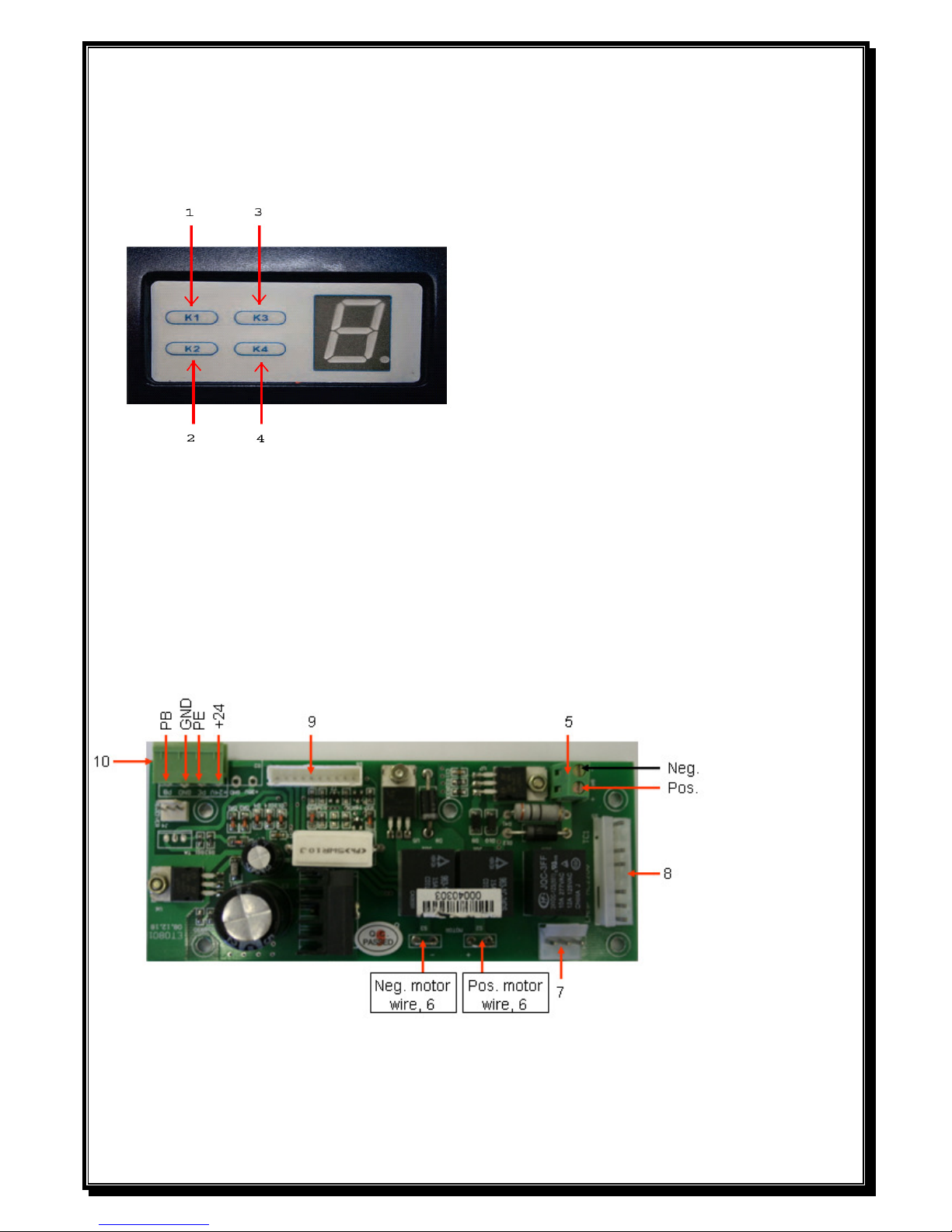
Operating Controls.
1 SET Button (K1) - Confirm set and Reversing sensitivity.
2 CODE Button (K2) - Transmitter code set.
3 UP Button (K3) - Limit mode set.
4 DOWN Button (K4) - Limit mode set
.
Circuit Board Connections.
5 Coupling for connecting the backup battery.
6 Coupling for connecting the motor.
7 Coupling for the power transformer.
8 Terminal for connecting of power input, run lamp and transformer.
9 Terminal connector to the control board.
10 Terminal connections for photo beam and push button.
PB = Push button, GND = Common & Neg., PE = Beams, +24 = 24VDC.
 Loading...