

Page 1
1
Base plate-mounting instructions
E-EEEE
DTS 512/624
SLIDING GATE MOTOR
INSTALLATION MANUAL
DTS SECURITY
P.O.BOX 3399
EDENVALE
1610
TELEPHONE 086 1000 387
Spartan +2711 392 5540 (H/O)
Pretoria +2712 548 2336
Alberton +2711 907 8846
www.dtssecurity.co.za
Page 2
2
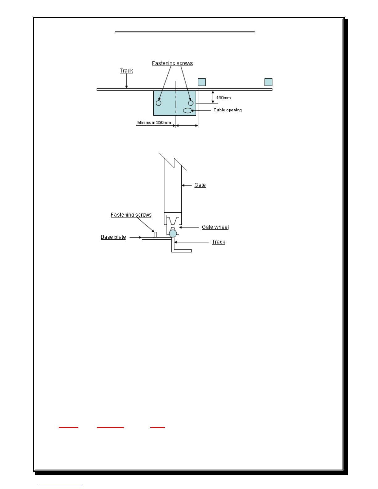
BASE PLATE MOUNTING INSTRUCTIONS
1. Assemble base plate by fastening M10x30 Hex set screws into base plate from under
the base plate up and tightening into position.
2. Mount base plate with bolts 160mm from the centre of the gate track and centre of base plate a
minimum of 250mm away from the gate opening.
3. Secure the base plate to the gate track by welding the base plate directly to the gate track. (Ensuring
a distance of 160mm from centre of gate track to centre of fastening screws).
4. Fit all required cabling through hole provided in base plate.
5. Support the back of the base plate with 40x40x3 angle iron (not provided) or similar off cut steel
knocked approximately 300 to 400mm into the ground.
6. Fill area below and around the base plate with approximately 300x400x300 concrete to ensure that
the motor will be secure.
7. NOTE – For SAFETY reasons, ALL motors should be fitted with a set of IR beams.
Page 3
3
Gearbox mounting instructions
1. Fit gearbox over mounting bolts protruding from base plate.
2. Slide gate fully open and closed, insuring pinion gear has approximately 5mm clearance to gate at
all times.
3. Fasten gearbox down firmly to base plate using M10 washers and nuts.
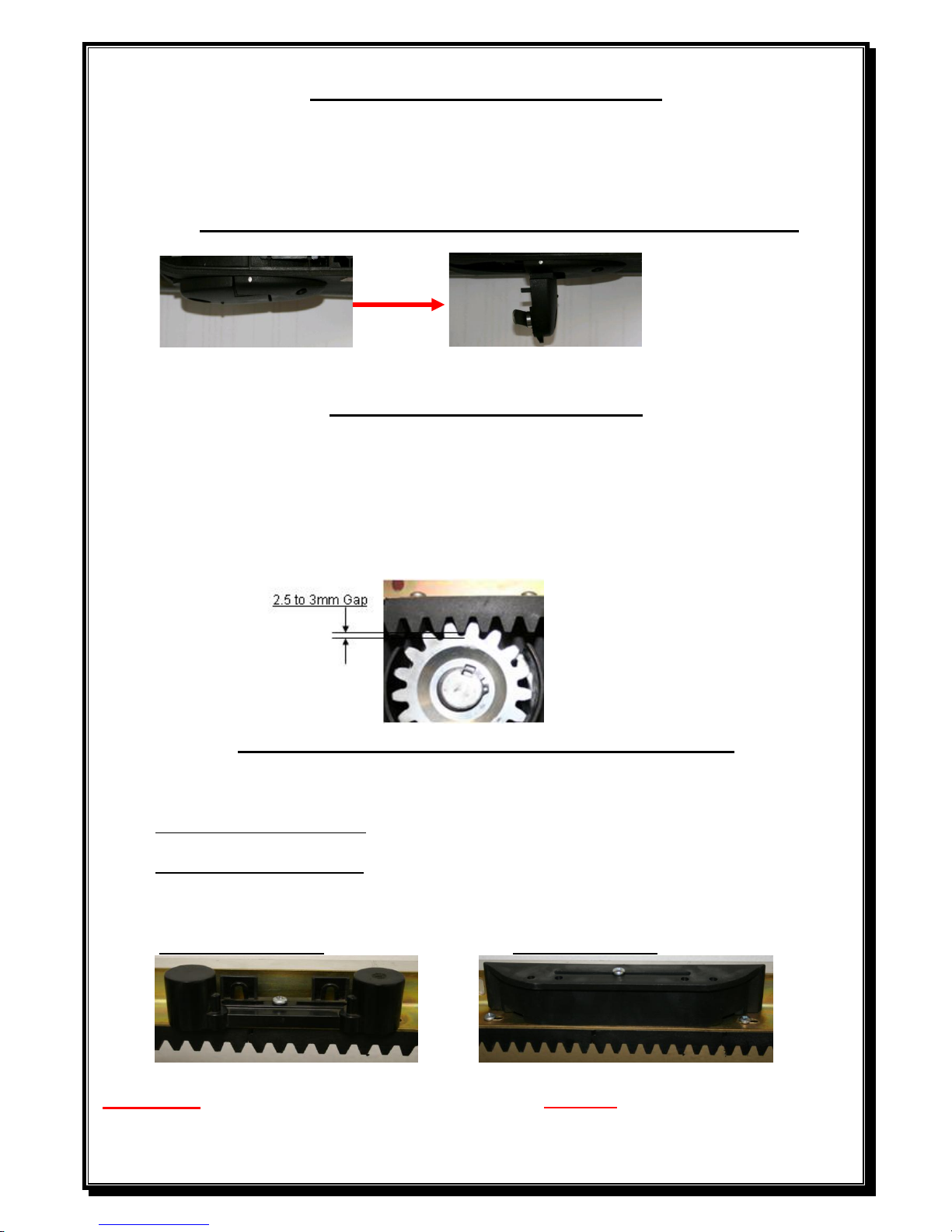
How to override the gate motor for manual operation
1. Unlock and open the override lever on the gearbox.
2. The gate can now be opened and closed manually.
Rack mounting instructions
1. Unlock and open manual override lever fully to disengage gearbox. (See above).
2. Using a 2.5 to 3mm spacer between the pinion gear and the rack, mount the rack
using Tek screws No12x20 (not provided) and screw the rack to the gate starting
from the tail of the gate and ensuring that the rack is mounted level.
(A 2.5 to 3mm spacer can also be put between motor and base plate when fitting rack. This must be
removed once the rack is in place).
NB: Ensure that one of the screws attaching the nylon rack to the angle is in line with the
read switch or limit switch spring when the gate is fully closed and open position.
Limit switch actuator mounting instructions
1. Remove the screw attaching the nylon rack to the angle that is closest to the position of the reed
switch or the spring on the motor when the gate is in the close and open position.
2. Fit limit switch actuators with screws provided onto the nylon rack.
3. Setting the gate close actuator – Close the gate with approximately 10-20mm gap between gate and
close stopper. Now move the actuator until the close LED lights up. Fasten the actuator.
4. Setting the gate open actuator – Open the gate with approximately 10-20mm gap between gate and
open stopper. Now move the actuator until the open LED lights up. Fasten the actuator.
5. (The gate must never bump against the close or open end stoppers).
Magnetic limit actuator Spring limit actuator
Important: For safety reasons, a solid stop must be fitted at both ends of the gate to prevent the gate
from moving past its full open or close position.
Page 4
4
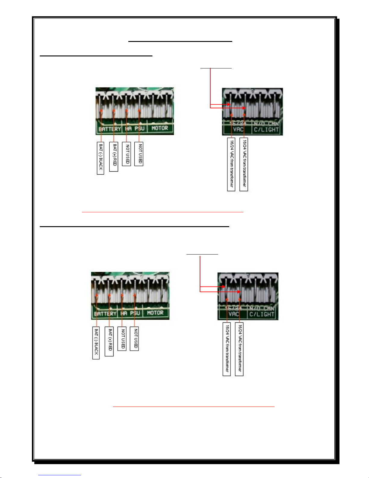
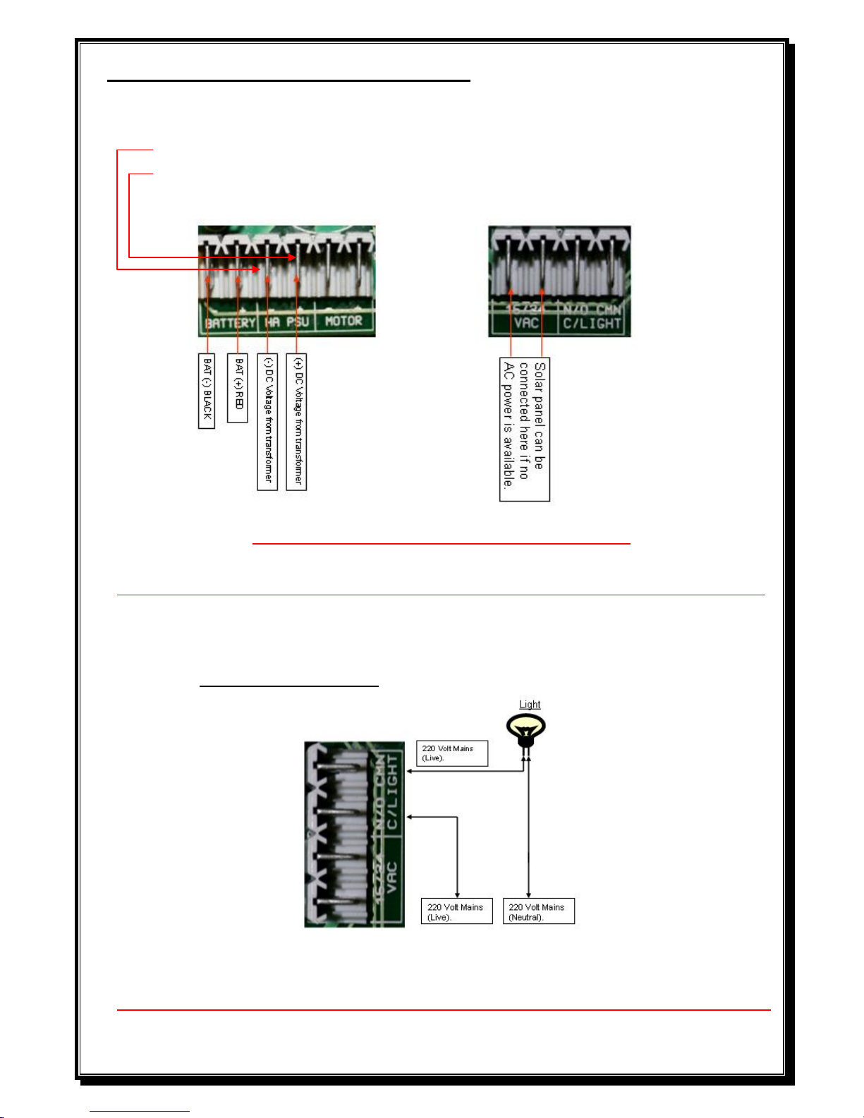
POWER CONNECTIONS
Low voltage Plug in transformer.
Connect 512/16volt or 624/24volt AC from transformer to 16/24V AC connectors on controller card.
DO NOT CONNECT 220V DIRECTLY TO PCB
Low voltage (OBT) (25 VA) transformer – 220V at gate. (DTS512 has a 500m/Amp fuse)
Connect 220V AC to input side of 512/16volt or 624/24volt AC transformer (black & brown wires), or to
NEL (Neutral/Earth/ Live) connector on side of transformer, then connect the output wires (red) to
16/24V AC connectors on controller card.
DO NOT CONNECT 220V DIRECTLY TO PCB
WHEN 220V IS USED AT GATE MOTOR, A SEPARATE DOUBLE POLE ISOLATOR MUST
BE FITTED WITHIN 1METER FROM THE MOTOR.
Page 5
5
High access power supply unit – 220V at gate. (DTS512, 220VA has a 2 Amp fuse and the
DTS624, 120VA has a 1.5 Amp fuse)
Connect 220V AC to LEN (Live/Earth/Neutral) connector on side of power supply unit.
Black lead from power supply unit gets connected to – ( neg.) PSU connection on PCB.
Red lead from power supply unit gets connected to + ( pos.) PSU connection on PCB.
DO NOT CONNECT 220V DIRECTLY TO PCB
DO NOT USE POWER SUPPLY UNIT (PSU) AND LOW VOLTAGE TRANSFORMER (16V AC) TOGETHER.
IF 220V IS USED AT GATE MOTOR, A SEPARATE DOUBLE POLE ISOLATOR MUST
BE FITTED WITHIN 1Meter FROM MOTOR.
COURTESY LIGHT OUTPUT (Will stay on for 3 minutes after a trigger is received)
(If this facility is not being used, it can then be utilized as a tamper alarm facility, see page 10).
DO NOT CONNECT 220V DIRECTLY TO PCB UNDER ANY CIRCUMSTANCES.
Page 6

6
DO ALL RUNTIME (Calibrating) AND TRANSMITTER PROGRAMMING BEFORE CONNECTING ANY
ADDITIONAL INPUTS SUCH AS, –INTERCOM, EXTERNAL RECEIVERS, BEAMS, ETC.
Diagram to connect IR Beams to PCB (Beam pins not bridged, The pins are next
to the BT/SET button)
With the beam pins bridged, the S/Beam N/O must be connected to N/C on the RX (Receiver)
Note: If sentry beams are fitted, then S/BEAM, N/O on the PCB must be connected to N/C on the RX
with the pins not bridged and N/O if the pins are bridged.
(Please note that the 12V OUT on the 512 PCB’s is an unregulated voltage up to 22Volt DC on PCB’s
up to S/N 01622836).
(PCB’s from S/N 01622837 onwards, the 12V OUT will be regulated to 12Volt DC for 512 & 624).
NOTE- IR beams must be fitted if a DTS624 motor is installed.
Dipswitch selections to activate a function.
Dipswitch 1 – Programming.
2 – Motor direction. (This can only be changed before programming or if neither limit
switches are activated).
3 – Auto close.
4 – Condominium mode.
5 – P.I.R.A.C. mode
6 – Slow down distance change
Dipswitch selection for programming. (With dipswitch 1 ON)
Dipswitch 3 – Auto close. (Infra red beams must be fitted if auto close is activated).
Dipswitch 4 – Pedestrian (Open distance and auto close time).
DO NOT CONNECT 220V DIRECTLY TO PCB
Page 7

7
PROGRAMMING
1 – Run Time (Calibrating) Setup (With total power up, AC and DC, on PCB)
Unlock and open the override lever on the gearbox.
Open the gate manually approximately 1metre.
Close and lock the override lever on the gearbox. (PCB should beep 1-5 beeps pending on load pot setting).
Pull the gate in any direction until the gear locks in.
With all dipswitches OFF (excluding dipswitch 2 depending on motor direction), press &
release the BT/SET button.
Gate will close, open and close again and stop on close limit. (Motor speed can be increased
during programming cycle by pushing and holding down the BT/SET button, but
release the button approximately 500mm before the close and open position). The final
closing cycle of programming will automatically run at normal speed.
Control card will beep twice to confirm end of program run time (calibrating) setup.
Please remove the AC jumper at this stage.
NOTE: 1) If gate opens first, dipswitch number 2 is wrongly selected.
2) Gate will automatically calibrate every time the power is restored after a
total power failure, irrespective of present dipswitch selection.
3) The controller will drive the gate approximately 6mm past the closed limit
activation position. Allowance must be made for this when setting the limit
actuators.
2 – Auto close (Default 10 seconds) (Infra red beams must be fitted if auto close is activated).
Switch Dipswitch 1 and 3 on.
Press & hold BT/SET button.
PCB will Beep (1 Beep = 1 Sec of auto close time) (Maximum 180 seconds).
Release BT/SET button at required auto close time.
Switch Dipswitch 1 and 3 off.
Switch Dipswitch 3 back on to activate the auto close.
3 – Pedestrian Opening (Default 1 meter / 10 seconds auto close)
Switch Dipswitch 1 and 4 on.
Gate must be in the closed position.
Press & Release BT/SET Button.
Gate will open.
Press & release BT/SET button to stop gate at required pedestrian opening distance.
Press & Hold BT/SET button to program auto close time required.
Control card will Beep (1 Beep = 1 Sec of auto close time) (Maximum 120 seconds).
Release BT/SET button at required pedestrian auto close time.
Switch Dipswitch 1 and 4 off.
Gate will close again.
Do not switch dipswitch number 4 back on for activating of pedestrian as this is a
preprogrammed function.
To reset factory defaults.
Remove all power from the PCB. Hold down the BT/SET button and re-connect the AC power,
with AC power now on, release BT/SET button. PCB will give one 2 second long beep followed
by 1-5 beeps, depending on load setting on pot, as acknowledgement.
Page 8

8
Load setting
To adjust the load, turn the provided load pot to determine the load setting (Minimum, anticlockwise & Maximum,
clockwise). The control card will beep, 1 minimum to 5 maximum beeps on next trigger before movement.
ON BOARD RECEIVER PROGRAMMING
The onboard receiver is designed to work with most rolling code transmitters.
(The override lever must be closed for programming transmitters).
The button used for BT LRN CANNOT be used for PD LRN and vice versa.
To individually erase transmitters:
To erase a button from the receiver, in case of incorrect programming i.e. blue button should be for BT LRN
and not PD LRN. Simply push and hold the BT LRN button for 5 seconds, the board will give 1 beep. Release the BT LRN
button. Then push and release the TX button you want to erase, the PCB will beep twice as confirmation. The TX is erased
and can be learned into correct input.
To master erase:
Push and hold the BT LRN button, after 5 seconds the board will give 1 x 1 second beep. Keep holding for another
5 – 10 seconds then the board will give 1 x 2 second beep (Older version PCB’s will give 2 beeps). Release BT
LRN button. The green receiver (RX) led will also flash 5 times indicating all transmitters erased.
Note: When programming TX no.32, the PCB will give 1x 1.5second beep after pressing and releasing the BT
LRN button indicating, Receiver (RX) is full.
The RX will abort programming automatically.
A TX must then be deleted before a next TX can be programmed to the RX.
If a transmitter is already programmed, the RX LED will go off with no beep on the 1st press from the TX.
PROGRAMMING A
TRANSMITTER (TX) FOR FULL
OPEN OPERATION – BT LRN
(Version 1.3)
PROGRAMMING A
TRANSMITTER FOR PEDESTRIAN
OPERATION – PD LRN
(Version 1.3)
1. Push the BT LRN button, the
RX led will go on.
2. Push the required button on the
transmitter, at arms length from
PCB once, the Rx led will flash.
Press the same button again,
and the PCB will emit 3 beeps
for a full Keelog transmitter or
2 beeps for other transmitters.
3. Repeat Step 1 and 2 for
additional transmitters. Up to 31
transmitters can be programmed
as a joint combination between
BT LRN & PD LRN.
1. Push the PD LRN button, the
RX led will go on.
2. Push the required button on the
transmitter, at arms length from
PCB once, the Rx led will flash.
Press the same button again, and the
PCB will emit 3 beeps for a full
Keelog transmitter or 2 beeps for
other transmitters.
3. Repeat Step 1 and 2 for additional
transmitters. Up to 31 transmitters
can be programmed as a joint
combination between BT LRN &
PD LRN.
Page 9

9
ELECTRONICS
FEATURES:
1. Standard mode.
2. Easy motor direction change.
3. Auto close facility. (Infra red beams must be fitted if auto close is activated).
3a. Party mode. (Auto close override)
4. Condominium / Free exit loop facility.
5. P.I.R.A.C. (Passive Infra Red Access Control) facility.
6. Slowdown (Ramp down) facility.
7. Tamper alarm facility. (Only available from Version 1.8 software).
8. Anti highjack. (Only available from Version 1.9 software).
9. Holiday Lockout.
1. Standard Mode. (No function selected).
When the gate is activated it will open and can be stopped in mid cycle by pressing the
transmitter or manual push button. Pressing the transmitter or push button can reverse the
gate. In standard mode the gate will remain on its open limit until it is triggered to close.
If main power fails, the motor will still operate until battery reaches 9.5/19 volt. (9.5 V for
512 & 19 V for 624 motors). Gate will then remain close (Open if condominium mode is
selected). Change to manual by overriding the motor by the override lever. When the main
power comes on again, lock in the override lever and the motor will function as normal.
2. Easy motor direction change. (Dipswitch 2).
By selecting the dipswitch, the motor direction and the limit wires are changed
automatically. Dipswitch ON, gate closes to the right. Dipswitch OFF, gate closes to the left.
3. Auto close. (Dipswitch 3 ON). (Infra red beams must be fitted if auto close is activated).
When Auto close is activated and the Gate opens to the open limit, the gate will wait the
pre-programmed time before automatically closing. If the gate is triggered while the gate is
in its closing cycle it will stop and reopen.
If the transmitter or manual push button is pressed while the gate is in its opening cycle, the
gate will stop and close after the preprogrammed auto close time (from any position, not
only from the open limit)
3a. Party mode. To override the auto close, wait till the gate reaches its open limit then
press & hold the transmitter or manual push button for approximately 6 sec. (The control
card will give 1 long beep to confirm the override) To reactivate the auto close, press the
transmitter or manual push button.
4. Condominium/free exit loop (Dipswitch 4 ON)
When condominium/free exit loop is activated on the unit, the unit will not respond to any
transmitter or manual push button while in its opening cycle or open position. When the
gate is on the open limit the unit will automatically wait the pre-programmed auto close
time and then close (even if auto close function is not selected i.e. dipswitch 3 is off).When
the gate is in its closing cycle and the transmitter or manual push button is pressed the gate
will stop and open. Auto close cannot be over ridden in condominium mode. (No party
mode). If main power fails, the motor will still operate until battery reaches 9.5/19 volt.
(9.5 volt for 512 and 19 volt for 624 motors). Gate will then remain open.
Change to manual by overriding the motor by the override lever. When the main power
comes on again, lock in the override lever and the motor will function as normal.
5. P.I.R.A.C (Passive Infra Red Access Control) (Dipswitch 5 On)
With P.I.R.A.C mode activated, if the gate is its opening cycle and the IR beam is activated
the gate will stop and close immediately after the IR beam is clear. This will happen even if
auto close has not been selected.
(Be aware of this factor should a trailer be in tow!!!!)
Page 10

10
6. Slowdown (Dipswitch 6)
With dipswitch selected ON, the gate will have a long close and open controlled slow down
distance of 800mm and with the dipswitch OFF, the close and open controlled slow down
distance will remain the same unless programmed to a shorter distance.
(Contact the supplier for instructions to this programming).
NOTE – (Long controlled slow down distance is recommended if the limit is continuously
being overrun).
7. Tamper Alarm Facility (Only available from Version 1.8 software and later)
If the courtesy light feature is not used then the courtesy light relay can be re-configured as
a general Tamper alarm output. Re-configuration is achieved with the following procedure.
A) Latching tamper (Siren – N/O relay contact) output.
Make note of the option dip switch settings, then remove the power (AC and DC) from the
control PCB and open the gearbox release. Switch all dip switches to the OFF position, then
select dipswitch 1 and 6 to the ON position. Reconnect the power to the PCB and after
approximately 2 seconds, select dipswitch 1 and 6 back to OFF position.
The setting is confirmed by 1 to 5 beeps (depending on where the load pot setting is).
Select the dipswitch settings back as per your notes. Close the gearbox release and perform the
normal power up calibration routine.
B) Impulse tamper (Alarm – N/O relay contact) output. Repeat section A) using dipswitch 1 and 5.
C) Normal Courtesy light mode. (No Tamper alarm). Repeat section A) using only dipswitch 1.
D) Continuous alarm output. Repeat section A) using dipswitch 1 and 4.
The tamper alarm will automatically arm itself when the gate is in the closed position and will trigger
the alarm relay if the gate is moved or forced off the closed limit switch without a valid trigger.
If latching mode is configured, the relay will switch every 3 minutes until the alarm is restored.
If impulse mode is configured, the relay will trigger only once.
Any valid gate or pedestrian input trigger will cancel the tamper alarm which will automatically re arm once the gate is again in the close position.
The alarm can also be disabled for maintenance by opening the gearbox release and pressing the
remote control push button (confirmed by 3 short beeps). The alarm will remain disabled until the
gearbox release is closed and the gate closed position re-confirmed.
Bridge pus h
button
contacts
Pos.
Neg.
Pos.
Neg.
Ba tt.
Po s.
Ba tt.
Ne g .
Wiring, Pulse (Alarm )Wiring, Latch (Siren)
Pu lse R e ceiver
Transm itte r
Co m . N /C
Alarm P a nel
Co m . Z o ne
Page 11

11
8. Anti-highjack (Only available from Version 1.9 software)
When the tamper alarm function is active and the gate receives a valid trigger but is obstructed
and cannot move or did not move more than 150mm, the alarm or siren will activate.
If the beams are obstructed or blocked when a trigger is received, the gate will open but will
then also sound the alarm.
9. Holiday Lock-out facility (New version PCB’s, this function must be programmed in).
To activate holiday lock-out, (the gate must be in the closed position) press and hold any
pedestrian trigger function for a period of approximately 13 seconds. After approximately
13 seconds the PCB will give one three second beep as acknowledgement that holiday lock-out
is now activated. To de-activate holiday lock-out, repeat the above process. The PCB will
in this instance give five 1 second beeps as acknowledgement de-activate.
(To activate the above, follow the alarm function procedure but utilizing dipswitch 1, 5&6).
List of audio indications and warnings.
One continuous beep - PCB is damage, replace PCB.
One 1.5 second beep - “Party mode” has been activated.
One 2 second beep - Factory defaults have been set.
One 2 second beep - Beams are incorrectly wired or faulty when programming the motor.
or Runtime was aborted for whatever reason.
One 3 second beep - Holiday lockout mode has been activated.
One 3 second beep - Gate triggered when motor is in 3 minute overload lockout.
Two 400 ms beeps - Run time programming (calibrating) has been successful.
Two 1 second beeps - Pedestrian mode was activated.
Two 2 second beeps - No AC power is present, running battery power only.
Three 200ms beeps - Battery power is too low, or
Override function is open or faulty.
Four 100ms beeps - Motor is in holiday lockout.
Four 200ms beeps - Check motor/load fuse (512/25amp or 624/10amp).
- Check motor brushes and armature.
- PCB reader not picking up Magnet on motor.
Five 1 second beeps - Holiday lockout mode has been de-activated.
Twenty 100ms beeps - Motor has stalled or overloaded, then check the following points:
1) Gate pulling force (should not exceed 512/12.5kg or 624/15kg)
2) Load pot is set too low (Turn pot completely clockwise)
3) Battery voltage under load (512/12volt or 624/24volt) (Not connected)
4) Gearbox gearwheel.
List of LED indications.
FOR SAFETY REASONS.
Infra red beams are recommended for
all gate motor installations.
- LED ON when open limit is activated. (gate open).
- LED OFF when close limit is activated. (gate closed).
- LED flashing SLOW (1 sec. on/1 sec. off) (gate is in motion).
- LED flashes 2 long/3 short continuously (gate is stopped midway).
- LED flashes fast (250ms on/250ms off) continuously. (gate in overload).
- LED flashes 3 fast flashes every 1.5 seconds. (battery low, <11/22VDC).
- LED flashes 1 slow/2 fast continuously. (NO 220 VAC power present).
Page 12

12
PCB Control card.
AC Jumper Beam option jumper for N/O or N/C beams
500 m/Amp AUX. 2 Amp AC self reset able fuse.
self reset able fuse.
For PCB identification
2 x Voltage regulators = 24V motor. (2
nd
voltage regulator will cover 12V)
1 x Voltage regulator = 12V motor. (New version will have 2 regulators fitted)
NOTE: With the infra red beam option pins not bridged the PCB operates as N/O beams.
. With the option jumper bridged the PCB operates as N/C beams. (Fail safe mode).
NB – When connecting intercoms to the control card (IT and CMN), please ensure that your intercom
trigger output is potential free (ZERO voltage). If not, a gate relay module must be fitted.
Note; 1) The 12V OUT on the 512 PCB’s is an unregulated voltage up to 22Volt DC.
(New 512 version with 2 regulators will have a regulated 12 volt AUX output)
2) The 624 H/A model will have a wire connected from battery positive to the transformer.
3) Please ensure that the auxiliaries connected to the 12 volt auxiliary output does not exceed
500 m/Amps in total. (If so, remove from aux. output and connect directly to battery)
Page 13

13
TROUBLESHOOTING
SYMPTOMS
CAUSES
ACTION
When pressing the remote
transmitter or manual push
button the gate operator will
not respond at all.
PCB responds but gate will
not open.
PCB responds by giving 4
very quick 100ms beeps but
will not open.
PCB responds by giving 4
200ms beeps but no
movement.
Charge rate drops to +-7
volt.
Transmitter battery flat.
Transmitter or manual push
button is physically damaged.
Transmitter has not been
programmed into the receiver
memory or manual push
button is not connected to the
PCB or push button.
The override reed switch in the
gear box is faulty or failing to
make connection between PCB
and read switch or the magnet
in the override door is missing.
Condominium /loop option is
not activated and the battery
has reached its low level (9.5
or 19 Volt).
Motor is in holiday lockout.
Motor/Load fuse is faulty or
motor brushes not making
contact with armature.
12 Volt aux. output of
500m/Amps have been
exceeded.
Replace transmitter battery.
Check with supplier.
Follow the receiver setup
instructions.
Check wiring between PCB
and push button.
Replace the reed switch and or
the magnet. (For short term
solution, bridge out the two
pins on the PCB were the read
switch wires should go).
Check the household main
supply, the transformer or
Power Supply Unit and all
related cabling.
Press and hold the pedestrian
remote or manual push button
connected to PD on PCB for
approximately 13 seconds until
PCB gives 5 long beeps.
Replace fuse. (Fast blow fuse).
Repair or replace (if shorter
than 7mm) motor brushes.
Remove some of the
auxiliaries. (Can connect them
to the battery directly)
Before operating, the unit
gives two long 2 second
beeps.
The primary supply has failed
and the unit is running on
battery reserve.
Check the household main
supply, the AC transformer or
DC Power Supply Unit and all
related cabling.
Page 14

14
The gate opens but will not
close.
The primary supply has failed
and the unit is running on
battery reserve with the
condominium/loop option
selected and it has reached its
low battery limit (9.5 or 19
Volt).
Safety infra-red beams are
obstructed or the beams
equipment/cabling are faulty
or incorrectly wired.
Check the household main
supply, the transformer or
PSU and all related cabling.
Clear obstruction, repair or
replace safety infra-red beams
equipment/cable, fix incorrect
wiring connections.
The gate when closing stops
and reverses or when
opening stops.
OR
Gate tries to run and the
relays kick out.
The unit is sensing an
obstruction
The infra-red beam has been
triggered.
Another trigger has been
received by the control card.
Encoder is faulty.
Clear obstruction or adjust
load sensing.
Clear obstruction.
Check with other operators on
the system.
Turn ring magnet on the motor
by hand: if no activity on the
encoder LED, contact
supplier.
Gate does not remain open.
Auto close has been activated.
Another user has triggered the
unit.
Condominium/loop has been
activated.
De-activate auto close or use
auto close override.
Check with other operators on
the system.
De-activate condominium /
loop mode.
When the beams input is
triggered, the gate stops and
reverses during opening
cycles.
P.I.R.A.C. mode has been
activated.
Gate is closing in the wrong
direction.
De-activate P.I.R.A.C. mode
Dipswitch 2 is selected
incorrectly.
Page 15

15
The unit gives two short 1
second beeps and opens
partially and stops, gives two
short 1 second beeps and
then closes.
The pedestrian (PT) mode on
the PCB is being triggered.
A transmitter code has been
programmed incorrectly into
the pedestrian (PD LRN)
function of the receiver.
Check equipment /cabling
attached to the pedestrian (PT)
on the PCB input.
Delete the transmitter and reprogram the transmitter into
the receivers (BT LRN) as per
instructions.
When gate reaches a limit
actuator, the unit does not
stop running.
Limit input wired incorrectly
(out of sync’ with the motor
direction.)
Limit switch is faulty.
Re-wire
Change limit switch or check
with supplier.
Gate motor is jumping teeth
on the rack.
Pinion to rack spacing is
incorrect.
Rack is insufficiently fastened
to gate leaf.
Debris on track
Re-align.
Re-align and correct fastening.
Clean track
Gate jams in the open or
closed position and is not
easy to manually release.
Gate opens pedestrian when
full open trigger is given.
PCB does not beep 1-5 beeps
on closing the override lever.
Gate is running too far.
Gate is running past its limit
actuator.
Gate is overloading in the
close position after it received
a pedestrian trigger.
The magnet inside the
override lever is missing.
The double green wire reed
switch inside the gearbox is
faulty.
Adjust the limit actuators until
there is a gap between gate
and stoppers of approximately
10 – 15 mm
Replace the switch, rewire
correctly or check limit spring
assembly.
Move the closing limit
actuator towards the closing
cycle approximately 10mm.
Replace the magnet.
Replace the reed switch.
(The reset pins on the PCB
can be bridged as a short term
solution).
Page 16

16
Manufacturers warranty.
All motors manufactured by DTS Security carry a 24 month factory warranty
from date of invoice. (Excluding batteries & Remote controls).
Batteries & remote controls carry a 12 months warranty.
(Remote batteries are consumables and therefore carry NO warranty)
All goods are warranted to be free from faulty components and manufacture.
Faulty goods will be repaired or replaced at the sole discretion of DTS Security
Products, free of charge.
This warranty is subject to the goods being returned to the premises of DTS
Security Products.
This warranty excludes lightening damage, insect damage and damage caused
by faulty installation.
In the event of the goods being supplied by dealer, merchant, agent or duly
appointed installer of DTS Security Products, the claim must be directed to
that supplier.
The carriage of goods is for the customer’s account.
This warranty is only valid if the correct installation and application of goods,
as laid out in the applicable documentation accompanying said goods, is
adhered to.
All warranty claims must be accompanied by the original invoice.
The liability of DTS Security Products and / or their distributors is limited as
herein set out DTS Security Products and / or their distributors will not be liable
for consequential, incident damage or injury howsoever arising.
 Loading...