

Page 1
AP1 & AP2 CURTAIN EYELET PRESS
INSTRUCTION MANUAL
Page 2

AP1 and AP2 Manual
INTRODUCTION
The AP1 and AP2 are manually operated robust presses specifically designed for setting curtain eyelets up
to a maximum internal diameter of 66mm. See below for a full list of sizes. A wide range of smaller eyelets
can also be set on the AP1 or AP2. Please ask for details.
The machine head can be supplied either bench mounted or as a head only. If required a bench can be
purchased retrospectively.
The rack and pinion assembly should be lubricated with thick grease such as Delta 2EP. Thin grease or oil
will run down the spindle and onto the material to be eyeleted.
Health and Safety Note
The AP1 and AP2 machines are operated using only manual effort and are not covered by the Supply of
Machinery Regulations.
Do’s & Don’t’s
Do keep the machine head bolted to a stable level surface. Adjust the feet on the bench if necessary.
Do lubricate the rack and pinion with thick grease (Delta 2EP or similar).
Don’t use the cutting tools to cut metal or anything other than fabric. This can result in chips on the
cutting edge.
Don’t put limbs, hair, jewellery or other loose or trailing items of clothing between the closing or cutting
tools.
Curtain Eyelet Sizes
Eyelet Reference Internal Diameter
VL100 25mm
VL130 30mm
VL150 40mm
VL170 50mm
VL200 66mm
Page 2 of 15 v1.4 DTP Supplies
Page 3
AP1 and AP2 Manual
Loaded)
INITIAL SETUP
If the bench mounted variant of the machine has been ordered, the head will already be mounted. If the
head only has been ordered it is necessary to mount the head on to a sturdy stable work surface using the
bolts, washers and nuts supplied.
When the machine is removed from the packaging the handle will be enclosed separately. Before adjusting
the machine ensure that the handle is inserted into the pinion as shown and that it is pointing backwards at
the lowest position. Secure the handle using the winged bolt and split pin as shown in the quick reference
guide (page 8).
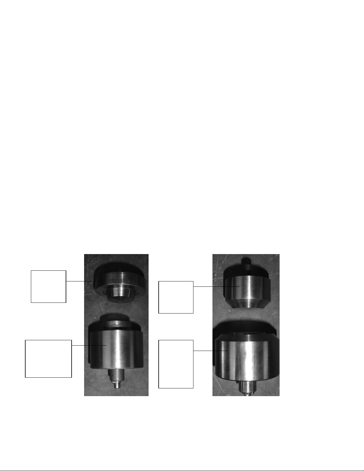
There will be one or more sets of tools supplied with the machine, rolling tools and/or cutting tools. Each
rolling set consists of two parts, a face die with a protruding spring loaded centre and a rolling die which is
solid. The size of eyelet that the tool is designed to set is printed on the side of each part, ensure that you
have a matching set. The face die should be inserted into the bottom die holder and it is then secured by
tightening the grub screw at the front of the base plate. The rolling die is inserted into the top die holder
and is secured using the grub screw at the front of the rack.
The cutting sets consist of two parts, a bottom die with a flush spring loaded centre and solid top die. The
size of hole that the tool is designed to cut is printed on the side of each part, ensure that you have a
matching set. The bottom die should be inserted into the bottom die holder and it is then secured by
tightening the grub screw at the front of the base plate. The top die is inserted into the top die holder and is
secured using the grub screw at the front of the rack.
Top
Closing
Die
Top
Cutting
Die
Bottom
Closing Die
(Spring
Bottom
Cutting
Die
(Spring
Loaded)
Page 3 of 15 v1.4 DTP Supplies
Page 4

AP1 and AP2 Manual
ADJUSTING THE CLOSING PRESSURE
1. Close the dies by turning the handle from the rear through 180o to the front. Maximum force is
exerted when the handle is at 90o to the machine head. The handle should stop in this position
when the closing pressure is correctly set.
2. The gap between the tools should be approximately the same thickness as the material the
eyelet is to be set into.
Material
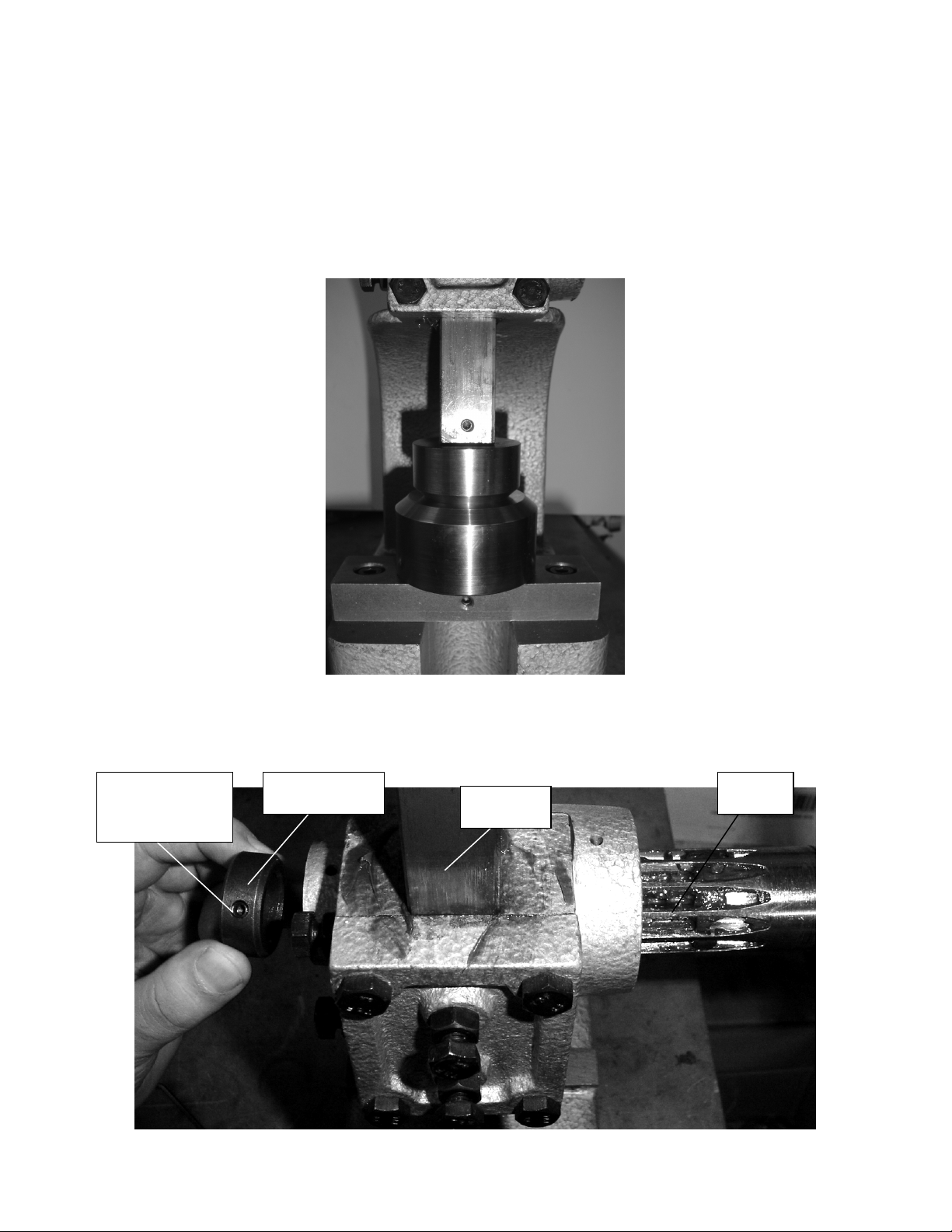
3. Adjustment of the die gap is achieved by removing the handle and releasing the collar by
loosening the grub screw shown. Remove the collar and pull the pinion out to disengage it from
the rack. The rack can now be moved by hand from the top. Set the gap to the approximate
thickness of the material.
Grub Screw
Collar
Rack
Pinion
Secures Collar
4. Once the die gap is set, test the setting by inserting an eyelet into the material by following the
instructions below. Perform further adjustments until the die gap is correctly set.
Page 4 of 15 v1.4 DTP Supplies
Page 5
AP1 and AP2 Manual
ADJUSTING THE DIE CUTTING PRESSURE
1. Close the dies by turning the handle from the rear through 180o to the front. Maximum force is
exerted when the handle is at 90o to the machine head. The handle should stop in this position
when the cutting pressure is correctly set.
2. There should be no gap between the tools.
3. Adjustment of the die gap is achieved by removing the handle and releasing the collar by
Grub Screw
Secures Collar
loosening the grub screw shown. Remove the collar and pull the pinion out to disengage it from
the rack. The rack can now be moved by hand from the top. The two die parts should meet.
Collar
Pinion
Rack
Page 5 of 15 v1.4 DTP Supplies
Page 6

AP1 and AP2 Manual
4. Once the die gap is set, test the setting by attempting top cut a hole in the material. Place the
material between the tools and pull the handle down until it will travel no further. A ‘crisp’
shearing sound should be heard. When the material is removed there should be a hole in the
material. If the hole is not cut cleanly perform further downward adjustments until the die gap is
correctly set.
Page 6 of 15 v1.4 DTP Supplies
Page 7

AP1 and AP2 Manual
INSERTING AN EYELET WITH SEPARATE CUTTING & CLOSING TOOLS
1. Insert the cutting tools into the machine as described on page 5.
2. Place the material between the tools where the eyelet is to be inserted and pull the handle
forward and down to its lowest position to cut the hole.
3. Remove the cutting tools and replace with the closing tools. Return the handle to the rear of the
casting and remove the material from between the tools.
4. Place the eyelet onto the spring loaded centre of the bottom die as shown.
5. Place the hole in the material over the eyelet barrel.
Eyelet
Page 7 of 15 v1.4 DTP Supplies
Page 8

AP1 and AP2 Manual
6. Place the washer with the ‘teeth’ pointing downward into the material over the eyelet barrel.
Washer with ‘teeth’
pointing down
7. Pull the handle forward and down until it is in its lowest position.
8. Return the handle to the rear of the casting and remove the material from between the tools.
Eyelet & Washer Set
(Washer Side)
There should be little or no gap between the eyelet, washer and material and the eyelet and washer should
not ‘spin’ once inserted in the material. If the eyelet does spin the die gap should be reduced following the
instructions above.
Page 8 of 15 v1.4 DTP Supplies
Page 9

AP1 and AP2 Manual
SETTING THE VL150 EYELET USING A COMBINATION TOOL
1. The combination tool is comprised of two parts. The parts are illustrated in the photographs below. Insert the
top die into the machine rack and the bottom die into the machine base plate.
2. Once the tool is in the machine and the machine has been adjusted for height and alignment place the
washer with the piercings pointing upward onto the bottom die.
Page 9 of 15 v1.4 DTP Supplies
Page 10

AP1 and AP2 Manual
3. Place the material over the bottom die where the hole is to be cutter. Ensure that the material is placed
carefully to avoid cutting the hole in the wrong place. The centre of the hole will be at the centre of the
bottom die.
4. Rotate the hand lever on the machine forward to cut the hole. A reasonable amount of pressure is required
to produce a clean cut.
Page 10 of 15 v1.4 DTP Supplies
Page 11

AP1 and AP2 Manual
5. Rotate the hand lever backward and leave the material in situ.
6. Place the eyelet with the flange (widest part) upward through the hole in the material so that the eyelet
barrel is over the bottom die.
Page 11 of 15 v1.4 DTP Supplies
Page 12

AP1 and AP2 Manual
7. Rotate the hand lever forward to set the eyelet. A reasonable amount of pressure is required to set the
eyelet. If the eyelet does not set fully first time it can be put back over the bottom die for this operation to be
repeated.
8. Rotate the hand lever backward and remove the eyelet from the bottom die. The rear of the eyelet should be
rolled as shown in the photograph below and should be tight on the material.
Page 12 of 15 v1.4 DTP Supplies
Page 13
AP1 and AP2 Manual
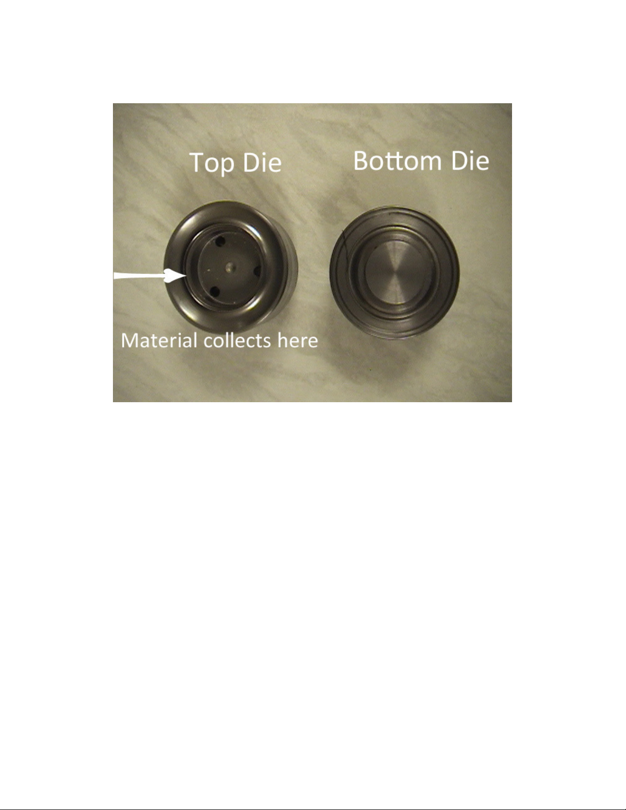
9. After approximately three to four hole cutting operations, depending on material thickness, the material
slugs held in the hollow of the top die have to be cleared. This can be done whilst the top die is held in the
machine. Alternatively it can be easier remove the top die to perform this operation.
Page 13 of 15 v1.4 DTP Supplies
Page 14

AP1 and AP2 Manual
Guide f
or Pitching
Screws to attach base plate
USING THE MEASURING GUIDE
The measuring guide illustrated below is available either with the machine or as an optional extra to be
added at a later date.
1. The guide is attached to the side of the base plate using the screws provided.
2. The back stop on the guide can be moved backward or forward to set the position of the eyelet
from the top edge of the material.
3. The pitching point can be moved left and right to adjust the position of the eyelet centers. Once
the first hole has been cut place the hole over the pitching point to position the next hole.
4. Should you wish to use the guide from the opposite side. Remove the bottom die and base plate
using the allen keys provided and turn the base plate through 180o. Re-attach the base plate,
insert the bottom die and attach the guide.
Page 14 of 15 v1.4 DTP Supplies
Point
Backstop
Pitching Point
Base plate
under here.
Page 15

AP1 and AP2 Manual
QUICK REFERENCE GUIDE
Setting Handle
Keep Rack Clean &
Lubricate Occasionally
Collar Secures
Grub Screw
Secures Top Die
Pinion
Wing Bolt Secures
Handle
Split Pin Prevents
Handle Pulling
Through
Base Plate
Grub Screw
Secures
Bottom Die
Page 15 of 15 v1.4 DTP Supplies
 Loading...