

SLIM II photocell
MOUNTING INSTRUCTION
1. Principle of operation
Photocell includes transmitter and receiver (fig.1). The transmitter emit a coded Irfrared (IR) signal
invisible to the naked eye. Obstacle appearance (e.g. car) on photocell working area produces a
detection signal on receiver output. Receiver has NC and NO type output contacts, the circuit is protected
by additional relay. Photocell is destined to work in gate automation system as external element.
2. Technical data.
4 Guaranteed range 1-15 m
4 Angle of view adjustment horizontally 200° in receiver and transmitter
4 Power suplly of transmitter and receiver 12-24V AC/DC
(synchronization option requires AC supply)
4 Current consumption of transmitter max. 25 mA
4 Current consumption of receiver max. 25 mA
4 Working temperature (min. / max.) -20°C / +55°C
4 Outside dimensions (WxDxH) 35 x 30 x 110 mm
4 Mounting surface mounted splash proof case - Ip54
4 Output contacts NO and NC
v.1.4
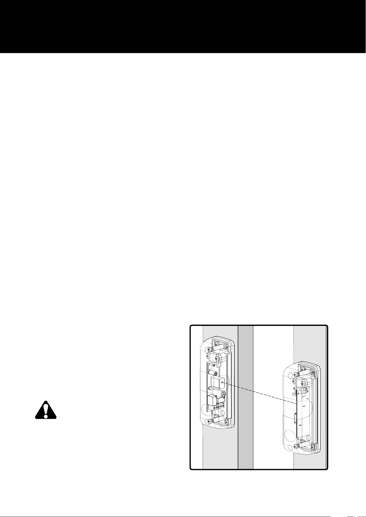
3. Photocell mounting.
For proper funcionality photocell must be mounted 40-60 cm off the ground, receiver and
transmitter distance not less than 1 m. Photocell has angle of view adjustment in receiver and transmitter.
Coaxial mounting is unnecessary. Give consideration to electric boards maximum angle of rotation inside
transmitter and receiver enclosure. Because of photosensitive elements it is recommended to mount
receiver on less sun exposure side. Both receiver and transmitter must be mounted vertically. Terminal
blocks and humidity carrying openings should be in the bottom part of enclosure. Proper receiver and
transmitter adjustment is facilitated by receiver's green diode RX. RX diode lights when transmitter ray
reaches receiver. Both enclosures should be mounted by 2 (diagonal mounting) or 4 screws available in
set.
Transmitter
TX
max 15 m
min 1m
Do not mount mirrors or reflection
screens in photocell's working area, if
possible mount the receiver on the less
exposed to the sun side, do not mount the photocell
receiver in a location exposed to strong light source
of stray light, especially fluorescent light, it can
inter f e r e t h e b a r rier. B e w are of o p tical
receiver/tra nsmit ter elements soiling wh ile
mounting.
Receiver
RX
Fig.1. Exemplary receiver - transmitter location

SLIM II photocell
MOUNTING INSTRUCTION
4. Photocell connection
Photocell cooporates with most of gate controllers available on market.
It is recommended to do electrical installation and photocell mounting by qualified person.
Connect photocell according to Fig. 3 scheme
and description below.
Without synchronization function
4Make sure the ZW jumper on the transmitter and
receiver are mounted.
4Connect the power supply 12-24V AC/DC to
photocell transmitter and receiver. POWER LEDs
on the transmitter and the receiver, and RX LED on
the receiver should light up.
4If you use the AC power supply to power the
transmitter and receiver use the same phase (with
one power supply)
4Connect the output signal of photocell (usually NC
and C) to proper inputs on the control unit. Pay
particular attention to the type of control (NC or NO)
required in the control panel. The standard solution
for gate automation is to work with optical sensors in
the NC.
2
1
With the use of synchronization function
Using synchronization function, you can
install two pairs of photocells with the
overlapping area of the optical range.
To use the synchronization function, you
must cut the ZW jumper in photocell transmitter and
receiver, and supply them with alternating voltage
(12-24V AC).
Connect the same wire to the terminal marked "1" on
the transmitter and the receiver of the first pair of
photocells. If swap wires only on the transmitter side
or only on the receiver side, will result in no action of
photocells. The second pair of photocells must be
powered by the same phase as the first, but wires in
the supply line of transmitter and receiver must be
swap. (the power wire connected to the terminal
marked "1" in the first pair of photocells, must be
swap with the next wire in the second pair of
photocells).
o
200
18 mm
93 mm
8 mm
USE THIS FIGURE AS A TEMPLATE
Description:
1. splash-proof cover
2. hole for wires =7mm
Fig. 2 Distance of the mounting holes
on a scale of 1:1, with the assembly drawing.

Power supply: 12-24V AC/DC Working Temp.: -20°C / +55°C
Current consumption: max. 25mA Cover IP: 54
Range: 1 - 15m Dimensions: 35x30x110mm
In case of problems with identifying the AC power cable, you can use the following
procedure, in order to connect two pairs of photocells located in one area of the optical range:
4make sure the jumper labeled 'ZW' in transmitters and receivers of both pairs of photocells are cut
(open),
4Connect the power supply 12-24V AC (alternating) to the transmitter and the receiver of the first pair of
photocells. POWER diode should light on the transmitter and receiver, as well as the RX diode on the
receiver. If the RX diode is off, swap wire only on the transmitter side or only on the receiver side. If the
RX diode still not light, it means that the receiver can not "see" the ray of the transmitter - adjust the
position of the transmitter or receiver and, if necessary, repeat this step.
4supply power to the receiver of the second pair of photocells. The result should be to light only the
POWER diode on the receiver. RX diode should remain off (meaning no reaction of the receiver of the
second pair of photocells on the ray from the transmitter of the first pair of photocells). If the RX diode is
light, swap the receiver supply wire.
4Supply power to the transmitter of the second pair of photocells. The POWER diode on the transmitter
should light, the RX diode on the receiver of second pair of photocells should also light up. If the RX diode
is off, swap the transmitter supply wire.
4Connect the photocell receiver signal terminals (usually NC and C) to the proper input of the control
unit. Pay particular attention to the type of control (NC or NO) required in the control panel. The standard
solution for gate automation is the work in optical sensors in the NC.
5. Receiving tests.
After photocell connection is done, it is recommended to check receiver (RX) reaction on Irfarared
signal breaks. Gate automation systems must be tested conformity to EN 12445 standard.
Photocell test:
4Supply power to receiver only and check if RX diode out.
4Supply power to transmitter and check if RX diode light.
4Displace roller of 5 cm diameter and 30 cm length, to break perpendiculary optical axis between
receiver and transmitter. First in the vacinity of transmitter TX, next in the vacinity of receiver RX,
next in the middle of distance between them. In all cases photocell should switch from standby to
alarm mode, which is signalized by RX diode wane.
6. Warranty.
DTM System checks all the devices before shipping. The warranty time is 24 months from the
selling date. This time is counted according to the warranty label. The manufacturer will fix all the
problems which come because of his fault. Non functionaing device should be delivered back to the
distributor with short problem description. The cost of mount/dismount is covered by user. The warranty
do not cover: batteries in the remotes, faults caused by improper usage, user self reairs and adaptations,
lightning strikes, over voltages or short circuits in the mains supply. Appropriate legal acts regulates
details of the warranty.
The intention of the WEEE Directive (Directive 2002/96/EC on waste electrical and electronic
equipment) is to reduce the amount of hazardous substances in waste.
The underlying purpose is to promote the avoidance, recovery and risk-free disposal of waste.
DTM System spółka z ograniczoną odpowiedzialnością spółka komandytowa
ul. Brzeska 7, 85-145 Bydgoszcz
tel./fax. (52) 340-15-83, 340-15-84
www.dtm.pl, dtm@dtm.pl

Transmitter - TX
jumper
**
LO POWER
terminal
numer “1”
*jumper ZW
ZW
1
1
AC/DC
12-24V
transmitter - TX
1
1
AC/DC
12-24V
Pair 2
Receiver - RX
*jumper ZW
terminal
**
LO POWER
Sygnalization:
POWER
ZW
terminal
terminal
no. “1”
ZW
no. “1”
1
*jumper ZW
1
receiver - RX
1
1
NC C NO
terminal description
* wires swap in the supply line
between two pair of photocell
Transmitter - TX
Pair 1
CONNECTION SCHEME
ZW
1
Receiver - RX
RX
POWER
Terminal
sygnalization:
For the synchronation function, use only the power supply voltage alternating current (AC) and cut the ZW jumper in transmitter and receiver of both pairs of photocells.
*
To do this, cut the LO POWER jumper in transmitter.
When using photocells in a place where interfere due to reflections from walls or other items reduce the power of the transmitter.
Swap wires in the supply line in one pair of photocell.
**
Control board
*jumper ZW
numer “1”
*
1
CONTROL SIGNAL 2
CONTROL SIGNAL 1
photocell 2 (NC)
signal INPUT 2
photocell 1 (NC)
singal INPUT 1
12-24V AC/DC
accessories supply OUTPUT
POWER SUPPLY, polarity irrelevant
Fig. 3 Wiring diagram to connect the photocell without synchronization (1 pair)
and using the synchronization function (two pairs of photocells).
 Loading...