

Page 1

REMOTE CONTROL
SYSTEM
REMOTE CONTROL
SYSTEM
MADE IN
POLAND
Receiver Rival 434
Operating manual
Page 2

Page 3

The intention of the WEEE Directive (Directive 2002/96/EC on waste electrical and electronic equipment)
is to reduce the amount of hazardous substances in waste. The underlying purpose is to promote the
avoidance, recovery and risk-free disposal of waste.
Page 4

F. Connecting PC (USB port) _________________________________________________________________________________________28
1
Contents
A. Introduction ________________________________________________________________________________________________________2
G. Specifications of DTM system elements _______________________________________________________________________________29
B. Instalation _________________________________________________________________________________________________________3
1. Device description and installation ___________________________________________________________________________________3
2. Receiver’s installation _____________________________________________________________________________________________4
3. Electrical connection _____________________________________________________________________________________________5
C. Operating mode _____________________________________________________________________________________________________8
D. Simple registering of the remote without using the receiver's buttons _________________________________________________________9
1. Main menu ___________________________________________________________________________________________________11
1.1 Registering a new remote ____________________________________________________________________________________12
1.2 Editing of the existing remote _________________________________________________________________________________13
1.2.1 Copying the remote’s preferences from remote no 1 __________________________________14 ____________________
1.2.2 Defining channels to the remote’s buttons ______________________________________________________________15
1.2.3 Simple registering blockade _________________________________________________________________________16
1.2.4 Deleting the remote _______________________________________________________________________________17
1.3 How to edit the remote's settings without physical _________________________________________________________________18
1.4 Channel time settings ________________________________________________________________________________________19
1.7 Number of registered remotes ________________________________________________________________________________22
1.8 Simple registering blockade for all _________________________________________________________________________________23
1.6 Double-click mode__________________________________________________________________________________________21
I. Warranty __________________________________________________________________________________________________________31
E. Programming of the receiver ________________________________________________________________________________________10
1.10 Memory cloning __________________________________________________________________________________________26
1.9 Setting restricted access to main menu (PIN) ____________________________________________________________________24
4. Examples of Rival 434 use _________________________________________________________________________________________6
1.5 Momentary mode_________________________________________________________________________________________20
H. Certyficates _______________________________________________________________________________________________________30
1.11 Default settings ___________________________________________________________________________________________27
J. Index _____________________________________________________________________________________________________________31
Page 5

2
A. Introduction
DTM433MHz control system is the group of electronic devices, based on microprocessors, with functional
possibilities you will find nowhere in this kind of devices. The Control System consists of receivers, including Rival
434 receiver, roller and gate controllers, radio remote controls and many additional interfaces.
Basic application for Rival 434 is to control gates, rollers and external devices like lighting, alarm systems,
electromagnetic locks, etc.
The system is very flexible and the possibilities of using depend on a customers ideas and needs.
We use components of the best quality manufacturers in the world. Our devices include a lot of innovative
functions and solutions. Rival 434 introduces a new modern concept of PC connectivity (USB port).
Page 6
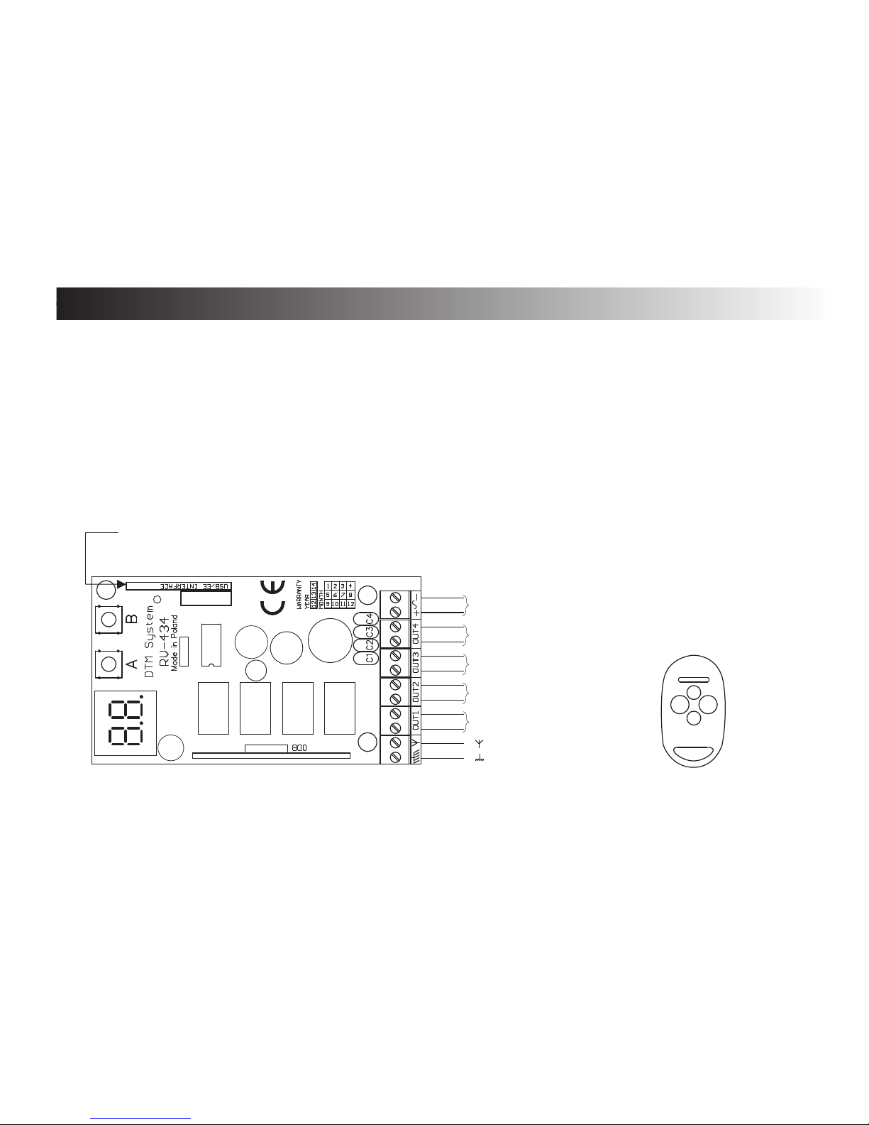
B. Mounting
1. Device description and installation
Rival 434 receiver consists of a main board and a splash-protected plastic enclosure with on outdoor aerial. The
main board (fig. 1) has got terminal blocks for connecting the power supply or peripheral equipment.
The case has got a terminal for the external aerial and it is equipped with a fix-holder.
It is possible to mount the receiver’s main board directly in the case of the controlled device (using the additional
mounting set added to the Rival 434). The additional set consists of: sticking stand-offs for mounting the main board
outside the case (3 pcs.); a cable ring connector and plastic distances to make the outdoor aerial, made out of unused
receiver’s case and wire aerial; a wire indoor aerial; Working temperatures of the receiver are -20°C to +50°C at normal
humidity. Red LEDs are showing actual operating state (they glow as long as the corresponding channel is on).
Supply voltages: 12V - 24V AC/DC (switching converter is built in) or by USB port.
Fig. 1 Rival 434 installing diagram
3
1
2
3
4
Fig 2. NEO 4remote control with buttons
numeration.
Antenna
( )
( )
power supply
12V do 24V DC/ AC
C4 (NO)
USB conector for
PC or cloning
module B700
C1 (NO)
C2 (NO)
C3 (NO)
Page 7
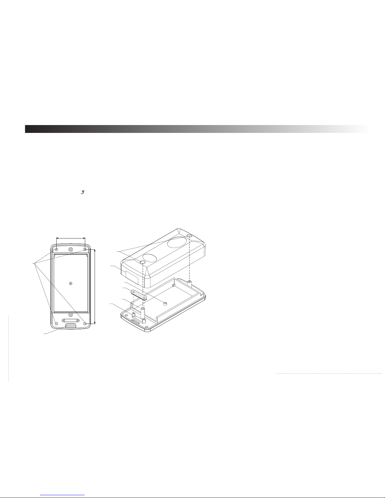
2. Receiver’s installation:
- Open Rival 434 enclosure (take off top part - fig.3). Access to receiver power supply terminal, channel terminals 1,2,3,4 and antenna terminal
is direct.
- Mount bottom part of enclosure, use mounting openings (fig.3 element 2). Enclosure mounting should enable wires connection from the
bottom. Depends on instalation (surface or inside) right weakenings of enclosure should be taken out (fig.3 element 1 or 7), wires should be
connected through resulting openings.
- Connect control wires and power supply
- Mount wires through clip to hold them (fig.3 elements 3 and 5) to secure from rip
- Turn on power supply and program receiver according to needs, see operating manual next chapter
- Connect antenna to " " signed terminal. If antenna's range is not enough use outdoor aerial right for 433MHz (not included in set). In case
outdoor aerial mounting use right wire (ex. RG58) according to aerial producer instructions.
- Mount the top case-side back.
4
Fig. 3 Rival 434 enclosure look
3
4
5
1
2
6
7
8
39 mm
102 mm
Legend:
1. weakening for wires in bottom part of enclosure (inside
instalation),
2. weakenings for receiver mounting,
3. clip to hold wire,
4. chamber for electric plate,
5. wire clip clousure,
6. distance sleeve for plate mounting
uk³adu elektronicznego (screw 2,2 x 6,5),
7. weakening for wires in top part of enclosure (surface
instalation),
8. case closing openings,
Page 8

5
3. Electrical connection
Electrical supply ( + - or ~ )
The receiver can be supplied with voltages from 12V to 24 AC/DC (120mA max). It is possible to use the
internal voltage from the gate controller. Otherwise, some external power supply is needed, for example
ZAS ZSP-4ZEW. It is possible to supply the receiver only by USB port.
Receiver’s outputs (OUT1...OUT4)
Receiver’s outputs 1...4 has three terminals: NO (normally open) Maximum ratings for these contacts are
1A/24V (AC).
USB connector / EEPROM interface
The pin connector on the main board may be used to:
- connect PC (USB interface and cable needed),
- clone (copy) EEPROM memory (EEPROM interface B700 needed).
Antenna connector
Receiver has antenna conncector, signed “ ", where 175mm wire-antenna should be connected. If necessary
connect outside antenna through right wire to “ “ - signal and “ “ screen.
Hints for making the optimal radio range:
- the neighbourhood of the energetic devices and metal elements will short the range;
- radio interference from other sources will short the range;
- avoid wet and concrete walls for mounting the receiver;
- remember to remove old used batteries from the remotes;
- mount the receiver as high as possible;
- use the good quality coaxial cable for making the outdoor aerial (e.g. RG 58)
Page 9
6
Electronics
Module
10 11
2
7
Power supply 24 VAC
Step by step control
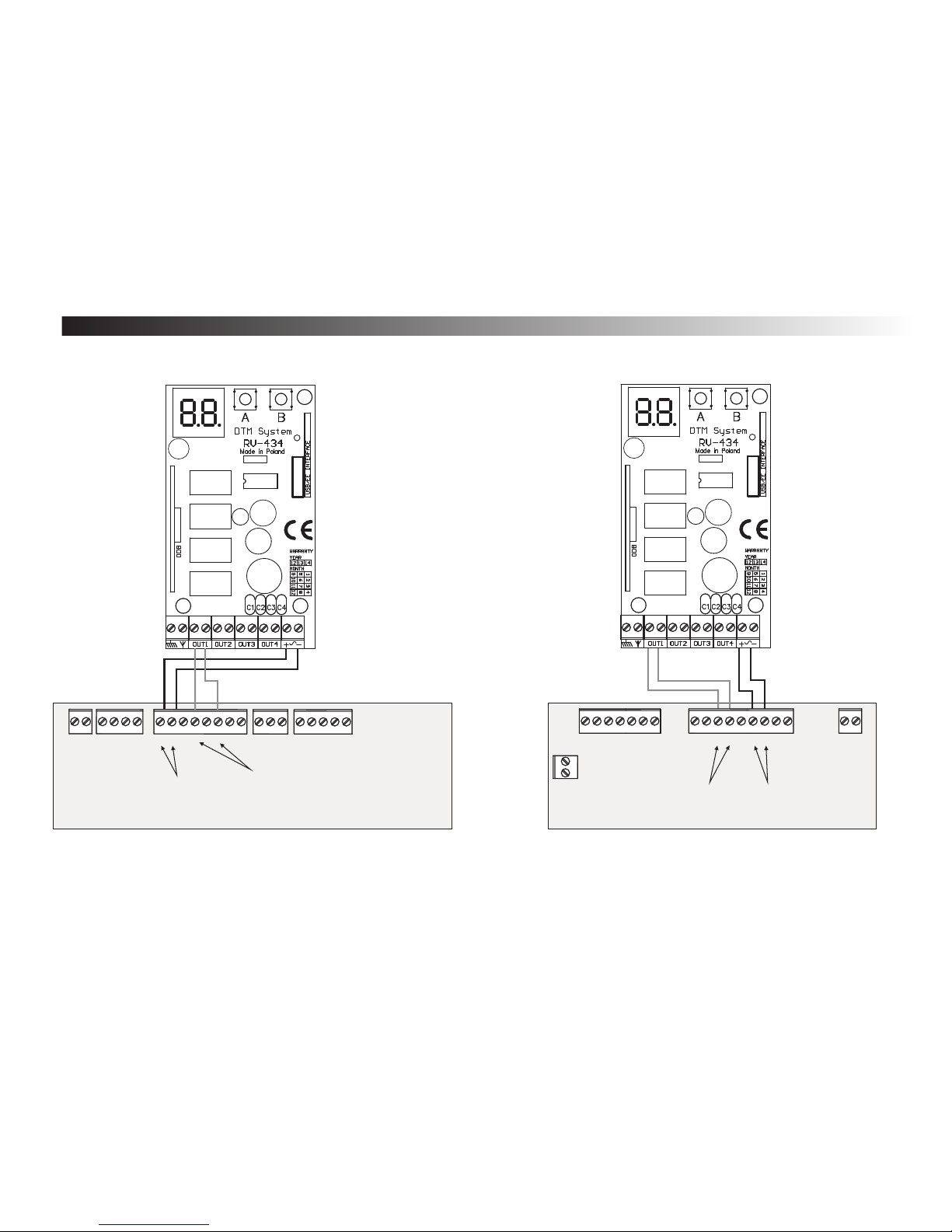
4. Examples of ZSP Rival 434 use:
CAME ZBX7
gate controller
Rival 434 module
Scheme 1. Example of CAME ZBX7 gate controller and Rival 434
connection
Electronics
module
11 10
2
7
Power supply 24 VACStep by
step control
CAME Zf1 gate
controller
Rival 434 module
Scheme 2. Example of CAME ZF1 gate controller and Rival 434
connection
Other terminals
Other terminals
Page 10
7
Electronics
module
+
-
Power supply 24 VDC
Step by step control
20 21 5
Other terminals
Rival 4 34 module
1
Electonics
module
Power supply 24 VAC
Joint terminal
Other terminals
NICE gate
controller
Rival 434 module
Step by step
control
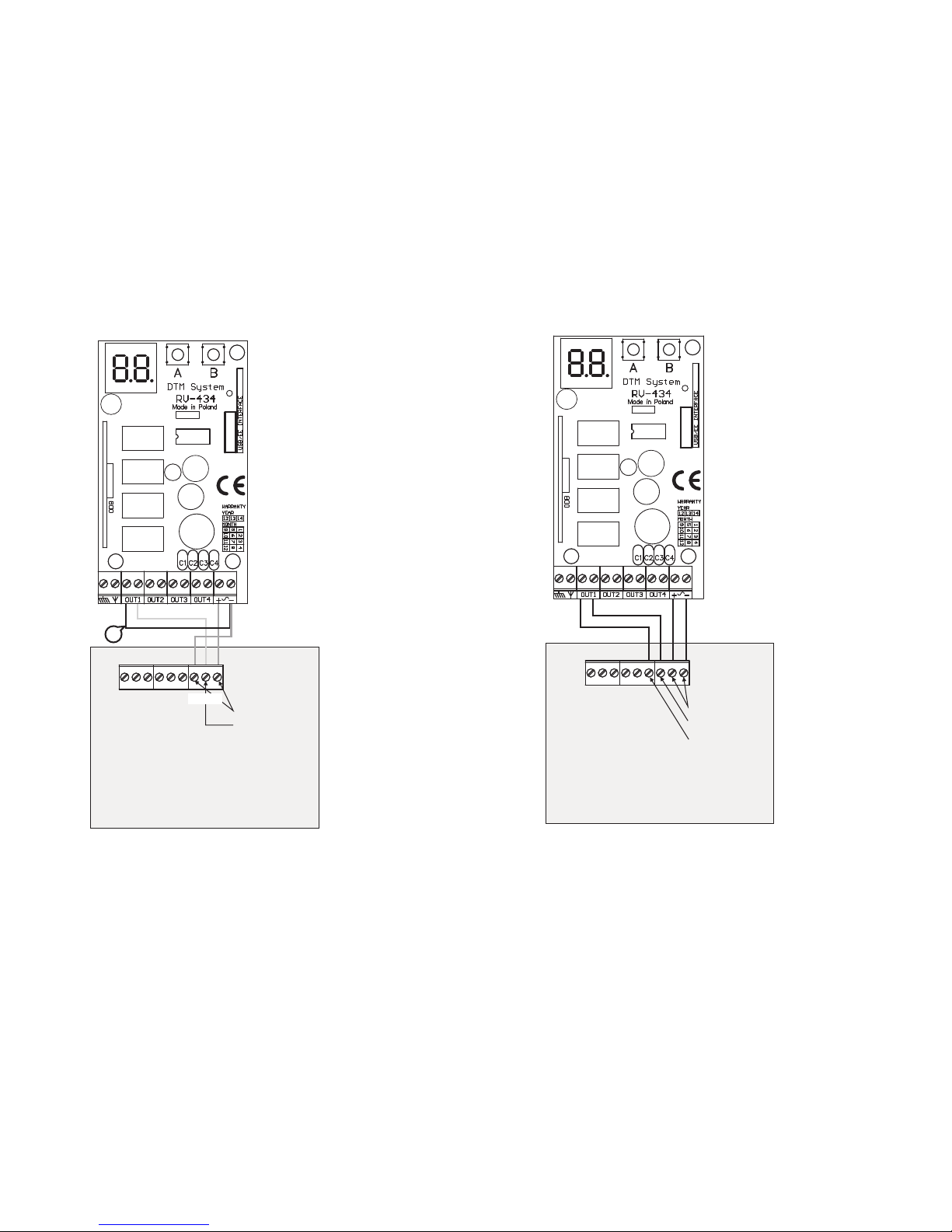
Scheme 4. Example of NICE gate controller and Rival
434 connection
Scheme 3. Example of HORMANN 2 gate controller and Rival 434
connection
Control take place by
connecting ground
petencial (-) through wire
(1) to Rival 434 channel.
Hormann gate
controller
(Supramatic E
buttons
description)
Page 11
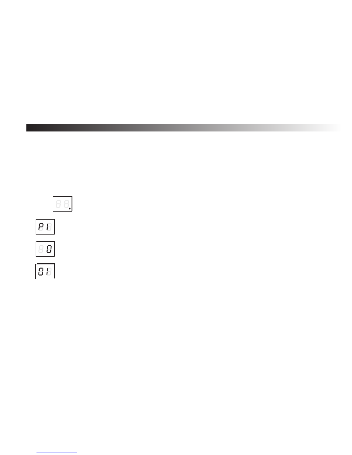
C. Operation mode
Description:
After turning on the power supply, the receiver goes automatically into the OPERATION MODE - it is
signalized by glowing of the LED dot on the right side of the display. In this mode, remote controls the receiver’s
outputs. After pressing the programmed remote’s button, the proper output will be turned on according the
preferences made by the user - the LEDs corresponding to the channels show actual outputs state.
Indications of the display:
In the stand-by mode only the dot on the right side of the display glows.
After pressing any button of the programmed remote, the display will show: the number
of remote’s button and the number of the remote in the receiver’s memory.
All this information will be shown in three phases as on the example in the left: P1 - means that
channel number one was activated, the next numbers (0) and (01 ) show the number of the
remote in receiver’s memory - 001.
Remarks !
After turning on the power supply, the receiver goes automatically into the OPERATION MODE.
4
If the receiver is connected to USB interface, the display will show U sign (see page 28).
4
8
Page 12
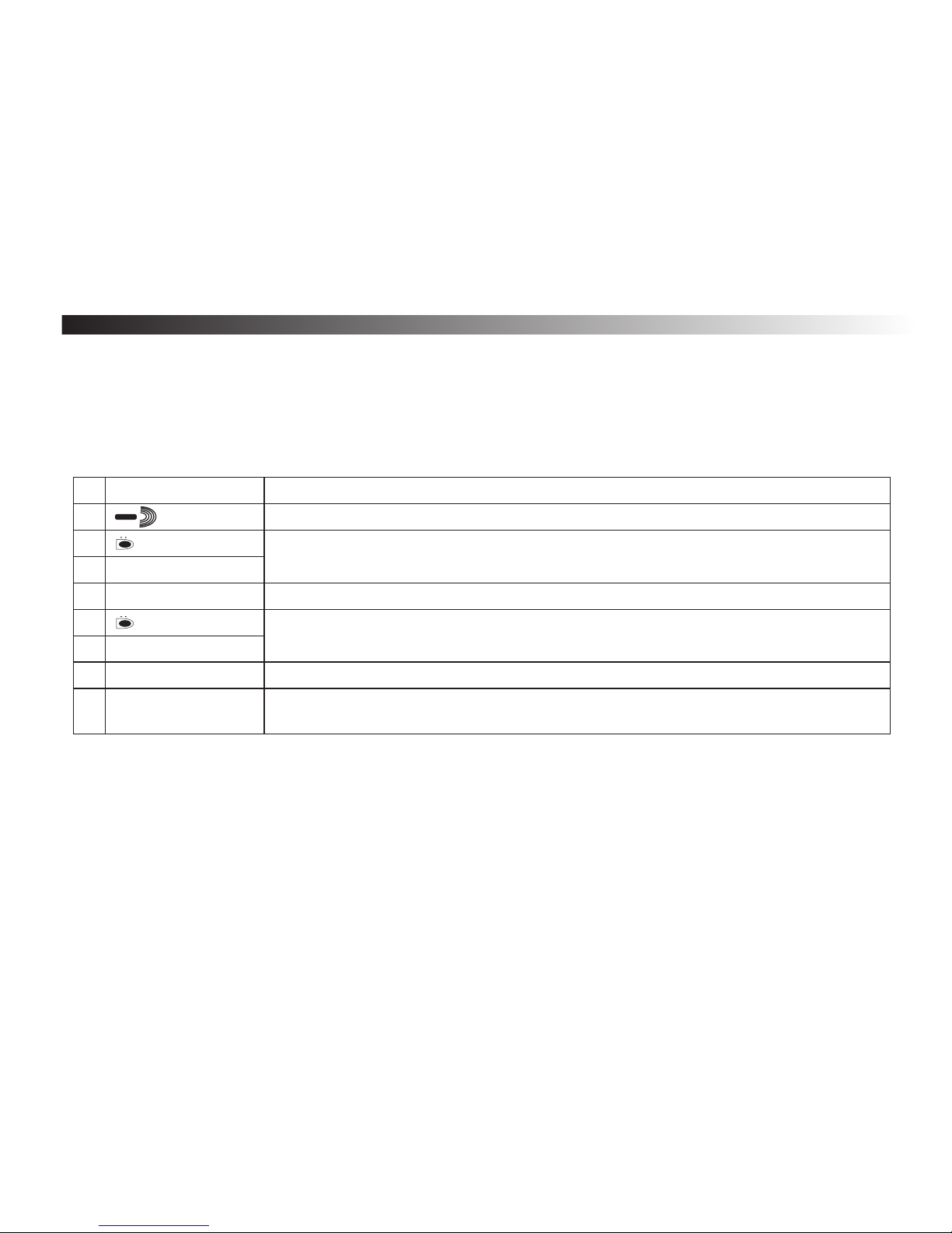
D. Simple registering of the remote without using the receiver’s buttons
Rival 434 has a feature allowing a user to add a new remote to the receiver’s memory without using the
receiver’s buttons. This feature is useful only if any registered remote is also available.
The bc option from the receiver’s menu (see page 16) can block this feature for the specific remote. It is also
possible to block this feature for all the remotes (see page 23).
Simple registering procedure.
Remarks !
The possibility of registering a new remote without using the receiver’s buttons will reduce the safety of the
4
system. The remotes with bc a turned off option should be protected against any unauthorised persons.
You can not use a button working in momentary mode for this procedure.
4
Tab. 1
9
C
L
6
6
6
Remarks
You have to be as close as possible to the radio receiver (but no closer than 1m). The receiver must be in the OPERATION
MODE.
Press and hold for 15 seconds button 2 of the remote that is already in the receiver’s memory. The simple registering
blockade for this remote must be turned.
The pause between operations number 3 and 5 must be less than 3 sec.
Press button 2 of a new remote for at least 15 seconds.
The new remote has been registered in the receiver’s memory. The preferences for this remote have been copied from
preferences of the remote used for registering (from operation no 2).
It was not possible to register a new remote. Possible reasons: - too big radio interferences. - The battery of one of the
remotes was too low for such a long transmission.
Operations
Radio range
Button of the already
registered remote
>15 s
<3s
Button of a new remote
>15 s
The remote has been added
Adding has failed
1
2
8
Pos.
4
6
3
5
7
Page 13
10
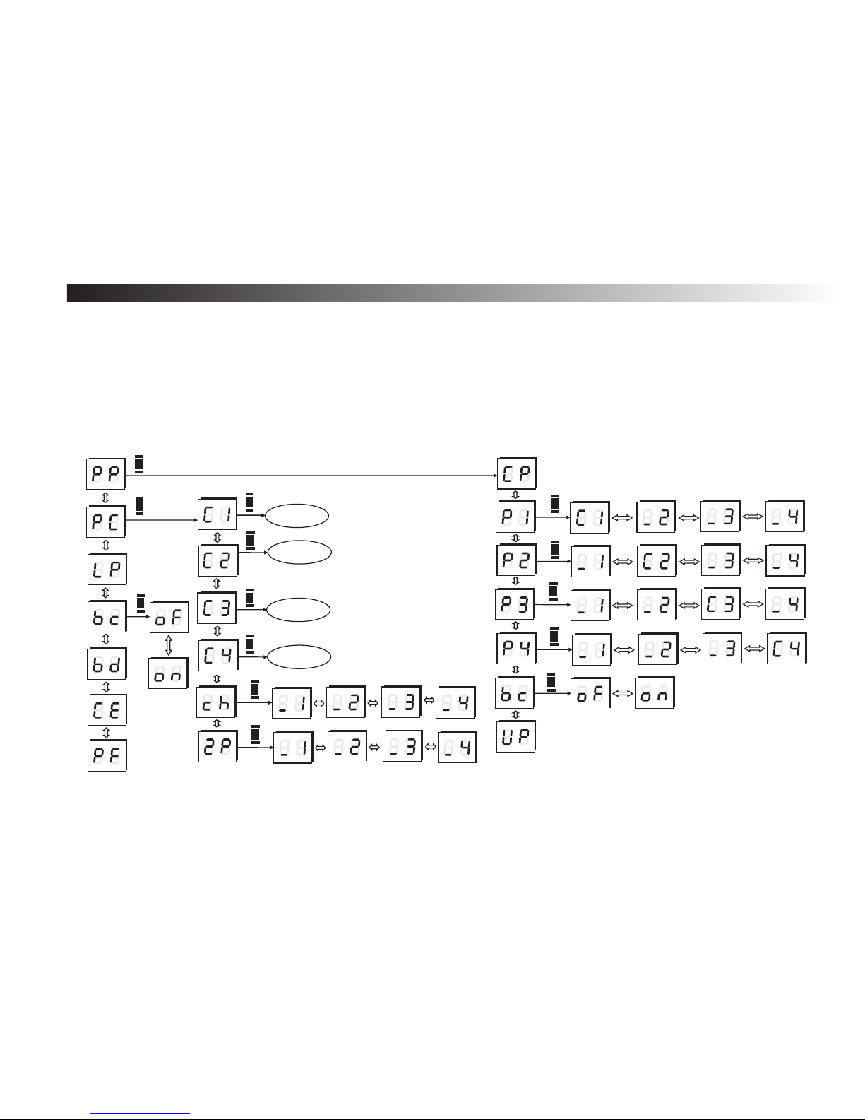
E. Receiver's programming - introduction
All the programming can be done with the LED display, the receiver’s buttons A and B, and four buttons
of any DTM433MHz remote.
The remote’s buttons has attributed directions keys that move through the program menu.
Use up/down keys of the 4 button remote to move vertically in the menu and left/right to move horizontally.
The receiver’s button A is used for confirmation, the button B is used for cancelling and going up in the menu
structure.
The receiver’s program menu has a tree structure that consists of major and minor options. For further
information, look in to the next chapters.
Fig. 5 The structure of the receiver program menu.
Time edition
Time edition
Time editon
Time edition
A
A
A
A
A
A
A
A
A
A
A
A
A
Remote declaration
A
A
Page 14
11
1. Main menu
The receiver’s configuration can be adjusted to a user’s needs. The
program’s options allows registering remotes to the receiver, defining one or
many receiver outputs to the remotes buttons, removing any remote from the
receiver’s memory, the configuration of receiver's outputs.
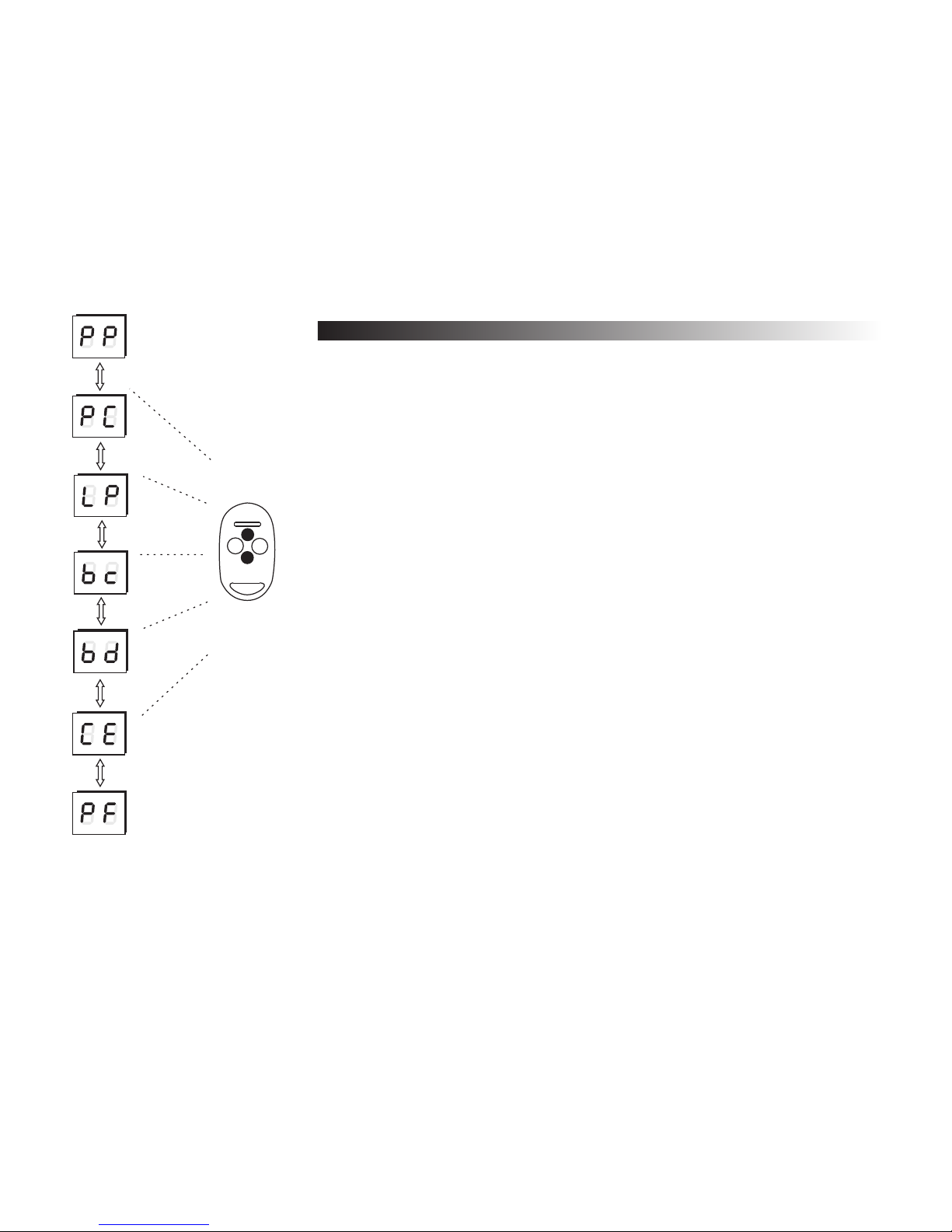
To enter the PROGRAMMING MODE press A. The options can be chosen by
pressing up/down buttons of any 4 button NEO remote.
The main menu options:
PP- remotes programming (registering, deleting, copying, bc option) -
see page 12
PC- channels configuration (mono- / bi-stable mode, momentary mode,
double push button, turn on time) - see page 19
LP- number of remotes registered in the memory - see page 22
bc- simple registering blockade for all remotes - see page 23
bd- setting PIN number - see page 24
CE- memory cloning - see page 26
PF- default settings - see page 27
REMARKS: The remote which is used for the first time after entering
PROGRAMMING MODE (after first A button pressing) will be used for the
programming session - it will be called 4-button remote.
Fig. 6 Main menu options - available after declaring the remote which will be
used during programming session.
REMOTE
1
2
3
4
Page 15
12
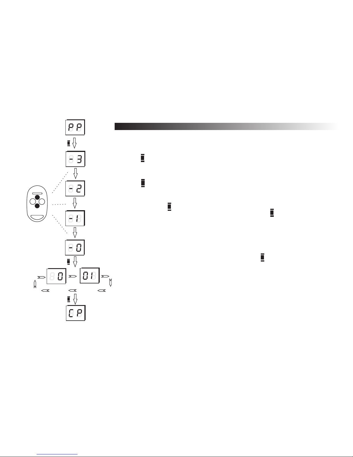
1.1 Registering a new remote
The PP option is the first in the main menu.
A
A
A
Remote being
registered.
Remarks !
B
It is suggested to write down all the information about the newly registered
4
remotes in the identification card from the remotes package and to the remotes
table (see page 28).
Tthe additional EEPROM module can be used B700 for archiving - see page 26.
4
Programming sequence for registering a new remote:
a) press button while PP option on the display.
b) press the button of the remote that is to be registered, 3 times until you get -0 on
the display,
c) press button to confirm registering,
d) the position number in the memory of the new remote will be shown on the
display. At first, hundreds of the number, then tens and ones (001 in the
example), press button to confirm,
e) new remote has been registered in the memory. Press button twice exit the
menu or once to go back to PP option to register another remote.
A
B
AA
AA
1
2
3
4
Fig. 7 New remote registering procedure.
It is possible to go back in the menu by pressing the button.
4
Page 16
13
1.2 Editing of the existing remote
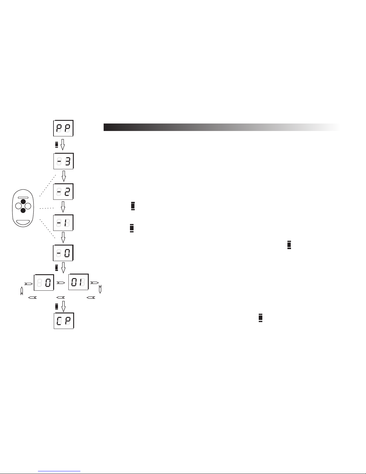
In the PP option it is also possible to edit the preferences of already
registered remote (changing remote’s buttons to receiver’s outputs, removing the
remote, copying preferences from remote number 001, etc).
First the remote to be edited must be declared.
Declaring the remote to be edited:
A
A
A
a) press button while PP option on the display (change options by pressing
up/down buttons on the remote button)
b) press 3 times button of the remote to be edited, (until you get -0 on the display),
c) press button in the receiver,
d) the number of the declared remote will be shown on the display (the hundreds
column first, then tens and ones columns of the number). Press button to
confirm.
e) the remote is now declared and editing options are available (CP, P1...P4, bc,
UP).
A
Edited
remote
Remarks !
B
You can go back (cancel) in the menu by pressing the button any time.
4
A
A
1
2
3
4
Fig. 8 Declaring the remote to be edited
Page 17
14
1.2.1 Copying the remote’s preferences from remote no 001
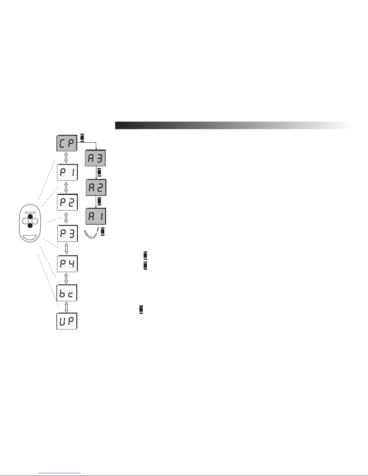
After declaring the remote to be edited, all edit options are available. Use
up-down buttons in the remote to change the sub options:
CP - copying remote’s preferences,
P1...P4 - declaring receivers outputs to different remote buttons - see page 15,
bc - simple registering blockade (individually for every remote - see page 16,
UP - deleting the remote (page 17).
Copying the preferences from the first 001 remote:
a) press button while the display shows CP.
b) press button 3 times while A3 option on the display.
The edited remote has the preferences copied from the first one.
Copying settings from the first remote (number 001) makes editing much
easier and faster. It is useful when more remotes have the same settings which
are different from the default ones.
Remarks !
The first remote (no 001) should have the preferences required mostly.
4
The button allows to go up (cancel) in the menu any time.
4
It is possible to use this feature without the physical presence of the remote
4
(see page 18).
A
A
A
A
Fig. 9 Copying remote’s preferences procedure
B
Back to
option CP
A
REMOTE
1
2
3
4
A
Page 18
15
Remarks !
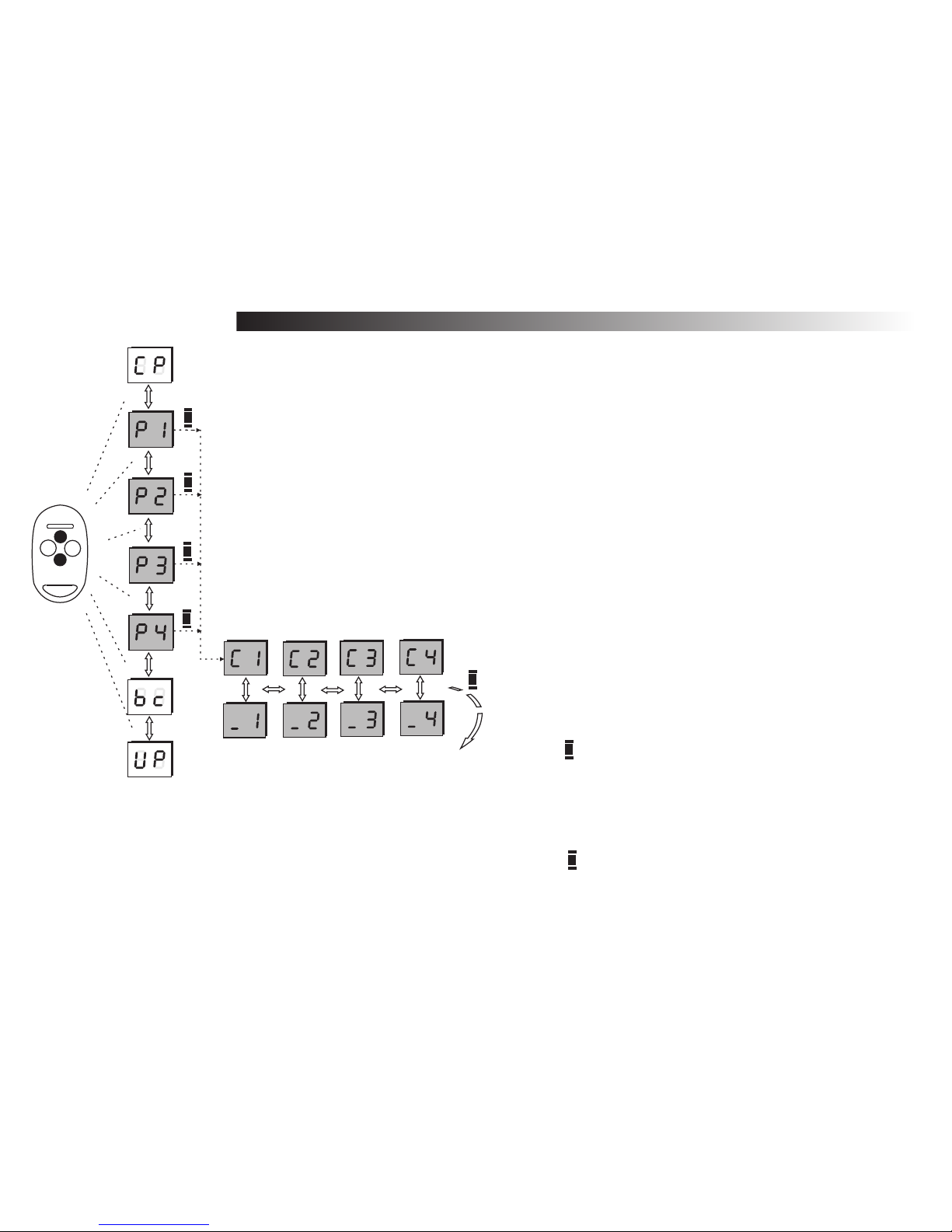
1.2.2 Defining channels to the remote’s buttons
After declaring the remote to be edited, all edit sub options are available. Use up/down
buttons in the remote to change the sub options:
CP - copying the remote’s preferences - see page 14,
P1...P4 - define channels to the remote’s buttons ,
bc - simple registering blockade (individually for every remote) - see page16,
UP - deleting the remote - see page 17.
New registered remote gets the default preferences:
Button 1 - channel 1,
Button 2 - channel 2,
Button 3 - channel 3,
Button 4 - channel 4.
This option allows to change these settings. It is possible to attach few buttons to the same
remote button, etc.
Changing the definition for the channels to the remote
buttons:
a) choose the proper option P1...P4 for the button which is
to be edited,
b) press button to go to the chosen option,
c) using left/right buttons choose the channel to be
attached / deleted.
d) press to set up the sign _ (to delete) or C (to define the
channel to the edit button) press up-down buttons.
e) press button to confirm.
A
A
It is possible to change the button’s
4
configuration without the physical
presence of the remote.(page 18).
Fig.10 Define
channels to the
remote’s buttons
A
A
A
A
A
Back to option
P1...P4
1
2
3
4
REMOTE
Page 19
16
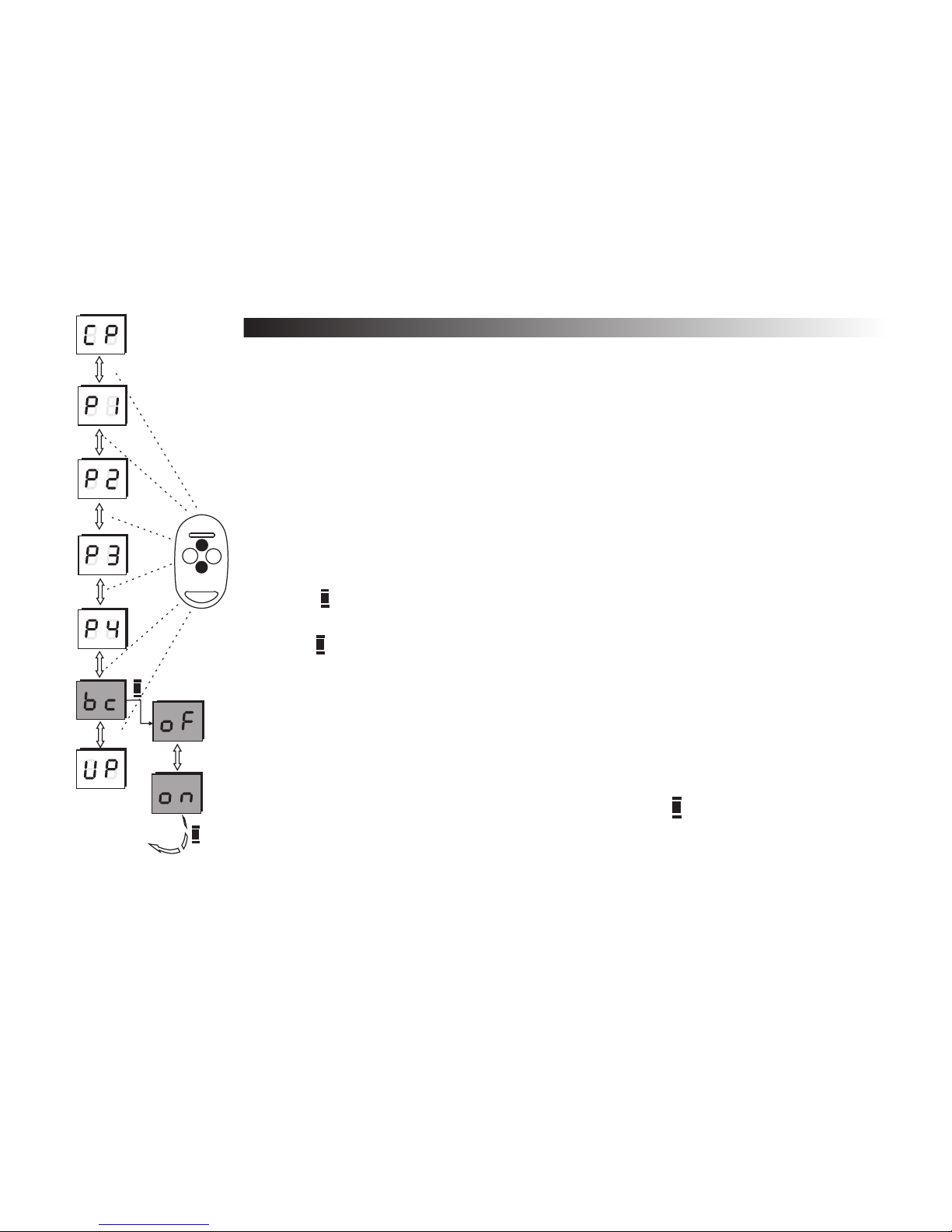
1.2.3 Simple registering blockade
After declaring the remote to be edited, all edit sub options are available.
Use up/down buttons in the remote to change the sub options:
CP - copying the remote’s preferences - see page 14,
P1...P4 - define channels to the remote’s buttons - see page 15,
bc - simple registering blockade (individually for every remote)
UP - deleting the remote - see page page 17.
The option “simple registering blockade” was introduced to give a better safety to
the system - see page 9.
To activate / deactivate of the individual new remote register blockade:
a) press button while the display shows bc,
b) you may active (on) or deactivate (of) the blockade by pressing up-down buttons,
c) press button to confirm your choose.
Remarks !
This blockade function is individual for a particular remote. To change the blockade for
4
all remotes see page 23,
It is always possible to go back in the menu by pressing button,
4
It is possible to use this function without the physical presence of the remote (page
4
Fig.11 Blocking simple registering
A
A
B
1
2
3
4
A
A
Back to
option bc
REMOTE
Page 20
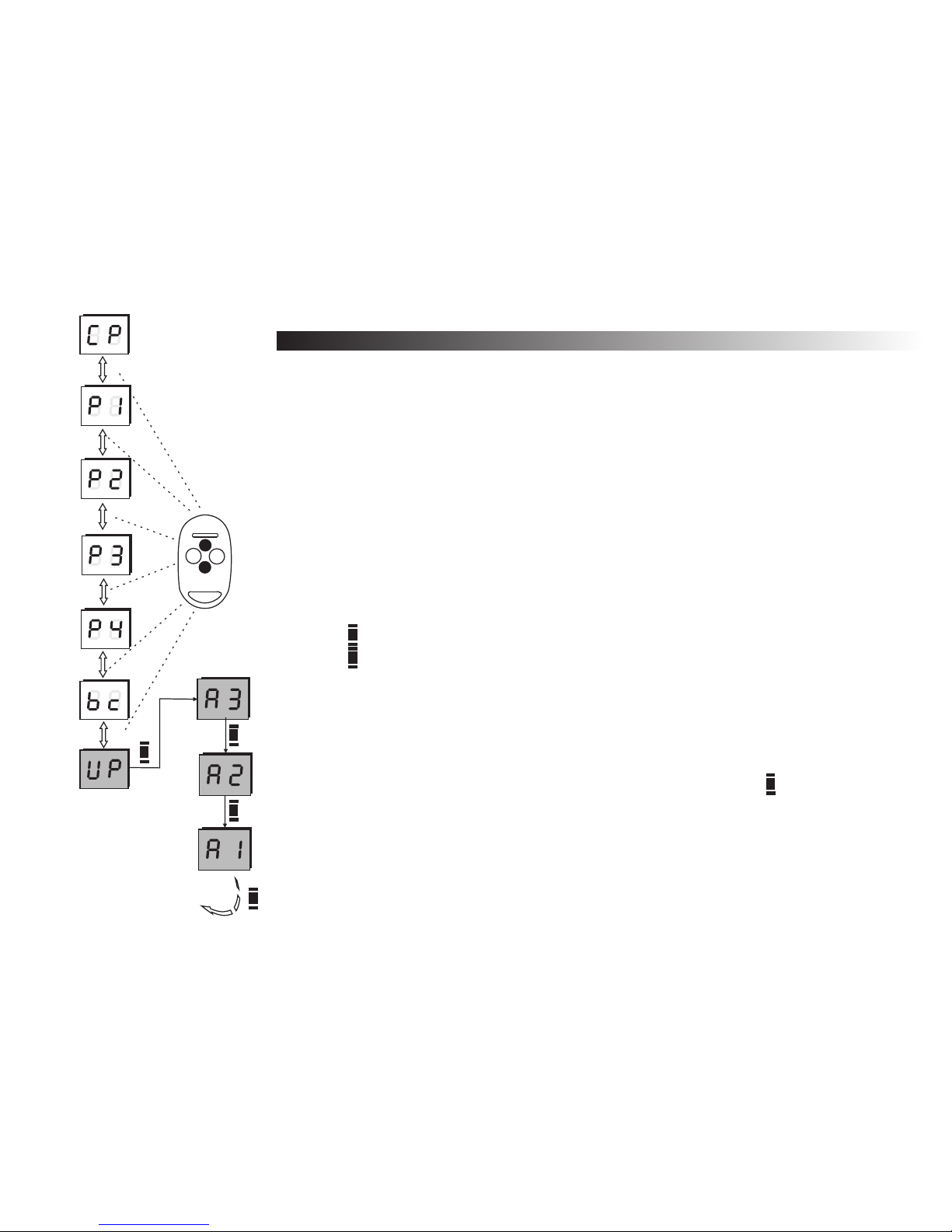
1.2.4 Deleting the remote
After declaring the remote to be edited, all edit sub options are available. Use
up/down buttons in the remote to change the sub options:
CP - copying the remote’s preferences - see page 14,
P1...P4 - define channels to the remote’s buttons - see page 16,
bc - simple registering blockade (individually for every remote) - see page 16,
UP - deleting the remote
This option is used to delete one of the existing remotes. All the other numbers of
the existing remotes will be kept. When another remote will be added to the system - the
number it gets, will be the first available.
To delete a remote:
a) press button while the displays shows UP,
b) press button while displays shows A3 three times.
1
2
3
4
REMOTE
A
A
A
A
Back to
option PP
Remarks !
To keep the position number of a temporarily unavailable remote in the receiver’s
4
memory you must disconnect all channels from the buttons (options P1...P4),
4It is possible to go back (cancel) in the menu by pressing button ,
It is possible to delete a remote without the physical presence of the remote - see
4
page 18.
A
A
17
Fig.12 Deleting the
remote
B
Page 21

18
1.3 How to edit the remote's settings without physical presence
The system allows to take advantage of functions such as copying the remote’s settings, changing the
button’s configuration, simple registering blockade, and deleting the remote without its physical presence - the only
thing needed is the remote's number. All the remotes data should be stored in the table - see page 32 or in the PC
file - see page 28. This possibility is very useful in the case of theft, for example or when a particular channel
number is to be changed and the configuration of the rest of the remotes must be updated.
The one difference between using the remote without and with physical presence is declaring it for the edition. All
the actions mentioned here are similar to the ones from 1.2.1 to 1.2.4 points.
To declare a remote for editing without physical presence:
a) press to go into programming mode,
b) press button while displays shows PP,
c) press button once more while the displays shows -3. The first serial number (of hundreds) will be shown on
the display. Use up-down buttons in the remote to set-up the proper value and left-right buttons to move
between the edited numbers of hundreds columns, tens, and ones columns. The hundreds reading as one
number, the tens parts, and ones of the number are shown side by side. (Two numerals: adequately shown
from left the tens and ones of the number),
d) press button to confirm. The display shows the setted serial number,
e) press button once more to confirm. You will get the access to the options for editing the remote.
Remember, the edited remote will be the one which serial number was manually setted-up in point c.
Follow points 1.2.1 to 1.2.4
A
A
A
A
A
Page 22
Display
1 2 3
0 0 0 0 , 5 [sec]
1.4 Channel time settings
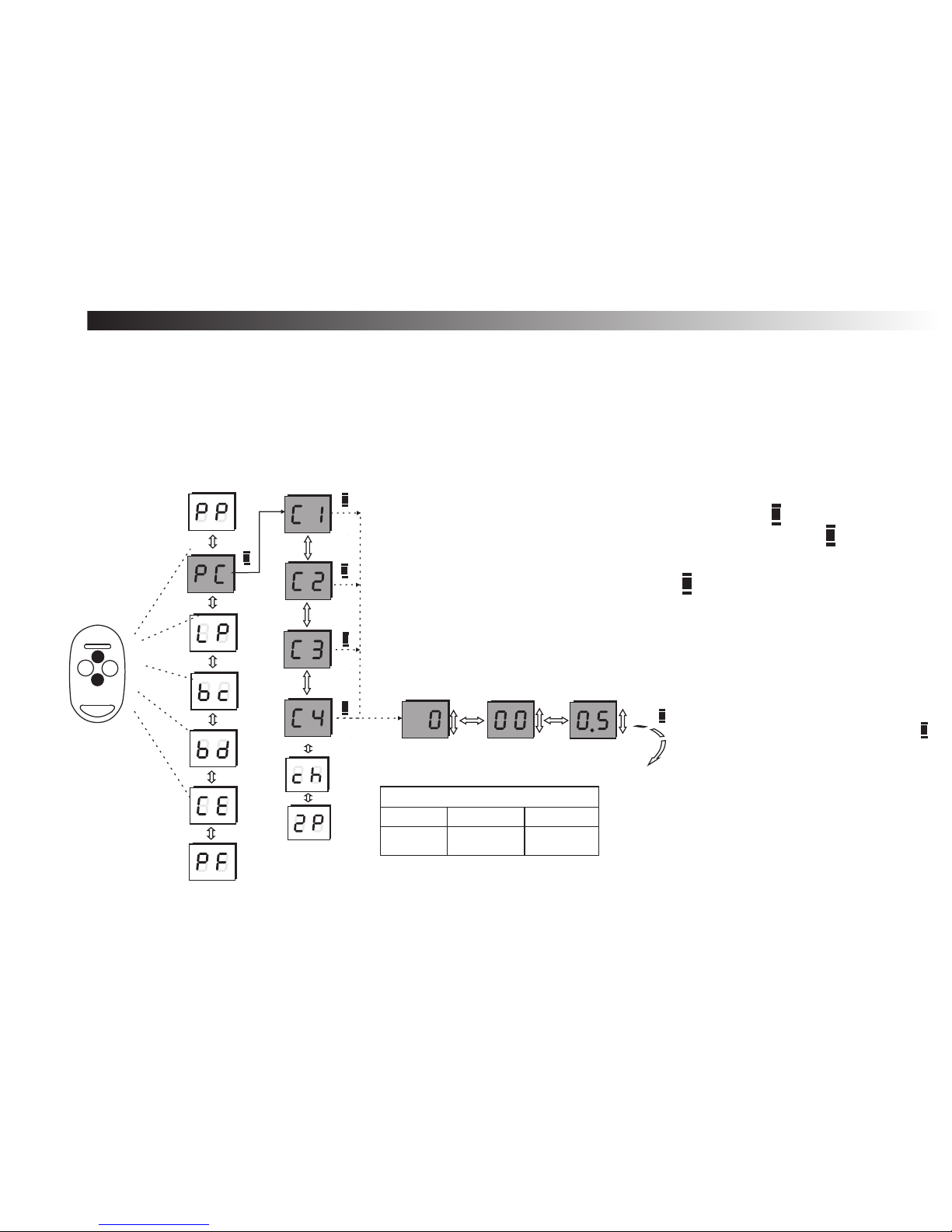
The second menu’s option is PC which allows changing modes and the channel’s turn on times.
The possible turn on time is between 0,1 sec and 6553,5 sec (about 110 min.) . Turn on time resolution is 0,1
sec. Setting 0 sec. turns the channel into the bistable mode. The default settings for each channel are: 0 00 05 - which
means 0,5 sec.
Change the actual edited number by pressing left-right buttons. To edit the pulsating number press up-down buttons.
A
A
A
A
A
Thousands sec.
Hundreds and
tens sec.
Ones and tens of sec.
+-+
-
+-+
-
-+-
Back to option
C1...C4
A
To program the receiver’s channels:
a) use up/down buttons to choose option PC and press button,
b) use up/down buttons to choose a channel C1...C4 and press button,
c) to edit the pulsating number press up/down buttons and to change the
edited number, press left/right buttons,
d) to confirm the turn-on time, press button ,
Remarks !
To turn on the bistable mode, set
4
the time to 0 sec..
It is possible to go back (cancel)
4
in the menu by pressing button
If the channel is set to work in
4
momentary mode - )see page
20) - the display will show --.
Setting any time will turn this
mode off.
A
A
A
B
1
2
3
4
REMOTE
Fig.13 Receiver
19
Page 23
A
A
REMOTE
A
20
Back to option
c h
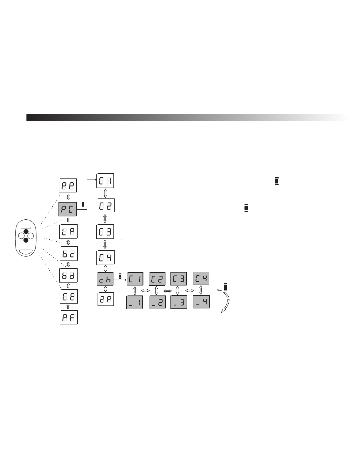
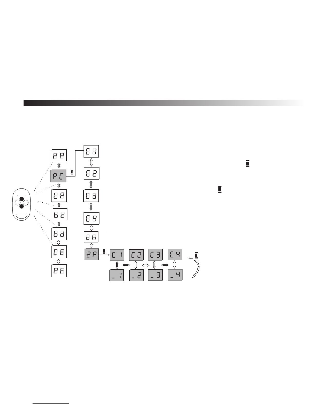
1.5 Momentary mode
This option sets the channel into momentary mode when the output relay is turned on as long as the remote's
button is depressed (after button release the relay goes off).
The maximum turn on time is 25 sec. After that time the remote turns off to save the battery and it may be pressed again
for another 25 sec.
Fig. 14 Setting momentary mode procedure
To set momentary mode on any of the channels:
a) use up/down buttons to choose option ch and press button,
b) the display will show the channel number, use up/down buttons to choose
between C symbol (momentary mode) or _ symbol (normal time settings),
c) to change the edited channel, press left/right buttons,
d) to confirm the turn-on time, press button ,
A
A
1
2
3
4
Page 24
A
A
A
21
Back to option
c h
1.6 Double-click mode
After setting this option, the remote's button have to be double-pressed (double-clicked) to activate the
receiver's output. The second click have to be within 3 seconds from the first one. It is not possible to set this function
when the channel is in momentary mode. If the channel is set to work in the bistable mode, the remote's button has to be
pressed twice for activating the channel and only one for deactivating it.
This feature reduces the possibilities of activating the channel by mistake.
Fig. 15 Setting double-click mode procedure
To set double-click mode:
a) use up/down buttons to choose option 2P and press button,
b) the display will show the channel number, use up/down buttons to choose
between C symbol (double-click mode) or _ symbol (normal),
c) to change the edited channel, press left/right buttons,
d) to confirm the turn-on time, press button ,
A
A
1
2
3
4
REMOTE
Page 25
22
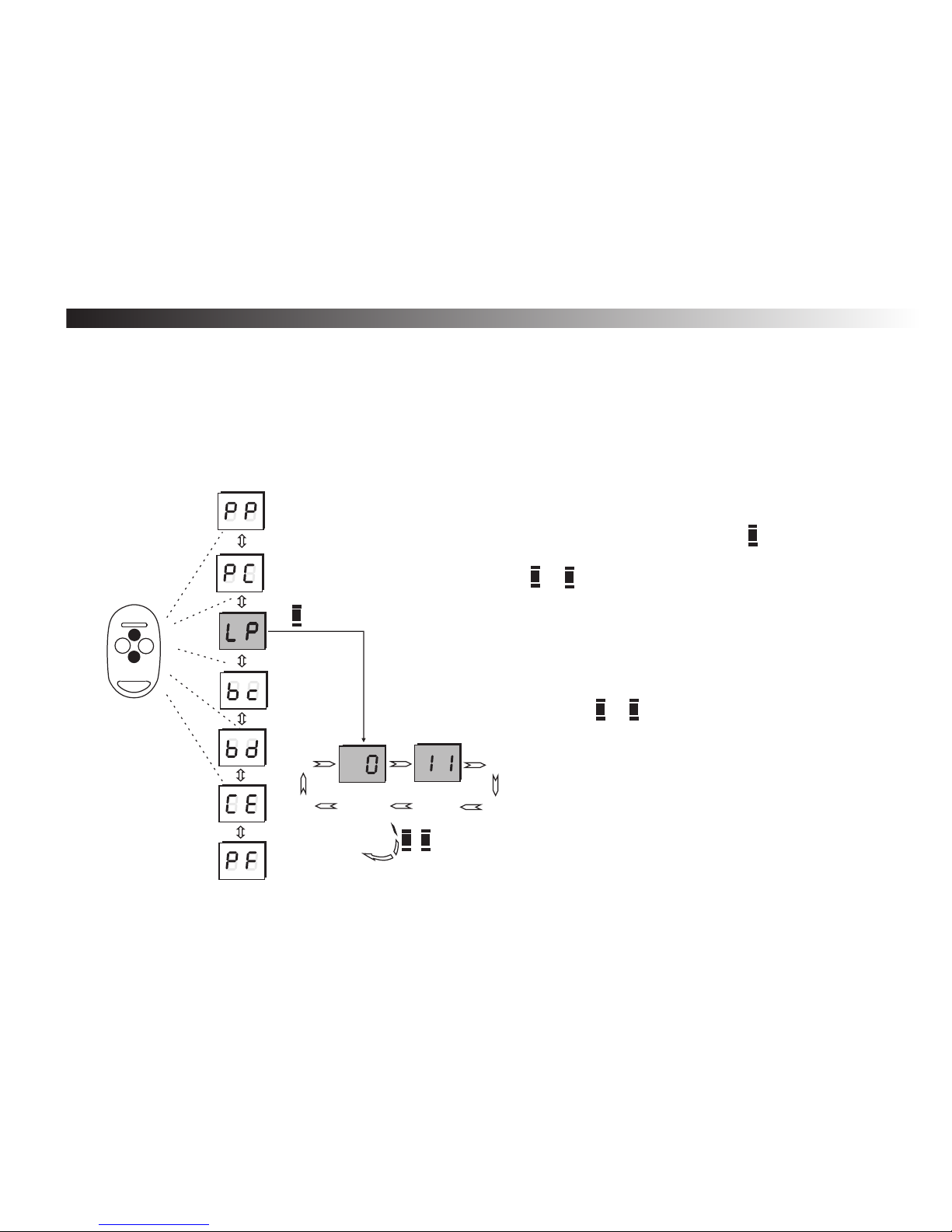
The third main menu’s option is LP which shows the actual number of registered remotes. After choosing the
LP option, the display will show the number divided in two parts: hundreds, tens and, ones columns e.g. If the first part
is 0 and the second one is 11 it means 011.
The maximal possible number of remotes registered in the Rival 434 memory is 700.
To check the actual number of registered remotes:
a) use up-down buttons to choose option LP and press button,
b) the display will show the actual number of registered remotes. Return to the
menu by pressing button or .
Remarks!
4
Press or button to cancel.
1.7 Number of registered remotes
A
A
B
Fig. 16 Checking the
number of registered
remotes procedure.
A
B
1
2
3
4
A
A
B
Back to
option LP
REMOTE
Page 26
23
1
2
3
4
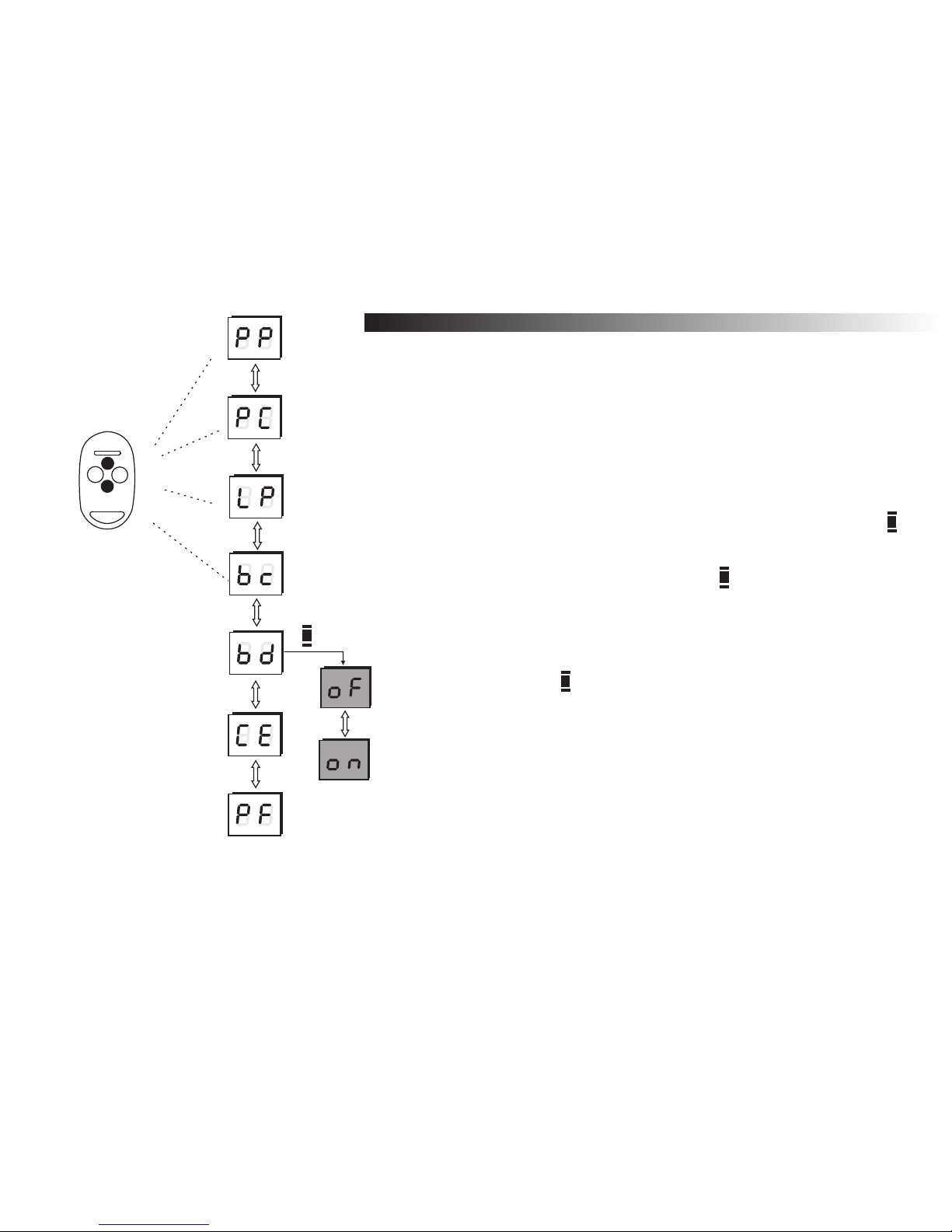
The bc option from the main menu blocks simple registering feature for
all (global) already registered remotes.
This blockade can be activated (on) or deactivated (of - which is default setting).
To set the blockade of simple registering for all already
registered remotes:
a) use up/down buttons to choose option bc and press
button,
b) use left/right buttons to activate (on) or deactivate (of)
this function and confirm with button.
Remarks!
4
After setting, this blockade will also be active for all
4
remotes that will be registered in the future.
Press button to cancel.
1.8 Simple registering blockade for all remotes
Fig. 17 Setting simple registering
blockade procedure
A
A
A
B
REMOTE
Page 27
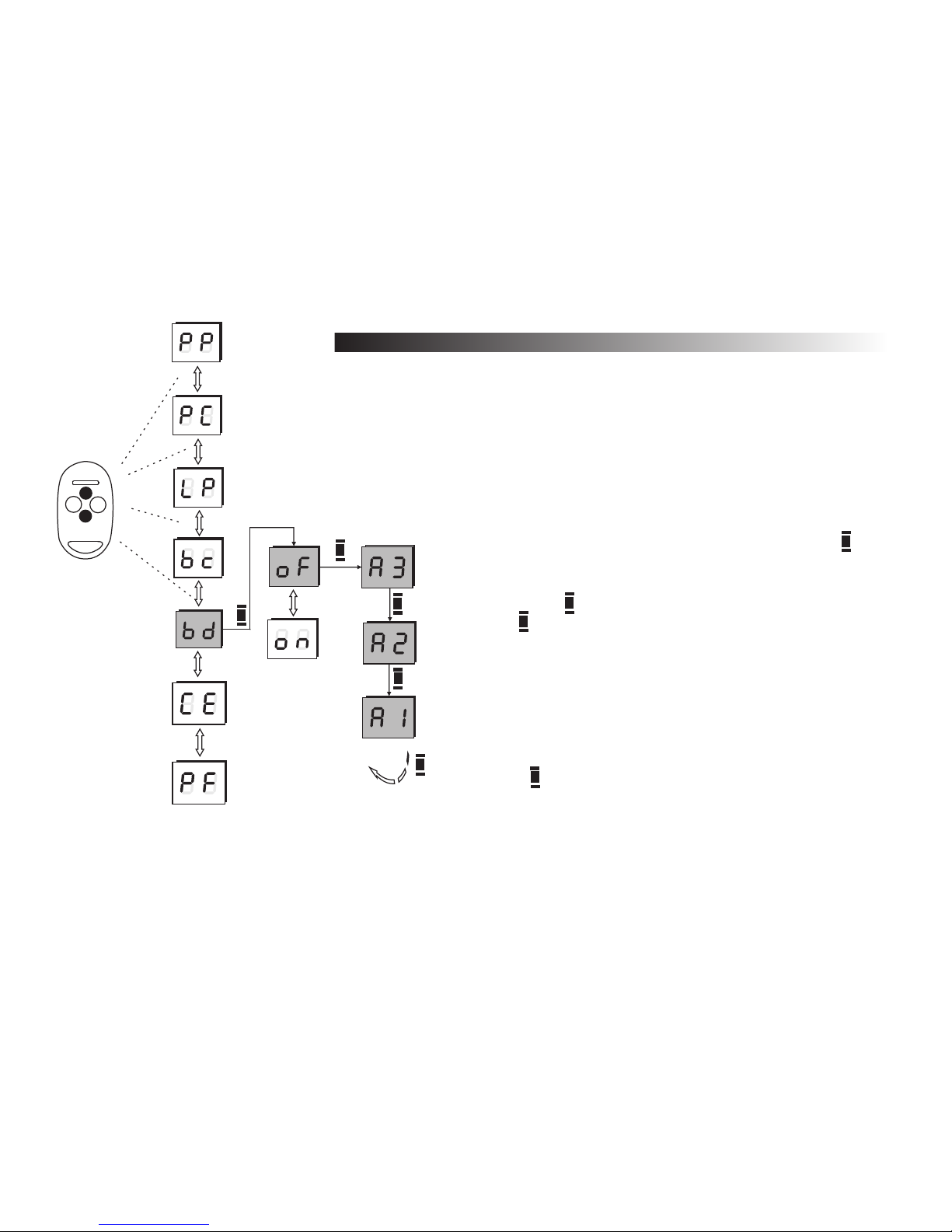
The bd option in the main menu sets PIN number checking at the
entrance to the main menu.
The possible settings are: activated (on), deactivated (of). This option is not
active as default.
To deactivate PIN number checking at the entrance to
the main menu:
a) use up/down buttons to choose option bc and press
button,
b) use up/down buttons to deactivate (of) this function,
confirm with button, when A3 appears on the display,
press receiver button 3 times.
Remarks!
4
Press button to cancel.
24
1.9 Setting restricted access to main menu (PIN code)
Fig. 18 Deactivating PIN
number checking procedure.
A
A
B
A
REMOTE
A
A
A
A
A
Back to
option bd
1
2
3
4
Page 28
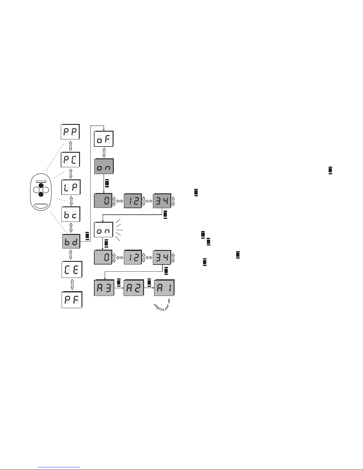
To set activate PIN checking and set new PIN code:
25
Setting restricted access to main menu (PIN code):
Fig. 19 Activating PIN checking and
setting new PIN number procedure
A A
A
Back
to option
bd
A
+-+
-
+-+
-
+
-
a) use up/down buttons to choose option bd and press
button,
b) use up/down buttons to activate (on) this function, confirm
with button,
c) the first digit of the new PIN code will appear on the
display,
d) using up/down buttons choose the right number,
e) press right button to move to next number, follow point d to
set whole value of the PIN number,
f) press button in the receiver, the on sign will appear blinking,
g) press button again to confirm PIN number, set the same
code again,
h) after depressing button, A3 will appear on the display,
press button 3 times.
Remarks!
A
A
A
A
A
A
+-+
-
+-+
-
+
-
A
A
1
2
3
4
REMOTE
4
main menu. In such case only receiver's manufacturer
can unlock it.
Loosing your PIN code will block the ability of entering the
A
Page 29
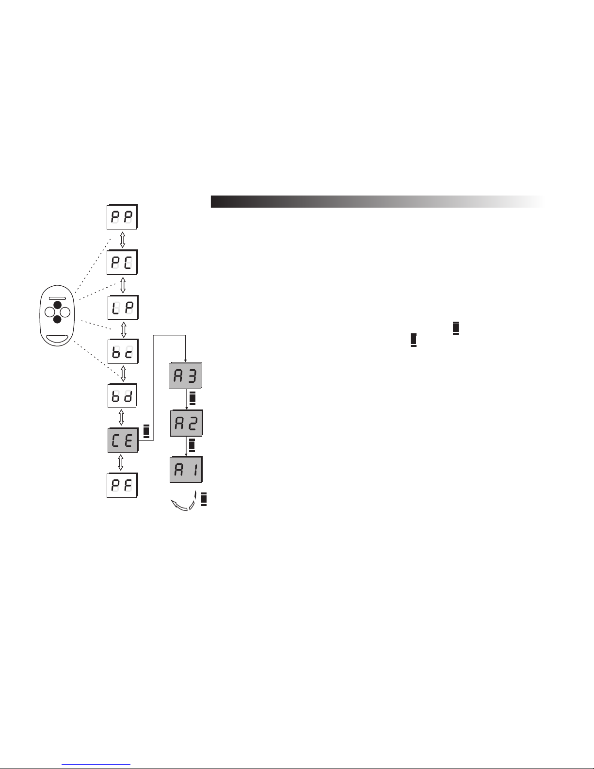
26
1.10 Memory cloning
The CE option allows to copy / clone the receiver’s memory with all the
configuration and all remotes data to another receiver.
This option can only be used with B700 memory cloning module.
To clone the memory:
a) plug in B700 module into pin socket on the main receiver's board,
b) use up/down buttons to choose option CE and press button,
c) A3 symbol will appear on the display, press button 3 times to accept,
d) wait for memory to clone.
During cloning, the display will blink in a characteristic way. After it is
completed the display will show the CE again (main menu).
Remarks !
Place B700 module in the right position. Mind the pins. If it is placed in the
4
wrong way it may lead to receiver or module failure.
If the module is broken or there is no connection between it and the main
4
board, the display will show EE and Er symbols alternatively.
A
A
A
A
Back
to option CE
A
A
Fig. 20 Memory
cloning procedure.
1
2
3
4
REMOTE
Page 30
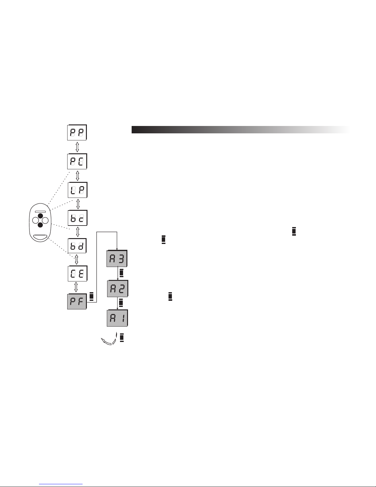
27
1.11 Default settings
The option PF sets back the default settings of the receiver.
The default settings are:
- no remotes registered in the memory,
- all 4 channels working in the monostable mode (0.5 sec turn on time),
- simple registering blockade: off,
- PIN checking: off,
- double-click mode: off.
To reset receiver and set the default settings:
a) use up-down buttons to choose option PF and press button,
b) press button three times while the display shows A3 to confirm the option,
Remarks !
Using of PF causes removal of all registered remotes from
4
the receiver’s memory and sets default settings to all channels.
press button to cancel.
4
option
A
A
B
Fig. 21
Default settings procedure
1
2
3
4
A
A
A
A
Back
to option PF
REMOTE
Page 31

28
The receiver can be connected to a PC computer using a standard USB cable and "Programator USB" PC
software. The receiver is automatically recognised by the PC. The cable and the PC software are available as option.
PC interface is much more user-friendly than the standard receiver's menu and gives some additional features.
Additional options available in PC program:
- additional description added to every remote (e.g. name of the user),
- events register,
- coping memory to file,
- channels control by PC.
To connect the receiver to the PC:
a) plug in the USB interface board with the USB cable according to the manual,
b) the display will show U sign,
c) the receiver will be automatically recognized by the computer,
d) at the first installation the Windows creator will be launched and will guide the used through the
installation process,
e) the set is ready.
Remarks !
PC connectivity is available only with the receiver's software version above 2.0. Receivers with
4
the lower version of code can not be used and have to be upgraded . Contact manufacturer for
details. The actual version of receiver's software can be seen right after powering it (with USB
cable) on the LED display.
While working with USB, the receiver does not have to be powered with external source.
4
All the installation details can be found in the manual added to the USB cable and the interface
4
kit.
Fig. 22 Symbol on the
display during
USB connection
F. Connecting PC (USB port)
Page 32

Receiver MAX
- four separated relay outputs, NO or NC type , working in mono-, bistable or momentary mode, max load for each output 1A/24V AC/DC - the receiver
differentiate up to 700 remotes, each of them addressable
- monitoring, changing and remote deleting possibility, even without remote presence,
- outputs attached to any of the remote's buttons - access control
- simple registering feature,
- EEPROM receiver memory in the socket eases servicing,
- turn on time in monostable mode: from 0,1 sec. to 107 min. (resolution to 0,1 sec.), bistable mode remembers last state before power down,
- information on number of registered remotes,
- memory cloning feature,
- PIN code for better safety,
- PC connectivity (USB port),
- "watch dog" circuit protecting from program flow,
- user interface based on push buttons and LED display,
- terminal for external aerial coaxial cable,
- plastic, splash resistant enclosure,
- supply voltage: 12V to 24V AC or DC, integrated switching stabilizer,
- working temperatures: from -20 C0 to + 55 C0,
- dimensions: enclosure: 80 (plus 40mm holder) x60x30mm, without case: 74x50x18mm,
- working frequency: 433.92 MHz
G. Specifications of DTM System elements
29
NEO and TIP Remote
NEO remote
- modern and ergonomic shape
- four (two) buttons that can control any channel or the group channels,
- signal transmission is based on Microchips® KeeLoq® dynamically variable code,
- remote frequency stabilized with the high quality quartz
- up to 150m radio range,
- high endurance ABS enclosure, - LED signalling transmission,
- battery: L1028 23A 12V,
- dimensions: 70 x 42 x 14 - 19 mm
- blister pack with bar code, remotes card with place for ID data, user's manual for new remote’s registering, place for dealer's stamp
TIP remote
- up to 50m radio range
- dimensions: 54 x 43 x 14 - 19 mm
- the rest of the features and parameters are the same like NEO (2 button version).
Remote MAKSTER
- 20 buttons,
- up to 150m radio range,
- black ABS plastic case in the shape of TV remote composes perfectly to other electronic devices at home,
- five LED diodes indicates correct work of each remote module,
- readable and abrade-resistant designation of remote push-buttons
(Numeration from 1 to 20 in five groups)
- battery: 6F22 9V,
- dimensions: 144 x 62 x 30 mm
Page 33
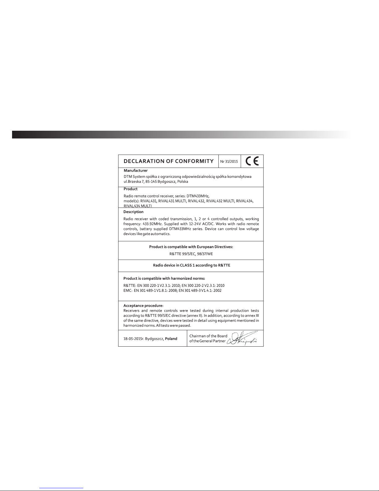
H. Certificates
All DTM System devices are certified according to European standards and are CE marked.
30
Page 34

I. Warranty
DTM System provides operational and ready to use devices. The producer gives 24 months warranty from the selling date to the end
customer. This time is counted according to the producer warranty labels or serial numbers placed on every product. Producer obliges himself to
repair the device for free if during the warranty period there are problems which come because of his fault. Broken device should be supplied on
customer's expense to the place of purchase and enclose clear and brief description of the breakage. The cost of mount/dismount is covered by
the user. The warranty does not cover: batteries in the remote controls, faults caused by improper usage, user self repairs and adaptations,
lightning strikes, voltages or short circuits in the electrical grid. Appropriate legal acts regulate details of the warranty.
J. Index
outdoor aerial - page 5
normally open (NO) - 3, 5
REMOTE:
Technical data - 29
Registering - 13, 18
Settings copying - 14
Buttons settings - 15
Remote number - 12
Simple registration - 9
Default settings - 15, 27
Deleting - 17
Registering - 9, 12
RECIEVER:
Simple registering blockade - 16, 23
PIN checking - 24
Turn on time - 19
Technical data - 29
Installation - 3, 4
Channels - programming - 19
Remote deleting - see: Remote-deleting
Memory cloning - 26
Number of remotes - 22
Double click - 21
Programming - 10
Default settings - 27
Momentary mode Remote registering - see: Remote-registering
PC communication (USB) - 28
31
Page 35

32
Number
001
002
003
004
005
006
007
008
009
010
011
012
013
014
015
016
017
018
019
020
Remote ID
Button no - 1 Button no - 2 Button no - 3 Button nr - 4
C-1 C-2 C-3 C-4 C-1 C-2 C-3 C-4 C-1 C-2 C-3 C-4 C-1 C-2 C-3 C-4
Tab. 2. Example of ID table for 20 remotes (table for 700 remotes can be downloaded at www.dtm.pl)
Page 36

MADE IN
POLAND
DTM System spó³ka z ograniczon¹ odpowiedzialnoœci¹
spó³ka komandytowa , ul. Brzeska 7, 85-145 Bydgoszcz
www.dtm.pl
 Loading...