

Page 1

phoyocell FOCUS / FOCUS FLASH
MOUNTING INSTRUCTION
1. Principleofoperation.
Photocell includestransmitter and receiver(fig.1).Thetransmitter emit acoded Irfrared
(IR) signal ,invisible to thenakedeye.Obstacle appearance (e.g. car)on photocell workingarea
produces a detection signal on receiver output. Receiver has NC and NO type output contacts.
Photocell is destined to work in gate automation system as external element. Built-in signal
lampsinboth,receiverandtransmitter,suppliedwith24V,fulfillsignalfunctioningatesystem.
2.Technical data.
•Guaranteed range 1-15m
•Powersupply oftransmitter and receiver 24VAC/DC
•Current consumptionof transmitter 2x25mA
• Powersupply ofsignal lamp 24VAC/DC
•Current consumtionof signalization lamp 2x40mA
•Workingtemperature (min./ max.) -20°C / +55°C
• dimensions(szer.x głęb.x wys.) 62x28x100mm
• Mounting surfacemounted,IP54
• Output contacts typuNOi NC
v.3.0
3. Photocellmounting.
For proper funcionality photocell must be mounted coaxial, 40-60 cm off the ground,
receiver and transmitter distance not less than 1 m . Because of photosensitive elements it is
recommended to mountreceiver onless sun exposure side.Both receiverand transmitter must
be mounted vertically. Terminal blocks and humidity carrying openings should be in the
bottom part of enclosure. Proper receiver and
transmitter adjustment is facilitated by
receiver's diode RX. RX diode lights when
transmitter ray reaches receiver. Both
enclosures should be mounted by 2 (diagonal
receiver - RX
LED signalling
LED signalling
RX
POWER
POWER
transmitter - TX
mounting) or 4 screws available in set. To scale
down photocell sensitivity (minor receiver and
Terminal blocks
transmitter distance) it is recommended to
dismounttransmitter'slens.
RX TXmax 15 m.
min 1 m.
Fig. 1 Receiver - transmitter location
DTM System spółka z ograniczoną odpowiedzialnością spółka komandytowa
ul. Brzeska 7, 85-145 Bydgoszcz, POLAND
tel./fax. (52) 340-15-83, 340-15-84
www.dtm.pl, dtm@dtm.pl
Page 2
phoyocell FOCUS / FOCUS FLASH
MOUNTING INSTRUCTION
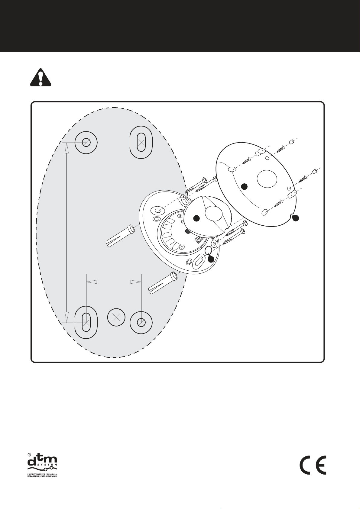
Do not mount mirrors or reflection screens in photocell's working area
Bewareofopticalreceiver/transmitterelementsstaining whilemounting.
1
3
2
72 mm
4
22 mm
Legend:
1. Cover
2. Humidity carrying opening
3. Splash proof internal bowl
4. Signal conduits opening =6mmf
USE THIS FIGURE
AS A TEMPLATE
Fig. 2 Assembly dimentions - scale 1:1, transmitter (receiver) assembly drawing
4. Photocellconnection
Photocell cooperates with most of gate controllers available on market. It is
recommended to do electrical installation and photocell mounting by qualified person.
Connect photocell according to fig. 3 scheme. First find 24V AC/DC clips (polarity is not
important!) intended to power supply, in gate controller. Connect power supply to receiver
and transmitter.When power is on red LED’s (POWER) in receiver and transmitter light. Next
connect gate controllerinput to photocell'sreceiver output (RX pins: 1,2or 2,3). Payattention
DTM System spółka z ograniczoną odpowiedzialnością spółka komandytowa
ul. Brzeska 7, 85-145 Bydgoszcz, POLAND
tel./fax. (52) 340-15-83, 340-15-84
www.dtm.pl, dtm@dtm.pl
Page 3

CONNECTION SCHEME
to controller's input type(NC orNO). Photocells usually workswith NCmode ingate automatic.
It is recommended to connect signal lamps parallely, supplied with 24V AC/DC, current
consumptionab.80mA.
5.Receivingtests
After photocell connection isdone, itis recommendedto checkreceiver(RX) reaction on
Inrfarared signal breaks. Gate automation systems must be tested conformity to EN 12445
standard. Photocell test: 1. Supply power to receiver only and check if RX diode out. 2. Supply
power totransmitter andchceck ifRX diodelight. 3. Displace roller of 5 cm diameter and 30 cm
length, to break perpendicularly optical axis between receiver and transmitter. First in the
vacinity of transmitter TX, next in the vacinity of receiver RX, next in the middle of distance
between them. In all cases photocell should switch from standby to alarm mode, which is
signalizedbyRXdiodewane.
transmitter - TXreceiver - RX
Gate controller
Peripherial supply OUTPUT
Signal lamp OUTPUT
24V AC/DC (min.80 mA)
- max. external diameter of conduits - 6mm,
- recommended twisted pair 4 x 2 x 0,5
in case of underground electrical installation use
gel-filled cable!
24V AC/DC
signal INPUT
photocell (NC)
COMMAND SIGNAL
POWER SUPPLY, polarity is not important
SIGNAL LAMP, polarity is not important
POWER SUPPLY
SIGNAL LAMP
1 2 3 4 5 6 7
LAMP
C NO
24V
AC/DC
24V
AC/DC
NC
transmitter - TXreceiver - RX
2 3 4
1
24V
LAMP
AC/DC
24V
AC/DC
Fig. 3. Photocell connection electric scheme
DTM System spółka z ograniczoną odpowiedzialnością spółka komandytowa
ul. Brzeska 7, 85-145 Bydgoszcz, POLAND
tel./fax. (52) 340-15-83, 340-15-84
www.dtm.pl, dtm@dtm.pl
Page 4

phoyocell FOCUS / FOCUS FLASH
MOUNTING INSTRUCTION
6.Warranty.
DTM System checks all the devices before shipping. The warranty time is 24 months
from the selling date. This time is counted according to the warranty label. The manufacturer
will fix all the problems which come because of his fault. Non functionaling device should be
delivered back to thedistributor withshortproblem description.The costof mount/dismountis
covered by user.The warrantydo not cover:batteries inthe remotes, faults causedby improper
usage, user self repairs and adaptations, lightning strikes, over voltages or short circuits in the
mainssupply.Appropriate legalacts regulates details of the warranty.
The intention of the WEEE Directive (Directive 2002/96/EC on waste electrical and electronic
equipment) is to reduce the amount of hazardous substances in waste.
The underlying purpose is to promote the avoidance, recovery and risk-free disposal of waste.
DTM System spółka z ograniczoną odpowiedzialnością spółka komandytowa
ul. Brzeska 7, 85-145 Bydgoszcz, POLAND
tel./fax. (52) 340-15-83, 340-15-84
www.dtm.pl, dtm@dtm.pl
 Loading...